How do I install a Honeywell GSMX4G on my VISTA system?
The Honeywell GSMX4G connects to the Vista panel's keypad bus. It comes with a handy keyed wiring harness. This means it can only be connected to the communicator with the correct orientation. At the opposite end are 4 separate wires. These connect to the Vista panel's keypad terminals.
The GSMX4G is an AT&T 4G cellular communicator with a small footprint. It can be used on any of the Honeywell Vista panels that support AlarmNet communicators in ECP mode. It does not come with an AC transformer, or back-up battery. Instead it draws all its power from the alarm panel to which it is connected. When transmitting, the GSMX4G draws 250 mA of current, and this must be taken into account when calculating Auxiliary Power current draw, and back-up battery requirements. To connect the GSMX4G to a Vista panel, follow these steps:
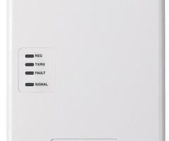
1. Determine a mounting location. The GSMX4G is often mounted right atop the alarm panel cabinet. Connect the wiring harness to the GSMX4G. Power the system completely down. Connect the black wire from the harness to panel terminal 4, and the red wire from the harness to panel terminal 5. Do not connect the yellow and green wires at this time. Power the system back up and wait for the signal LED to come on. When the signal LED is lit solid, this indicates a good, strong signal. Once you receive a solid signal LED, mark the location for mounting and power the system back down.

2. Mount the unit. If mounting atop the Vista panel's metal enclosure, remove the appropriate round knockout from the upper right side of the cabinet. At the lower right of the communicator, remove the plastic knockout. The box comes with a threaded mount used to attach the GSMX4G securely to the top of the panel's cabinet. It also comes with a metal washer to secure it in place.
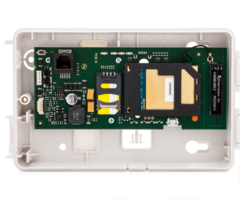
The picture below shows the GSMX4G with the plastic knockout removed, and the threaded mount, which is included with the GSMX4G. Insert the square head of the threaded mount into the grooves on the lower right of the communicator.

The picture below shows the threaded mount inserted, but not yet snapped into place.

The image below shows the threaded mount inserted and securely snapped into place.

Insert the prepared communicator's threaded mount into the hole created by removing the metal knockout from the panel's enclosure. Use the included metal washer to secure it in place.

If mounting the GSMX4G away from the panel, and the wiring will be fished through the wall, leave the plastic knockout at the lower right of the unit in place. The wiring will come through the wall and routed through one of the holes in the back of the unit. If you plan to surface mount the wiring, remove the plastic knockout and route wiring through the hole created.
Once you've selected a location where good signal strength is available mark the location for the two mounting screws. Drill pilot holes for the screws. Use drywall mounting anchors if necessary. The mounting holes at the top of the GSMX4G are keyhole style so leave the screws out about a quarter of an inch, until the GSMX4G is mounted, then tighten them down.
3. Wire the GSMX4G to the Vista panel. At this point, the system should still be powered completely down. If the communicator is mounted at the top of the cabinet, the wiring harness that comes with it is long enough to allow it to connect to the panel's keypad bus. When the communicator is mounted away from the panel, wire will need to be spliced into the four wire harness then connected to the keypad bus. If you need to power the GSMX4G from a source other than the panel's auxiliary power output (the terminals which power keypads and other devices) it is recommended to use an auxiliary power supply, such as the AD12612 which will require its own back-up battery and transformer. When an extra power supply is used, there must be a common ground between the DC negative terminal on the power supply, and the panel's auxiliary negative terminal (terminal 4 on the Vista-20P style panels, and terminal 7 on the Vista-128BPT style panels). Once the wires from the harness can reach the Vista panel, make the following connections:
Vista-20P and similar panels: This picture assumes power for the communicator will be coming from the alarm panel, and not a power supply. From the GSMX4G wiring harness, the yellow wire should connect to the panel terminal 7. The red wire should connect to the panel terminal 5. The black wire should connect to panel terminal 4, and the green wire should connect to panel terminal 6.

Vista-128BPT and similar panels: This picture assumes power for the communicator will come directly from the alarm panel, not from a power supply. From the GSMX4G wiring harness, connect the yellow wire to panel terminal 9. Connect the red wire to panel terminal 6. Connect the black wire to panel terminal 7. Connect the green wire to panel terminal 8.

Example of a power supply being used: This image shows a Vista P series panel. The only difference when a Vista-128BPT style panel is used is the common ground terminal number. Terminal 7 is used on these panels.

Once the GSMX4G has been connected, and is properly powered, consult your alarm dealer to get the device registered. They will need the MAC and the MAC CRC from the sticker on the unit. With this information, they can complete the setup.
Did you find this answer useful?
We offer alarm monitoring as low as $10 / month
Click Here to Learn MoreRelated Products
Related Categories
- Answered
- Answered By
- Julia Ross