Go!Bridge Install Guide
Related Products
Related Categories
Document Transcript
Copyright © 2014 Linear LLC 1
2GIG-BRDG1-900
GO!BRIDGE IP COMMUNICATOR
INSTALLATION INSTRUCTIONS
The Go!Bridge IP Communicator™ (2GIG‐BRDG1‐900) provides Internet
connectivity between the monitoring service’s Central Station and the
Go!Control® Panel, when the panel is used as a household burglar alarm
system.
It supports automatic firmware updates, provides interactive security
services, and increases supervision using signal‐forwarding to the Central
Station. For wireless communication with the Control Panel, the 900MHz
Transceiver Module (2GIG‐XCVR) must be installed in the panel. For
Internet access, the Go!Bridge must be connected to the local network
router using an Ethernet cable (not provided).
Contents
Verify that the package includes the following:
• 1—Go!Bridge IP Communicator
• 1—5VDC USB Mini‐B Power Supply
• 1—Stand
• 1—Plastic Power Supply Bracket (includes Self‐Adhesive Backing
and Zip Tie)
• 1—Wall Socket Screw for Power Supply Bracket
• 2—Phillips Head Screws and Wall Anchors (to mount unit on wall)
• 4—Self‐Adhesive Vinyl Bumpers for use on unit or stand
Requirements
Before you install, program, and test the Go!Bridge IP Communicator,
ensure the control panel being paired with the Go!Bridge IP
Communicator meets these requirements:
• Firmware Version 1.12 (or higher)
• 2GIG‐XCVR 900 MHz Transceiver
IMPORTANT: For compliance with UL 1023: Household Burglar‐
Alarm System Units, the Go!Bridge must be installed in the
same room as the Internet modem or router.
NOTE: To protect data sent via the local wireless network, it is
recommended that you install the Go!Bridge IP Communicator on
a local network where either WPA (Wi‐Fi Protected Access) or
WPA2 (Wi‐Fi Protected Access II) encryption is already enabled.
After installing, programming, and testing the Go!Bridge IP
Communicator, you will need to register a new customer with the third‐
party monitoring service. See Registration on page 3.
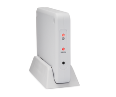
Figure 1 Go!Bridge Front View—LED Indicators and Learn Button
Powering ON the Go!Bridge IP Communicator
Use these steps to power ON the Go!Bridge IP Communicator:
1 Attach the power supply to the bracket (provided) as follows:
1a Insert the power supply into the enclosure on the plastic bracket.
See C in the figure below.
1b Secure the power supply to the retaining bracket by threading a
zip tie through the bracket’s slots. See D in the figure below.
1c Remove the strip from the self‐adhesive backing on the power
supply bracket.
1d Affix the adhesive on the bracket to the wall outlet. Then secure
the bracket to the outlet with the wall socket screw (provided).
NOTE: Always use the provided power supply bracket in the United
States (and other countries where it is required). Canada does not
require the power supply retaining bracket.
Figure 2 Power Supply and Bracket
2 Connect the Go!Bridge to the power source.
NOTE: Do not connect an Ethernet cable to the Go!Bridge IP
Communicator at this time. You will connect the cable when
completing the steps in Programming the Go!Bridge IP
Communicator into the Control Panel.
3 (Optional) Place the stand (provided) on a counter, desktop, or other
flat surface. Set the Go!Bridge IP Communicator in the stand.
NOTE: To protect surfaces from damage, affix the self‐adhesive vinyl
bumpers to the unit or stand.
4 Verify that the two (2) LEDs on the Go!Bridge IP Communicator
illuminate in RED. See Figure 1 Go!Bridge Front View—LED Indicators
and Learn Button on page 1.
A Network LED
B 900 MHz LED
C Learn Button
A 110V Wall Outlet
B Plastic Power Supply Bracket with Adhesive Backing
C AC Power Supply
D Zip Tie
2 Copyright © 2014 Linear LLC
Go!Bridge IP Communicator | Installation Instructions
NOTE: If the 900MHz LED illuminates in GREEN (the lower LED),
verify that the network cable is not connected to the Go!Bridge
IP Communicator. If the cable is disconnected and it is still
illuminated GREEN, use the end of an open paperclip to press
and release the recessed Reset button. The button is located
inside the small hole on the port side of the Go!Bridge IP
Communicator, directly above the Ethernet port. This restores
the factory settings. See Figure 3 Go!Bridge IP Communicator
Rear View—Ports and Recessed Reset Button.
Figure 3 Go!Bridge IP Communicator Rear View—Ports and
Recessed Reset Button
5 After the Go!Bridge IP Communicator is powered ON, continue with
Programming the Go!Bridge IP Communicator into the Control
Panel.
Programming the Go!Bridge IP Communicator
into the Control Panel
Use these steps to place the control panel and Go!Bridge IP
Communicator in learning mode. This gives the control panel the ability
to learn the network settings transmitted by the Go!Bridge IP
Communicator.
NOTE: To scroll between opons on the control panel, tap the ←
and → arrows. To move to the previous or next prompt tap the
↑ and ↓ arrows.
1 Connect an Ethernet cable (not included) to the router and
Go!Bridge IP Communicator. Do not plug the cable into the uplink
port.
IMPORTANT: For compliance with UL 1023: Household Burglar‐
Alarm System Units, the Go!Bridge must be installed in the
same room as the Internet modem or router.
2 Ensure the control panel is powered ON. Then tap the Home
button.
3 Tap the system logo in the lower‐right corner of the control panel
Home screen.
4 At the Enter Your Code screen, enter the four (4)‐digit master
installer code to go to the Installer Toolbox (1 of 2) screen.
5 At the Installer Toolbox (1 of 2) screen, tap System Configuration.
6 At the Q1: Select RF Sensor # (01 to 48) screen, tap Go To.
7 At the Enter Question Number (2 Digits) screen, enter 92.
8 At Q92 Select Network Device (0 to 1), tap → to scroll to (1)
Go!Bridge IP Communicator. Then tap ↓.
9 At Q: Network Device ID (Read Only), tap Learn. This gives the
panel the ability to discover the read‐only network device ID
transmitted by the Go!Bridge IP Communicator.
At the Pair with Xcvr Device screen, the “initiating learning
process” message appears.
10 On the Go!Bridge IP Communicator, press and release the Learn
button (this is the small, black plastic button on the LED side of the
Go!Bridge IP Communicator below the 900MHz LED). This transmits
the device ID to the Control Panel.
When the “learn operation succeeded” message appears and the
panel displays the Type (Go!Bridge IP Communicator) and ID#, the
Go!Bridge IP Communicator and panel are linked. The 900MHz LED
on the Go!Bridge IP Communicator also flashes GREEN.
11 At the Pair with Xcvr Device screen, tap OK. Then tap ↓ to
continue with Configuring the Go!Bridge IP Communicator Settings
below.
Configuring the Go!Bridge IP Communicator Settings
1 At the Q: Select Port # (1 to 8) screen, enter the port number for
the third‐party monitoring services’ server. Then tap ↓.
2 At Q: Used (0 to 1), tap → to select one (1) of these options:
• (0) Disabled (Recommended). This is the default setting. Most
users will keep this port disabled. Then tap Next and skip to
step 3.
OR
• (1) Enabled. Then tap ↓. At the Q: Enter Port Value (0‐65535)
screen, tap ↓ to accept the default port value. Next, at the Q:
Enter Port Forward IP Address screen, tap ↓ to accept the
address configured by the provider. You can configure up to
eight (8) ports. If you are finished configuring ports, tap Next.
3 At the Summary of Network Device screen, tap ↓. Verify the list of
port numbers and forward IP addresses appears as programmed.
Then tap Skip.
4 At Q93 Enter Broadband Network Failure Time (1 to 255), enter
the desired number of minutes that must pass before a network
failure triggers the Control Panel to issue a trouble alert. The
default value is 30 minutes. Then tap ↓.
NOTE: A trouble alert consists of an audible beep and the Control
Panel’s Home screen displays a trouble message.
5 At Q94 Select Broadband Network Failure Report (0 or 1), tap → to
select whether or not to report the broadband network failure to
the monitoring service:
• (1) Enabled. This is the default setting. Network failures are
reported to monitoring service.
OR
• (0) Disabled. Network failures are not reported.
6 Tap End.
7 At the Summary of System Configuration screen, verify the
settings. Then tap Save Changes.
8 Tap Exit to the close the System Configuration screen.
LED Indicators
The table details the LED indicators on the Go!Bridge IP Communicator.
A Recessed Reset Button
B Ethernet Port
C Power Supply Port
Network LED Globe Icon
Solid GREEN Indicates the presence of an external network connection.
Flashing GREEN Network cable is plugged in and IP address is actively being
assigned.
Solid RED Network cable unplugged.
900 MHz LED Icon Labeled “900MHz”
Solid GREEN Linked and communicating with the Control Panel.
Flashing GREEN Linked to the Control Panel. Communication issues exist.
Solid RED Not linked to the Control Panel, turns solid after a device
reset.
Flashing RED Not linked to the Control Panel.
Go!Bridge IP Communicator | Installation Instructions
Copyright © 2014 Linear LLC 3
Verifying the Settings
In addition to verifying the settings after configuring the Go!Bridge IP
Communicator, you can also verify the settings at any time as follows:
1 At the Control Panel’s Home screen, tap Security.
2 Tap Menu.
3 Tap Toolbox.
4 In the Enter Your Code to Access the Toolbox screen, enter the
master user code.
5 Tap → to scroll to the Toolbox (3 of 3) screen. Then tap Go!Bridge
IP Communicator Status.
A summary screen displays the following information:
• Network Configuration. The network type configuration.
• IP Address. The IP Address for the Go!Bridge IP Communicator.
This is a 32‐bit numeric address that identifies the device on the
network.
• Subnet Mask. The subnet mask for the network. All devices that
are joined to a network belong to a subnetwork.
• Gateway. The IP Address for the access point to the external
network. Typically, this is the IP Address of the local network
router or node that control traffic for your ISP.
• MAC Address. This is the Media Access Control (MAC) Address.
It is a physical address that is encoded to the Go!Bridge IP
Communicator during the manufacturing process.
Testing
The Go!Bridge IP Communicator tests the network connection to the
third‐party monitoring service. A report shows if Go!Bridge IP
Communicator has successfully connected (or failed to connect) to the
external server.
Registration
To register the Go!Bridge IP Communicator with the monitoring service,
refer to your specific provider’s registration instructions.
SPECIFICATIONS
Important Note
Should the local network lose Internet access due to a power outage or
interruption, the Go!Bridge IP Communicator is not equipped with a
backup battery system. To best prepare for power failures and to ensure
the security system maintains Internet access with the monitoring
service for life‐safety communications during power failures, the local
network must have a dedicated Uninterrupted Power Supply (UPS) or
backup battery solution from a third‐party manufacturer in place.
Linear LLC does not supply, provide, recommend, or test the Go!Bridge
with any UPS or battery backup solution. It is also assumed that owner’s
Internet Service Provider (ISP) maintains a backup battery (or power
generator) for their remote network equipment.
REGULATORY INFORMATION
Wireless Product Notice
Radio controls provide a reliable communications link and fill an
important need in portable wireless signaling; however, there are some
limitations which must be observed.
• For United States Installations Only: The radios are required to
comply with FCC Rules and Regulations as Part 15 devices. As
such, they have limited transmitter power and therefore limited
range (approximately 400 ft.).
• A receiver cannot respond to more than one (1) transmitted
signal at a time and may be blocked by radio signals that occur
on or near their operating frequencies, regardless of code
settings.
• Changes or modifications to the device may void FCC
compliance.
• Infrequently used radio links should be tested regularly to
protect against undetected interference or fault.
• A general knowledge of radio and its vagaries should be gained
prior to acting as a wholesale distributor or dealer, and these
facts should be communicated to the end users.
FCC Notice
This device complies with Part 15 of the FCC Rules. Operation is subject
to the following two conditions:
1 This device may not cause harmful interference, and
2 This device must accept any interference received, including
interference that may cause undesired operation.
This equipment has been tested and found to comply with the limits for
Class B Digital Device, pursuant to Part 15 of the FCC Rules. These limits
are designed to provide reasonable protection against harmful
interference in a residential installation. This equipment generates and
can radiate radio frequency energy and, if not installed and used in
accordance with the instructions, may cause harmful interference to
radio communications. However, there is no guarantee that
interference will not occur in a particular installation. If this equipment
does cause harmful interference to radio or television reception, which
can be determined by turning the equipment off and on, the user is
encouraged to try to correct the interference by one(1) or more of the
following measures.
• Reorient or relocate the receiving antenna
• Increase the separation between the equipment and receiver
• Connect the equipment into an outlet on a circuit different
from that to which the receiver is connected
• Consult the dealer or an experienced radio/TV technician for
help
Any changes or modifications not expressly approved by the party
responsible for compliance could void the user’s authority to operate
the equipment.
Wireless Signal Range 500 ft (152.4 m), open air, with Wireless Control Panel
Transceiver Silicon Labs SI1001‐E‐GM2
Transceiver Frequency 25 channel frequency‐hopping spread spectrum, 403
kHz channel spacing (910.2‐920.275 MHz)
Modulation Type GFSK modulation, 128 kpbs
RF Power +19dBm Maximum
Ethernet 10/100 BaseT
Dimensions (L x W x H) 6.24 x 4.5 x 1 in (159 x 114 x 25 cm)
Weight 9.6 oz
Housing Material Cycoloy™ Resin C2800 (Rated to UL 94 V‐0:
Flammability Standard)
Color White
Operating Temperature ‐32° F to 120° F, (0° C to +49° C)
Relative Humidity 5‐95% Non‐Condensing
Operating Voltage 5VDC
Certification ETL, FCC, IC, IFETEL, and NOM
4 Copyright © 2014 Linear LLC
Go!Bridge IP Communicator | Installation Instructions
Industry Canada (IC) Compliance
This device complies with Industry Canada license‐exempt RSS
standard(s). Operation is subject to the following two conditions: (1)
this device may not cause interference, and (2) this device must accept
any interference, including interference that may cause undesired
operation of the device.
Repairs to certified equipment should be made by an authorized
Canadian maintenance facility designated by the supplier. Any repairs or
alterations made by the user to this equipment, or equipment
malfunctions, may give the telecommunications company cause to
request the user to disconnect the equipment.
Users should ensure for their own protection that the electrical ground
connections of the power utility, telephone lines and internal metallic
water pipe system, if present, are connected together. This precaution
may be particularly important in rural areas.
WARNING: Users should not attempt to make such connections
themselves, but should contact the appropriate electric
inspection authority, or electrician, as appropriate.
LIMITED WARRANTY
This Linear product is warranted against defects in material and
workmanship for two (2) years. This warranty extends only to wholesale
customers who buy direct from Linear LLC or through Linear LLC’s
normal distribution channels. Linear LLC does not warrant this product
to consumers. Consumers should inquire from their selling dealer as to
the nature of the dealer’s warranty, if any.
There are no obligations or liabilities on the part of Linear LLC for
consequential damages arising out of or in connection with use or
performance of this product or other indirect damages with respect to
loss of property, revenue, or profit, or cost of removal, installation, or
reinstallation. All implied warranties for functionality, are valid only
until the warranty expires. This Linear LLC Warranty is in lieu of all other
warranties expressed or implied.
2GIG by Linear
1950 Camino Vida Roble, Suite 150
Carlsbad, CA 92008 USA
For technical support in the USA and Canada:
Dial: 855‐2GIG‐TECH (855‐244‐4832)
Email: 2gigtechsupport@linearcorp.com
Visit web site for technical support hours of operation
For technical support outside of the USA and Canada:
Contact your regional distributor
Visit dealer.2gig.com for a list of distributors in your region
77‐000044‐001 Rev. E
- Uploaded