Honeywell GSMX4G Quick Install Guide
Related Products
Related Categories
Document Transcript
GSMX4G / GSMXCN4G GSM Communicator – Quick Installation Guide
For Online Support visit: http://www.security.honeywell.com/hsc/resources/MyWebTech/
General Information
The GSMX4G GSM Communicator (GSMXCN4G in Canada) easily connects to your security system's control panel and sends alarms and messages to AlarmNet for subsequent transfer to the central monitoring station. The communicator can be mounted directly on the control panel or remotely. NOTE: This guide addresses a simple installation using default programming values where possible. For detailed information, refer to the GSMX4G / GSMXCN4G GSM Communicator Installation and Setup Guide. • The GSMX4G requires an AlarmNet account. For new installations, please obtain the account information from the central station prior to programming the communicator. • The GSMX4G is for control panels that support GSM communicators (or LRR, Long Range Radio) and the ECP communications bus. For control panels that do not support ECP, refer to the installation guide to use the 4204 mode. • The control panel treats the communicator as an ECP device, so ensure to program the control panel with the communicator’s device address. • The GSMX4G is for indoor use only. Standby current is 65mA, and Active Current is 380mA. REMOTE SERVICES Honeywell offers secure web based services that enable users to remotely monitor and control their security system. These web services enable users to: monitor and control their security system from a website, receive email and text message notifications of system events, and use text messages to control the system and receive confirmations. Dealers can enroll their customers for "Remote Services" by using the AlarmNet Direct website. Once enabled, the specific programming fields associated with these features can be programmed into the communications device either remotely using the AlarmNet Direct website or locally using the 7720P programming tool.
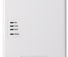
REG TX/RX FAULT SIGNAL
1. Mount and Wire the Communicator
SELECT A MOUNTING LOCATION When choosing a suitable mounting location, understand that it must be mounted indoors, and for best signal strength it should be mounted vertically. Signal strength is very important for proper operation. For most installations, mounting the unit on the control panel provides adequate signal strength and we suggest that this method is tried first (especially if the control panel is not in a basement location or in an area that contains large metal objects). If the control panel location does not provide adequate signal strength, then the communicator can be mounted remotely. NOTE: The SIM in the GSMX4G must be ACTIVATED first in order for signal strength to be determined. The SIM in the GSMXCN4G is already activated. ACTIVATE THE SIM Go to: https://services.alarmnet.com/AlarmNetDirect/ If you are not signed up for this service, click on “Dealer Signup” from the login screen to set up your dealer account. You will be instructed how to proceed upon completing the sign-up form. Only one sign-up per dealer is required. Once an initial user is established, additional logins may be created. Log in and follow the on-screen prompts. At this time only activate the SIM so signal strength may be checked. DO NOT register the communicator at this time. Please have the following information available to activate the SIM: • MAC ID and MAC CRC number (located on the box and inside the communicator). You may log out of the AlarmNet Direct website. VERIFY SATISFACTORY SIGNAL STRENGTH In this procedure you will temporarily power up the communicator to check for satisfactory signal strength. You can power it from a 12V battery or from the control panel's AUX PWR terminals. In buildings where reception may be a problem, powering from a battery would allow the communicator to be portable. The following procedure assumes the control panel will be used for power. 1. Ensure power to the control panel (both AC and battery) is off. Open the enclosure and connect the ECP cable to the communicator. Temporarily attach the Black and Red wires to the GND and AUX PWR terminals of the control panel. DO NOT connect the Yellow and Green wires at this time. 2. Turn power on and wait about one minute for the communicator to initialize. Position the communicator near a suitable mounting position. Verify the Minimum Signal Strength LED (green) is lit steadily. 3. Verify the signal strength remains steady for a few minutes, then mark that mounting position. Turn power off.
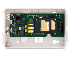
MOUNT THE COMMUNICATOR ON THE CONTROL PANEL 1. Ensure power to the control panel (both AC and battery) is off, then remove a knockout on the top right. 2. Open the cover and remove the bottom knockout for the threaded mount. Remove the Hole Cap attached to the plastic, and snap it into the top of the enclosure. 3. Install the threaded mount so it snaps into the plastic retaining tabs. Mount the communicator in the cabinet's knockout, and fasten with the locking nut. 4. Connect the ECP cable to the communicator’s circuit board and thread the wires through the threaded mounting adapter.
ECP Cable
Control Panel Cabinet
To ECP Bus on control panel circuit board.
PANEL DATA OUT - Yellow AUX PWR (+12V) - Red GND - Black PANEL DATA IN - Green
GSMLX-Quick Guide -02-V0
Threaded Mount
GSMX4G-Quick Guide-01-V0
Signal Strength ON = Satisfactory BLINKING = Marginal OFF = Unsatisfactory
NOTE: Although mounting the communicator on the control panel is preferred, it may also be wall mounted. When wall mounting, please follow these guidelines: • • • • • Use both mounting holes to fasten. Route the wiring through the communicator's rear or bottom wiring access hole. Ensure all wiring splices are located within the communicator’s enclosure. Secure all wiring with ties as necessary. Follow the recommended wire gauge sizes.
Minimum Wire Gauge #22 #20 #18 #16
Distance from Control Panel 75 ft (23m) 120 ft (37m) 170 ft (52m) 270 ft (82m)
2. Program and Register the Communicator
You can quickly program and register the communicator by using the AlarmNet Direct website, using the 7720P Programming Tool, or by phone. In addition, after you program the communicator, you can register it by using the Test Message / Registration switch. Using the AlarmNet Direct website to program and register: 1. Log in as you did to activate the SIM. 2. Refer to the online help file to program the new device. 3. Register the communicator. 4. DONE. Using the 7720P Programming Tool to program and register: 1. This procedure will program the GSMX4G for basic control panel communications. For advanced features and remote services refer to the product’s Installation and Setup guide. 2. Ensure the system is powered up and connect the programming tool to the communicator. 3. Accept all default settings except the following prompts which need to be answered. Then exit the programming mode.
PROMPTS 9 Device Mode (ECP)_ OPTIONS • ECP • 4204 Emu • Two 4204s DESCRIPTION Press the [space] key to scroll through the modes of operation. Choose the default ECP mode and press [ENTER]. NOTE: For other modes and advanced features, see the Installation and Setup guide.
4. The interactive registration feature allows the installer to register the communicator through a series of keyboard commands on the 7720P Programming Tool. This method of registration lets the installer monitor the registration process. Registering … Once the programming is complete, press the [Shift] plus the up arrow [↑] key on the 7720P. The registration message is sent and the unit waits for the acknowledgment. If this is a new installation and the city, central station, and customer numbers have been correctly entered, the GSMX4G is registered and this message is displayed. The communicator is now in full service and available for alarm reporting to the central station.
Registration SUCCESS
Using the Test Message / Registration switch to register: After programming, initiate the registration sequence by clicking the Test Message / Registration switch three times.
12
Primary City ID (??)_ Primary CS ID (??)_ Primary Sub ID (????)_
[01-99]
Enter the 2-digit primary city ID, 01-99 (decimal). Enter the 2-digit primary central station ID number, 01-FE (HEX). Enter the 4-digit subscriber account number, 0001-9999 (decimal).
13
[01-FE]
Using the Phone to program and register: You can program and register the communicator by calling the AlarmNet Support at 1-800-222-6525 (Option 1). (Monday–Friday 8:00 am to 9:00 pm, Saturday 9:00 am to 5:30 pm EST) You will need the following information: • MAC ID and CRC (located on the box and inside the communicator). • Subscriber information (provided by the central station), including a city code, CSID, and subscriber ID. • When Instructed to do so, triple click the TEST MESSAGE / REGISTRATION switch.
14
[0001-9999]
WARRANTY Go to: http://www.security.honeywell.com/hsc/resources/wa/ DOCUMENTATION AND ONLINE SUPPORT Go to: http://www.security.honeywell.com/hsc/resources/MyWebTech/ 2 Corporate Center Drive, Suite 100 P.O. Box 9040, Melville, NY 11747 Copyright ! 2012 Honeywell International Inc. www.honeywell.com/security
Ê800-10939bŠ
800-10939 1/12 Rev. B
GSMX4G-009-V0
NOTE: Account information is provided by the central station. Enter this information in prompts 12, 13 and 14.
TEST MESSAGE / REGISTRATION Switch
- Uploaded