Interlogix Simon XTi-5 - User Guide
Related Products
Related Categories
Document Transcript
Simon
®
XTi
-
5
User Manual
P/N
466
-
5257
• REV
A
•
16JUN
16
Copyright
©
2016
United Techno
logies
Corporation. Interlogix is part of UTC
Climate,
Controls & Security
, a unit of United Technologies Corporation. All rights reserved.
Trademarks and patents
The
Simon
®
XTi
-
5
name and logo are trademarks of U
TC
Fire
&
Security.
Other trade names used in this document may be trademarks or registered
trademarks of the manufacturers or vendors of the respective products.
Manufacturer
UTC Fire & Security Americas Corporation, Inc.
1275 Red Fox Rd., Arden Hills,
MN 55112
-
6943, USA
.
FCC compliance
This equipment has been tested and found to comply with the limits for a Class B
digital device, pursuant to Part 15 of the FCC Rules. These limits are designed to
provide reasonable protection against harmful interfer
ence in a residential
installation.
This equipment generates,uses and can radiate radio frequency energy and, if not
installed and used in accordance with the instructions, may cause harmful
interference to radio communications. However, there is no guara
ntee that
interference will not occur in a particular installation.
If this equipment does cause harmful interference to radio or television reception,
which can be determined by turning the equipment off and on, the user is
encouraged to try to correct t
he interference by one or more of the following
measures:
•
Reorient or relocate the receiving antenna.
•
Increase the separation between the equipment and receiver.
•
Connect the equipment into an outlet on a circuit different from that to which
the re
ceiver is connected.
•
Consult the dealer or an experienced radio/TV technician for help.
Changes or modifications not expressly approved by UTC Fire and Security could
void the user’s authority to operate the equipment.
This device complies with Industr
y Canada licence
-
exempt RSS standard(s).
Operation is subject to the following two conditions: (1) this device may not cause
interference,and (2) this device must accept any interference, including interference
that may cause undesired operation of the dev
ice.
Cet appareil est conforme avec Industrie Canada exempts de licence standard
RSS (s). Son fonctionnement est soumis aux deux conditions suivantes: (1) cet
appareil ne doit pas provoquer d'interférences et (2) cet appareil doit accepter toute
interféren
ce, y compris celles pouvant causer un mauvais fonctionnement de
l'appareil.
In accordance with FCC requirements of human exposure to radiofrequency fields,
the radiating element shall be installed such that a minimum separation distance of
20 cm is mainta
ined from the general population.
FCC: B4Z
-
910C
-
SIMON
IC: 1175C
-
910CSIMO
This Class B digital apparatus complies with Canadian ICES
-
3B.
Cet appareil numérique de la classe B est conforme à la norme NMB
-
003 du
Canada.
Contact information
www.utcfireandsecurity.com
or
www.interlogix.com
Customer support
www.interlogix.com/customer
-
support
IMPORTANT SAFETY
INFORMATION. READ ENCLOSED WARNINGS AND SAFETY INFORMATION.
THIS MANUAL CONTAINS PRODUCT SAFETY WARNINGS, WARRANTY DISCLAIMERS, LIMITATIONS OF
LIABILITY, AND OTHER TERMS AND CONDITIONS.
PRODUCT WARNINGS
THESE PRODUCTS ARE INTENDED FOR SALE TO, AND INS
TALLATION BY, AN EXPERIENCED SECURITY
PROFESSIONAL. INTERLOGIX CANNOT PROVIDE ANY ASSURANCE THAT ANY PERSON OR ENTITY BUYING ITS
PRODUCTS, INCLUDING ANY “AUTHORIZED DEALER”, IS PROPERLY TRAINED OR EXPERIENCED TO CORRECTLY
INSTALL SECURITY RELATED PRODUCTS.
A PROPERLY INSTALLED AND MAINTAINED ALARM/SECURITY SYSTEM MAY ONLY REDUCE THE RISK OF EVENTS
SUCH AS BREAK
-
INS, BURGLARY, ROBBERY OR FIRE; IT IS NOT INSURANCE OR A GUARANTEE THAT SUCH
EVENTS WILL NOT OCCUR, THAT ADEQUATE WARNING OR PROTECTION WILL BE PRO
VIDED, OR THAT THERE
WILL BE NO DEATH, PERSONAL INJURY, AND/OR PROPERTY DAMAGE AS A RESULT.
WHILE INTERLOGIX MAKES REASONABLE EFFORTS TO REDUCE THE PROBABILITY THAT A THIRD PARTY MAY
HACK, COMPROMISE OR CIRCUMVENT ITS SECURITY PRODUCTS OR RELATED SOFTWAR
E, ANY SECURITY
PRODUCT OR SOFTWARE MANUFACTURED, SOLD OR LICENSED BY INTERLOGIX, MAY STILL BE HACKED,
COMPROMISED AND/OR CIRCUMVENTED.
INTERLOGIX DOES NOT ENCRYPT COMMUNICATIONS BETWEEN ITS ALARM OR SECURITY PANELS AND THEIR
OUTPUTS/INPUTS INCLUDING, B
UT NOT LIMITED TO, SENSORS OR DETECTORS UNLESS REQUIRED BY
APPLICABLE LAW. AS A RESULT THESE COMMUNICATIONS MAY BE INTERCEPTED AND COULD BE USED TO
CIRCUMVENT YOUR ALARM/SECURITY SYSTEM.
BATTERY OPERATED SENSORS, DETECTORS, KEYFOBS, PANIC DEVICES AND OT
HER PANEL ACCESSORIES
HAVE A LIMITED BATTERY LIFE. WHILE THESE PRODUCTS ARE DESIGNED TO PROVIDE SOME WARNING OF
IMMINENT BATTERY DEPLETION THE ABILITY TO DELIVER SUCH WARNINGS IS LIMITED AND SUCH WARNINGS
MAY NOT BE PROVIDED IN ALL CIRCUMSTANCES. PERIODI
C TESTING OF THE SYSTEM IN ACCORANCE WITH
THE INSTRUCTIONS PROVIDED IN THE USER MANUAL IS THE ONLY WAY TO ENSURE ALL SENSORS,
DETECTORS, KEYFOBS, PANIC DEVICES AND OTHER PANEL ACCESSORIES ARE FUNCTIONING PROPERLY.
CERTAIN SENSORS, PANIC DEVICES AND OTHE
R PANEL ACCESSORIES MAY BE PROGRAMMED AS
“SUPERVISORY” INTO THE ALARM PANEL MEANING THAT THE ALARM PANEL WILL INDICATE A TROUBLE IN THE
EVENT IT DOES NOT RECEIVE A REGULAR SIGNAL FROM THE DEVICE WITHIN A CERTAIN PERIOD OF TIME (E.G.
12 HOURS). CERTAIN DEV
ICES CANNOT BE PROGRAMMED AS SUPERVISORY. DEVICES CAPABLE OF BEING
PROGRAMMED INTO AN ALARM PANEL AS SUPERVISORY MAY NOT BE PROPERLY PROGRAMMED RESULTING IN
A FAILURE TO REPORT TROUBLE WHICH COULD RESULT IN DEATH, SERIOUS INJURY OR PROPERTY DAMAGE.
WARRA
NTY DISCLAIMERS
INTERLOGIX HEREBY DISCLAIMS ALL WARRANTIES AND REPRESENTATIONS, WHETHER EXPRESS, IMPLIED,
STATUTORY OR OTHERWISE INCLUDING (BUT NOT LIMITED TO) ANY WARRANTIES OF MERCHANTABILITY OR
FITNESS FOR A PARTICULAR PURPOSE WITH RESPECT TO ITS SECU
RITY PRODUCTS AND RELATED SOFTWARE.
INTERLOGIX FURTHER DISCLAIMS ANY OTHER IMPLIED WARRANTY UNDER THE UNIFORM COMPUTER
INFORMATION TRANSACTIONS ACT OR SIMILAR LAW AS ENACTED BY ANY STATE.
(USA only) SOME STATES DO NOT ALLOW THE EXCLUSION OF IMPLIED WARR
ANTIES, SO THE ABOVE
EXCLUSION MAY NOT APPLY TO YOU. THIS WARRANTY GIVES YOU SPECIFIC LEGAL RIGHTS AND YOU MAY
ALSO HAVE OTHER LEGAL RIGHTS THAT VARY FROM STATE TO STATE.
INTERLOGIX MAKES NO REPRESENTATION, WARRANTY, COVENANT OR PROMISE THAT ITS SECURIT
Y
PRODUCTS AND/OR RELATED SOFTWARE (I) WILL NOT BE HACKED, COMPROMISED AND/OR CIRCUMVENTED; (II)
WILL PREVENT, OR PROVIDE ADEQUATE WARNING OR PROTECTION FROM, BREAK
-
INS, BURGLARY, ROBBERY,
FIRE; OR (III) WILL WORK PROPERLY IN ALL ENVIRONMENTS AND APPLICATI
ONS.
Simon XTi
-
5
User
Manual
i
Content
s
Introduction
................................
................................
..............................
1
Using the Simon XTi
-
5
security system
................................
.................
3
Panel controls
................................
................................
.......................
3
Main touch screen display
................................
..................
4
Simon XTi
-
5
features
................................
................................
............
6
Cross
-
zoning
................................
................................
......
6
Home security
................................
................................
.......................
7
Arming/disarming
................................
...............................
7
Arming e
rrors
................................
................................
......
7
Unvacated premises
................................
...........................
9
Swinger shutdown
................................
..............................
9
Exit/entry delay
................................
................................
....................
10
Silent exit
................................
................................
..........
10
No entry delay
................................
................................
..
10
Quick exit
................................
................................
..........
11
Exit delay extension
................................
..........................
11
Bypassing sensors
................................
................................
..............
11
Alarms
................................
................................
................................
12
Fire alarm verification
................................
.......................
12
Canceling and preventing accidental alarms
....................
12
Guidelines f
or preventing accidental alarms
.....................
13
Chimes
................................
................................
................................
13
Voice chime
................................
................................
......
13
Spec
ial chime
................................
................................
...
14
System status
................................
................................
......................
14
Using an offsite phone
................................
................................
........
14
Key fobs
................................
................................
..............................
15
Key fob
................................
................................
.............
15
How your system communicates
................................
..........................
17
Status beeps
................................
................................
.......................
17
Alarm sirens
................................
................................
........................
17
Trouble beeps
................................
................................
.....................
18
System configuration
................................
................................
.............
20
Settings menu
................................
................................
.....................
20
Code options
................................
................................
.......................
20
Menu navigation
................................
................................
..................
20
Event History
................................
................................
.......................
22
Direct Bypass
................................
................................
......................
22
Panel Status
................................
................................
........................
22
Chime
................................
................................
................................
..
23
ii
Simon XTi
-
5
User
Manua
l
Special chime
................................
................................
.....................
23
Voice Volume
................................
................................
.....................
23
Beep Volume
................................
................................
......................
23
Brightness
................................
................................
..........................
24
Default Screen
................................
................................
...................
24
Calibrati
on
................................
................................
..........................
24
Help
................................
................................
................................
...
25
Set time and date
................................
................................
...............
25
Emergency icon
................................
................................
.................
26
System tests
................................
................................
.......................
26
Programming
................................
................................
......................
27
Access codes
................................
................................
..
27
Security
................................
................................
...........
28
Phone numbers
................................
...............................
28
Sirens options
................................
................................
..
28
Version
................................
................................
...............................
29
Testing
................................
................................
................................
...
30
Sensor test
................................
................................
.........................
30
Sensor
testing notes
................................
........................
31
Comm test
................................
................................
..........................
31
Central station communication
................................
...........................
32
System download
................................
................................
...............
32
Reference information
................................
................................
..........
33
Alarm system limitations
................................
................................
.....
33
Emergency planning
................................
................................
..........
34
Your floor plan
................................
................................
.
35
Cleaning the touch screen
................................
................................
..
35
Disposal
................................
................................
.............................
36
Sensor and module locations
................................
.............................
36
Access codes
................................
................................
.....................
37
Delays
................................
................................
................................
37
Simon XTi
-
5
system quick reference
................................
..................
38
Simon XTi
-
5
User
Manua
l
1
Introduction
The
Simon XTi
-
5
uses wireless technology to warn your family about intrusion,
carbon mo
noxide and fire. The system communicates with a central monitoring
station and sends voice messages to an offsite phone.
The security system uses sensors that communicate alarms to the control panel
using radio waves. The system is supervised, meaning that
the panel checks the
status of each sensor to detect problems. If the panel detects trouble, it will notify
you with displayed and spoken messages, beeps, and indicator lights. A Simon
XT
i
-
5
installation may include any of the devices listed in
Table
1
below
.
Table
1
: Simon XT
i
-
5
system components
Component
Type
Description
Control
panel
Operates and programs your security system. It
communicates to you through disp
layed and spoken
messages. The panel can communicate to a central
monitoring station and send voice messages to your offsite
phone.
Touchpads
Simon XT talking
touch screen
and
Simon XT Talking
Touchpad
a
Controls the security system primarily from within
the house.
Key fob
a
This keychain touchpad controls the security system from
within or near the outside of your home.
Sensors
Indoor motion
Detects motion in protected indoor area. When motion is
detected, the panel may respond by sounding chimes or a
n
alarm.
Outdoor motion
Detects motion in a protected outdoor area. When motion is
detected, the system may respond by sounding chimes or
turning on outside lights. These sensors are not used for
intrusion detection.
Glassbreak
sensor
Glassbreak sensor
s respond to shock waves of breaking
glass.
Door/window
Detects the opening of a door or window.
Smoke
Detects smoke or a significant rise in temperature. They have
a built
-
in siren that sounds when smoke or a significant rise in
temperature is detecte
d.
Carbon monoxide
a
Detects carbon monoxide. They have a built
-
in siren that
sounds when carbon monoxide is detected.
a.
Not verified for use by UL.
You can send commands or instruct your security system through a series of key
presses on the panel, t
ouchpads, or a remote telephone.
2
Simon XTi
-
5
User
Manua
l
Table
2
: System communication devices
Device
Description
Control panel
You can enter commands for your security system using the graphical
user interface on the panel. Depending on how your system
is
programmed, you may need to enter an access code for certain
commands. An access code is a numeric code that allows
authorization to operate your security system.
Simon XT talking touch
screen
The two
-
way talking touch screen is a wireless device that
provides a
graphical user interface that allows you to: arm the system (doors,
windows, and motion sensors), disarm the system, activate a panic
alarm to call the central monitoring station in a
n
emergency, check
system status, and turn system controlled l
ights on or off, all while
providing voice feedback. The touch screen also provides trouble
beeps, entry/exit beeps and alarm sounds (
Panic, Police, or
Fire).
Key fob
Key fobs are handy for simple arming and disarming control functions.
They are portable
and can be carried offsite in a purse or pocket.
Telephone
Touchtone telephones can be used to communicate with your system
while you are offsite. Ask your installer if you have this feature.
Note:
The default master code is 1
-
2
-
3
-
4 when the security sys
tem is shipped
from the factory. You should change your code after your system is installed.
Simon XTi
-
5
User
Manua
l
3
Using the Simon XT
i
-
5
security system
You can operate the self
-
contained security system through several different
methods:
•
Use the main
screen
icons
to arm/disa
rm the system when you enter or exit
your home
, check system status,
and to determine which sensors are active.
•
Use the emergency screen to communicate with the central monitoring station
to report emergency
panic
, police, or fire alarms.
•
From the home
screen, press the Status & Settings
icon
to program
certain user features. (See
System configuration
on page 20
).
Note
:
Upon initial installation, the battery may not be fully charged for
as long
as 36 hours. A low battery icon will be present and trouble beeps will sound
until the battery is sufficiently charged. After the initial charge, should the
panel lose AC Power and experience a low battery condition, the icon will
appear and troub
le beeps will sound unless silenced. You can silence trouble
beeps by:
•
Arming or disarming the system.
or
•
Pressing the STATUS & SETTINGS icon and pressing LISTEN next to
Panel
Status.
This will disable the sounder for 4 hours but the trouble i
ndication will remain
until the battery is recharged.
Contact your installer to replace your backup battery.
This system is intended to be checked by a qualified technician at least once
every 3 years.
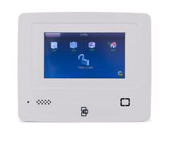
Panel controls
The self
-
contained panel provides the
user interface for system operation and
programming system functions.
4
Simon XTi
-
5
User
Manua
l
Figure
1
: Simon XT
i
-
5
controls
Note
: The touch screen in
Figure
1
above
is an example. You
r touch screen and
system may be configured differently.
Table
3
below
provides a description of the panel
’s
graphical user interface and
audio
.
Table
3
: Panel
featur
es
Control
Description
Piezo siren
Provides alarm beeps and status beeps.
Touch screen
Provides a graphical user interface for programming and system
operation.
Microphone
Used to communicate with the central monitoring station after an
alarm.
Speake
r
Provides voice output and sounds key beeps.
Main touch screen
display
While the panel is idle, the screen displays:
Table
4
:
Main
screen icons
Access the emergency screen to select the appropriate emergency
icon
(Panic, Police,
or Fire)
.
Time
The current system time
These icons only appear in red on the main screen if the backup
battery is
not fully charged or the AC power
is
not working correctly. It is
recommended that the
backup battery be replaced every 3
-
5 years.
Contac
t your installer to replace the backup battery.
Simon XTi
-
5
User
Manua
l
5
Depicts monitored door status. A green check indicates all monitored
doors are closed. A red exclamation point indicates one or more doors are
open.
N/A
indicates
your system is not configured to suppo
rt
door
sensor
s
.
Depicts monitored window status. A green check indicates all monitored
windows are closed. A red exclamation point indicates one or more
windows are open.
N/A indicates your system is not configured to support
window sensors.
Depicts motion detected by the motion sensors in your home. A green
check indicates no recent motion detected. A red exclamation point
indicates motion was detected within the last 10 minutes. A typical use for
this feature would be to have a
Simon two
-
wa
y talking
touch screen in the
garage to see if movement is detected in the home before you enter the
home.
N/A indicates your system is not configured to support motion
sensors.
Depicts other changes to protected property in your system. For example
activation of a water sensor, freeze sensor, or the movement of protected
items. A green check indicates no change since the last time you visited
(for movement of a protected item) and all sensors are closed (water or
freeze sensors). A red exclamation p
oint indicates either a sensor is
tripped or there is unacknowledged activity.
N/A indicates your system is
not configured to support property sensors.
Depending on the current arming state of your machine, one of these
icon
s will be displayed. Pr
ess the ARM
icon
to access the Arming Screen.
Press a DISARM
icon
, and provide a valid access code, to disarm your
system.
Note
: When disarming the system, on
ly intrusion/burglary sensors are
disarmed. Environmental sensors, such as smoke and carbon monoxi
de
detectors, stay active at all times
.
Note
: Depending on your configuration, the Motions Only icon may not
appear.
Press to access the settings screen.
This yellow triangle indicates faults within the system.
6
Simon XTi
-
5
User
Manua
l
Simon XTi
-
5
features
The Simon XTi
-
5
featur
es provide you with the ability to perform the following
functions:
•
Arm perimeter (doors and windows) and interior (motion) sensors to indicate
intruders.
•
Use the emergency screen to send quick response alerts to the central
monitoring station.
•
Access the system from a key fob (similar to the one used for your car).
•
Access the system from a remote telephone.
•
Disable sensors so you can leave a window open while the system is armed.
•
Get an audio alert when a protected door is opened while t
he system is
disarmed.
•
Get an audio alert if movement of a protected asset is detected (group 43).
Cross
-
zoning
Cross zoning (two
-
trip) refers to two different motion sensors that must be tripped
within two minutes of each other to report an alarm to the
central station.
Figure
2
below
shows the path of a person walking from the kitchen to the living room.
When the person is detected walking through the kitchen, the motion sensor in
the kit
chen is tripped, sounding a local alarm. If motion is detected by the living
room motion sensor within two minutes, an alarm report will be sent to the central
station.
Note
: Contact your installer for more information.
Figure
2
: C
ross
-
zone diagram
Simon XTi
-
5
User
Manua
l
7
Home security
The
Simon XTi
-
5
allows you to control which sensors are active at any given
time.
Table
5
below
describes the arming levels that you can set from the contro
l
panel.
Table
5
: Arming levels
Level
Function
Description
1
Disarm
In this level, only 24
-
hour sensors are active. Environmental
sensors (such as smoke or carbon monoxide detectors) stay
active at all times.
2
Arm door and
window
sensors
(
stay
)
This level arms the door and window sensors, while leaving the
interior motion sensors disarmed.
3
Arm motion sensors
(
away
)
This level arms the interior motion sensors, while leaving the
exterior door and window sensors disarmed.
Note
: De
pending on your configuration, this option may not
appear.
4
Arm doors/windows
and motion sensors
This level arms all sensors.
Arming/disarming
Arming a sensor makes it active and allows the panel to generate an alarm when
a door or window is opened or w
hen an unauthorized person enters a specific
area. Disarming makes the sensor inactive in the system. The current arming
level is shown on the
screen (see
Table
4
on page 4
)
and changes in a
rming
level are announced on the speaker.
Arming errors
If you select an arming option on the Arm screen, and there is an arming
problem, an arming error message
screen
will appear, indicating what the
problem is and how to correct it. For example, you mig
ht see a message that
indicates that you need to close the front door.
Correct the problem as indicated or press Bypass. You will see the arming
countdown message at the bottom of the screen. You can
press
C
ancel and
enter your code to stop the arming proc
ess.
8
Simon XTi
-
5
User
Manua
l
Figure
3
: Pre arm screen
To disarm (level 1):
1.
Press PRESS TO DISARM
.
2
.
Enter your code when the keypad screen appears.
The panel displays and speaks Disarmed
and the panel beeps once.
To arm doors and windows (level 2)
:
1
.
Ensure that all doors and windows are closed.
2.
Press
.
3.
Press
DOORS & WINDOWS ONLY (STAY) (see
Figure
3
above
)
.
4.
If a code is required, enter your code when th
e keypad screen appears.
The panel speaks Doors and Windows On and starts an exit delay, and
sounds exit beeps in groups of two until the exit delay expires.
To cancel
arming press CANCEL ARMING on the countdown screen.
Simon XTi
-
5
User
Manua
l
9
To arm motion sensors (level 3):
1
.
Press
.
2.
Press
MOTION SENSORS ONLY (AWAY) (see
Figure
3
on page 8
)
.
3.
I
f a code is required, enter your code when the keypad screen appears.
The panel speaks Motions On, starts an exit
delay, and sounds exit beeps in
groups of three until the exit delay expires.
Note
: Depending on your configuration, this option may not appear.
To arm doors, windows, and motion sensors (level 4):
1.
Press
.
2.
Press
ARM ALL (AWAY) (see
Figure
3
on page 8
)
.
3.
If a code is required, enter your code when the keypad screen appears.
The panel speaks Doors and Windows On, Motions On, starts an exit delay,
and sounds exit beeps in groups of fou
r until the exit delay expires.
Unvacated premises
Unvacated premises is a feature that d
etermines whether the system
automatically arms down to level 2 (doors and windows) if you arm the system to
level 4 (doors, windows, and motion sensors) without
openi
ng or closing a
perimeter door
(on), or remains at the armed level chosen (off). This feature does
not work from a key fob. Autobypass must be on for this feature to work.
Ask your installer how this option is programmed.
Swinger shutdown
This setting det
ermines if a sensor or zone will go into alarm only once during an
arming period (an active arming level) and will not be active again until the alarm
is canceled (
S
winger Shutdown is enabled) or the sensor or zone will always be
active and will go into al
arm multiple times during an arming period (an active
arming level) without canceling the alarm (Swinger Shutdown is disabled).
Note
: Swinger shutdown does not affect Smoke, Fire, Carbon Monoxide and
Environmental sensors.
Ask your installer how this opti
on is programmed and have them explain how it
will affect your system operation.
10
Simon XTi
-
5
User
Manua
l
Exit/entry delay
Your
Simon XTi
-
5
provides a delay after entering or exiting your home before the
system is armed
or disarmed
.
Table
6
below
provides details for the entry and
exit delay features.
Table
6
: Entry and exit delay details
Function
Description
Entry delay
Some active sensors cause immediate alarms when tripped. Other
sensors,
if enrolled in a delayed response group, start an entry
delay that lets you enter the premises and disarm the system. When
you enter your home, you will hear beeps during the entry delay
(see “
Status beeps
”
on pag
e 17
). If the system has not been
disarmed by the end of the entry delay, an alarm occurs.
The entry delay time is programmed by the installer.
No delay
If the system was armed with the no delay feature activated, there
will be no
entry delay and the alarm will occur immediately.
Exit delay
The exit delay is the amount of time the system gives you to exit the
home before the system is armed. During the delay, you can vacate
the premises through a delayed response door without causi
ng an
alarm.
Beeps will sound during the exit delay (see “
Status beeps
”
on
page 17
). The exit delay time is programmed by the installer.
Protest during arming
The system may protest an arm
ing level change if certain abnormal
conditions exist. If a sensor that is active in the requested arming
level is open, the system sounds protest beeps and automatically
bypasses the open sensor (depending on the system configuration).
Silent exit
The si
lent exit feature silences the status beeps that accompany the exit delay.
Press
ON next to
Silent
exit (
Figure
3
on page 8
)
before
pressing the arming
level icon
to silence status beeps. Th
e panel will still beep at the beginning and
end of the exit delay.
Note:
Enabling silent exit doubles the exit delay time.
No entry delay
Use the no entry delay feature when you are staying at home, or when you are
away from home and will
carry a wireless
keyfob
to disarm the system before
opening a protected door. Check with your installer to find out how this option is
programmed.
1
.
Close all door and windows.
2.
Press
.
3.
Press the O
FF
ne
xt
t
o
Entry Delay
(see
Figure
3
on page 8
).
Simon XTi
-
5
User
Manua
l
11
4.
Press your desired arming level
. The arming countdown begins
.
The screen displays
(clock with a red strike through)
with
your arming level
and speaks Doors and Windows On, No Entry Delay.
Note:
To avoid causing an alarm, you must disarm the system with a wireless
keyfob
before entering your home.
Quick exit
Use the quick exit feature when you want to briefly leave the house while the
system is stilled armed (for instance to get the newspap
er). This feature must be
enabled by your installer.
To enable Quick Exit
:
1
.
P
ress PRESS TO DISARM
.
2
.
P
ress
on the
touch
screen
.
This will start a 2 minute timer that will allow a designated exit door to be open
and
closed once without triggering an alarm.
Note:
The designated door may be opened and closed only once. If you close
the designated door behind you when you exit, you will need to disarm the
system upon re
-
entering. Leave the designated door open while usi
ng the quick
exit feature.
Exit delay extension
If enabled by your installer, the exit delay extension feature will recognize when
you arm the system, leave your house and then quickly re
-
enter (for example, if
you forget your car keys). If this happens, t
he system will restart your exit delay
to give you the full exit delay again.
Bypassing sensors
Bypassing a sensor allows you to open the sensor while the system is armed.
For example, if your doors and windows are armed and you want to open your
kitchen w
indow, but do not want to disarm the entire system, you can bypass the
kitchen window sensor and then open the kitchen window without causing an
alarm. Bypassed sensors are automatically unbypassed when the arming level is
changed to a level where the sens
or is not active.
To bypass, or
u
nbypass, a sensor:
1.
Press
.
2.
P
ress SELECT
.
3.
Enter your master code
.
12
Simon XTi
-
5
User
Manua
l
4.
Next to the sensor name, select
to bypass the selected sensor, or
to not bypass the selected sensor.
Alarms
The system provides a series of
alarms that indicate an unusual occurrence.
When an alarm is active, the
red alarm pop
-
up
display shows
with a message
explaining what caused the alarm
:
To
listen to and
cancel
an
alarm
:
1
.
If you would like to hear additional alarm i
nformation, press Listen.
2
.
To cancel the alarm, press the red alarm icon and enter a valid master or user
code.
After alarms are canceled, the system will be disarmed.
Fire alarm verification
If this option is off, the panel immediately
reports to the central station when a
smoke detector goes into alarm.
With this option on, if a single smoke detector goes into alarm, the panel will not
report for 60 seconds unless another smoke detector goes into alarm. If the first
smoke detector is cl
eared of
an
alarm within the first 60 seconds, no report will
be sent to the central station unless it or a second smoke detector goes into
alarm within the panel siren timeout period (5 minutes).
Ask your installer how this option is programmed.
Canceling
and preventing accidental alarms
One of the biggest concerns you might have regarding your security system is
causing an accidental alarm. Most accidental alarms occur when leaving the
residence after arming the system or before disarming the system upon
your
return.
There is a communicator delay (dialer delay) of 30 seconds programmed into the
panel. The panel will delay 30 seconds before dialing the central monitoring
station remote phone to send reports. You can have your installer program this
delay ti
me between 15 and 45 seconds. To cancel an accidental alarm before the
programmed dialer delay time expires, press the red alarm pop
-
up and enter
your access code. The panel will speak
Alarm C
ommunication C
ancel
led
Simon XTi
-
5
User
Manua
l
13
and sound beeps.
If the panel announces “
Alarm Cancelled”, the alarm report
was sent to the central monitoring station. (optional)
The central monitoring
station should be contacted to report the false alarm.
Note
: The
re
is no dialer delay for fire alarms.
Guidelines for preventing accidental ala
rms
Use the following guidelines to prevent accidental alarms:
•
Close doors and windows before you leave your house.
•
Gather your belongings, so you can exit immediately after arming the system.
•
Always enter and exit within the programmed delay times.
•
Make sure you leave through a door that has a delay time set for it.
•
Disarm your system immediately upon returning home.
•
Be aware of the devices in your system and learn how each one operates.
•
If you have pets, ask your installer if you need pet le
nses in your motion
detectors.
•
Check the location of your smoke detectors. Smoke detectors near
bathrooms and kitchens can be tripped by steam and smoke formed by
cooking.
•
Make a note of the display, system beeps, and indicator lights that indicate
the
current system status.
Chimes
Use the chime feature to signal when a protected door is opened while the
system is disarmed. The panel chimes twice when a chime sensor is tripped, if
the chime mode is enabled. This feature allows you to be notified when fa
mily
members are going in and out of your home. The chime and special chime
features are turned on or off in the System menu. See “
Chime
”
on page 23
and
“
Special chime
”
on page 23
.
Note:
If there are no chime sensors in your system, the chime option will not
appear in the System menu.
Voice chime
Your installer may have programmed the system to speak the sensor name or
make a c
ustom chime sound when a chime sensor is tripped. The chime sound,
if programmed, will be played in place of the standard chime beeps.
14
Simon XTi
-
5
User
Manua
l
Special chime
The special chime feature allows you to install motion sensors in a patio or at the
front door, and be noti
fied when someone is approaching those areas. These
motion sensors are not used for intrusion protection. The panel will chime three
times, if the special chime mode is enabled.
Note:
If there are no special chime sensors in your system, the special chime
option will not appear in the System menu.
System status
Press
and then press
next to Panel Status
(no code is required) to
cause the system to speak the following types of information:
•
Alarm conditions
•
Alarm history
•
Trouble conditions
•
Open sen
sors
•
Bypassed sensors
The
icon
and
icon
have a
when an abnormal condition such as a
trouble sensor exists in the system.
You can clear certain status entries from the system (such as old alarm history)
by listening to the message
and then
pressing
Clear next to Panel Status in the
Status & Settings screen.
Alarm history can
not be cleared when the system is
armed.
Using an offsite phone
(This feature has not been verified for use by UL.)
If enabled by the installer, you can control your Simon XT
i
-
5
s
ystem
remotely
from an offsite phone. The panel answers a phone call according to the dialing
method programmed by your installer.
After a certain combination of rings and pauses, the panel will answer the call
with the voice prompt Enter Your
Access
Code.
You must enter the correct code
to gain access.
If you are interacting with your panel and the panel hangs up on you, the system
is calling in a report to the central monitoring station or remote phone due to an
action by you or someone at the security sy
stem site. The actions listed in
Table
7
on page 15
may be performed from an offsite phone.
Simon XTi
-
5
User
Manua
l
15
Table
7
: Phone controls
Action
Phone key presses
Comments
Disarm
1
System
not already disarmed
Arm doors and windows
2
Press 2 again to activate the no
delay feature
Arm motion sensors
3
Arm doors, windows, and
motion sensors
2
3
Listen in to house
5
to listen in to the house
Once in listen in to house the
following optio
ns are available:
•
0 or 1 to speak
•
3 or 6 to listen
•
7
to extend call
When in this mode, the user
cannot re
-
enter the previous
menu. You must hang up and call
back in to the panel to perform
additional functions.
Check status
0
Hang up
9
K
ey fobs
Touchpads are used to control the security system from any location within or
near your home.
Key fob
If your installer programmed the key fob with no entry delay, and you arm the
system with the key fob, you must disarm your system before entering the hom
e
to avoid causing an alarm.
If your installer programmed your system for remote touchpad arming, you must
enter your home to start the entry delay before you can use your key fob to
disarm the system.
Caution:
To avoid causing false alarms, check with you
r installer on how your
touchpad/key fob options are programmed.
Panic alarms need to be silenced from the panel, a remote touchpad, or another
key fob. They cannot be silenced from the same key fob that activated the alarm.
For any key press on the key fo
b, hold the button until the indicator light blinks.
The key fob has the following buttons:
•
Lock (closed lock icon)
•
Unlock (open lock icon)
•
Star (star icon)
•
Light (light bulb icon)
Table
8
on page 16
describes how to use the key fob buttons.
16
Simon XTi
-
5
User
Manua
l
Table
8
: Key fob button operation
Task
Instructions
Arm doors and windows.
Press the Lock button once.
Arm doors, windows, and motion
sensors.
Press the Lock button twic
e.
Send a panic (intrusion, silent, or
emergency) alarm to the central
monitoring station.
Press the Lock and Unlock buttons simultaneously for 3
seconds.
(Check with your installer to find out how the key fob
panic buttons will operate.)
Disarm your se
curity system
.
Press the Unlock button once.
Simon XTi
-
5
User
Manua
l
17
How your system communicates
Your system communicates by using status beeps, alarm sirens, panel
screen
messages
, and trouble beeps.
Status beeps
The panel sounds status beeps to alert you to various system ev
ents and
conditions.
Note:
You may receive a different number of status beeps if you press the
icon
s
quickly.
Table
9
: Status beeps
Activity
Beep response
Doors+Windows
Exit delay and entry delay beeps sound two times every 5
secon
ds and two times per second during the last 10 seconds.
If silent exit is used, the exit delay beeps will only sound twice
when you arm and twice when the exit delay expires.
Motions
Exit delay and entry delay beeps sound three times every 5
seconds and t
hree times per second during the last 10 seconds.
If silent exit is used, the exit delay beeps will only sound three
times when you arm and three times when the exit delay
expires.
Doors+Windows and Motions
Exit delay and entry delay beeps sound four time
s every 5
seconds and four times per second during the last 10 seconds.
If silent exit is used, the exit delay beeps will only sound four
times when you arm and four times when the exit delay expires.
Disarm
One beep.
Chime
Two beeps.
Special chime
Thre
e beeps.
Trouble beeps
Six beeps every minute.
Press Listen next to Panel Status to
stop beeps for 4 hours.
No activity beeps
a
Twenty beeps every minute for 5 minutes (feature must be
programmed by the installer).
Property/asset management
beep
a
The p
anel sounds one beep when an asset group sensor is
activated.
a.
These features have not been verified for use by UL.
Alarm sirens
Exterior and interior sirens make three different alarm sounds on the premises,
each indicating a different type of alarm. S
irens are programmed by the installer
to time out and stop sounding after a specified time.
18
Simon XTi
-
5
User
Manua
l
Table
10
: Siren sounds
Function
Fire
Intrusion
Emergency
Interior and panel siren
Temporal 3
Steady
Fast on/off
Exterior siren
Temporal 3
Steady
Note
: Temporal 3 refers to a continuous pattern of three siren pulses, then off for 1.5 seconds,
three siren pulses, then off for 1.5 seconds.
Trouble beeps
Your security system is able to automatically test itself for:
•
Power failures
•
Low bat
teries
•
Sensor supervision
•
Communication trouble with the central monitoring station
When your system detects one of the problems above, six rapid beeps sound
every minute until the trouble condition is corrected. To stop the trouble beeps,
press
and
then press the
icon
or arm then disarm the system while the
trouble condition exists. Trouble beeps will resume 4 hours later unless the
trouble condition is corrected.
Table
12
describes the trouble beep conditions.
Table
11
: Trouble beep conditions
Condition
Description
AC power failure
This condition occurs if your security system has been
accidentally unplugged or if there has been an AC power outage.
The
icon
will appear in the top lef
t corner of the screen
display
, and trouble beeps start after 5 minutes. If AC power is not
restored within a programmed period of time (5 to 254 minutes
, if
programmed by the installer)
, the system will call the central
monitoring station. The backup batt
ery, if fully charged, will last for
18 to 24 hours (depending on the load applied to the panel) with
no AC power.
In a UL Installation, a new, fully charged battery will last 24 hours
with the panel in normal standby condition and still sound an
alarm.
System battery failure
This condition occurs if the emergency backup battery has failed.
Trouble beeps will start
and the
icon will appear in the top left
corner of the
main
screen.
If your AC power is not working, your
securit
y system will shut down once the battery has failed. If the
condition does not clear after AC power has been restored and
24
hours
have passed, call your security system dealer.
Simon XTi
-
5
User
Manua
l
19
Condition
Description
Restoration of power
This condition occurs after a complete loss of power (AC
and
battery). When power is restored, the panel will return to the
arming state with the same zones bypassed it had prior to losing
power.
Sensor failure
This condition occurs if a sensor is not communicating with the
panel. Trouble beeps will start
.
You
may need to call your security
system dealer if the problem continues.
Sensor low battery
This condition occurs if a system sensor has a low battery. The
sensor may still be communicating with the panel. Trouble beeps
will start
.
Press
and then
press
in the
STATUS &
SETTINGS
menu
.
T
he panel will speak which sensors have low
battery. You may need to call your security system dealer to
resolve this problem. Some sensor batteries can be replaced by
the homeowner.
Failure to communicate
This condition occurs if your security system
could not
communicate
successfully
to the central monitoring station. Your
system will try to report to the central monitoring station eight
times before it tells you there is a fail
-
to
-
communicate problem.
Tro
uble beeps will start and the yellow triangle appears over the
settings
icon
. You may need to call your security system dealer if
the problem continues.
Sensor open
This condition occurs if a door or window is open or a system
sensor has been disturbed a
nd not reset properly. For example, a
door/window sensor magnet may have been removed from the
sensor. Your system will indicate this condition to you by
displaying a red SENSOR OPEN icon
(see
Table
4
on page 4
)
and show the
icon
in the bottom right of the main screen
.
Correct the problem by resetting the sensor. If this condition
continues, call your security system dealer.
Sensor tampered
This condition occurs when a sensor is physi
cally tampered with,
for example, that the cover is taken off one of the sensors. If the
system is armed, an alarm will occur
and the red alarm pop
-
up
appears. If the system is disarmed, the
Sensor icons change to
red
(see
Table
4
on page 4
)
,
icon appears
,
and
Trouble
beeps will start. Correct the problem by resetting the sensor. If
this condition continues, call your security system dealer.
RF jam detected
The panel receiver may be experi
encing some interference. The
system will call to notify the central monitoring station about this
problem.
Clearing status
Some types of status conditions, such as alarm history, must be
cleared manually. To clear system status, press
CLEAR next to
Panel
Status
in the
STATUS & SETTINGS
menu. If the trouble
condition was a low system battery, perform a sensor test. The
should disappear if all trouble conditions have been corrected.
20
Simon XTi
-
5
User
Manua
l
System configuration
Your Simon XT
i
-
5
security system allows you to pro
gram certain user options.
These options are accessed through the settings menu.
Settings menu
To enter the settings menu, press
located at the bottom right of the main
screen.
Press
to exit a menu or option edit mode and navigate up one level.
The pan
el automatically returns to the main screen after one minute of inactivity
(4 minutes while performing a sensor test
,
5 seconds while entering an access
code).
Code options
The Simon XT
i
-
5
security system provides a system of codes to be entered when
a cer
tain level of authority is required to perform an action. These codes allow
you to activate system options, customize panel operations, and generate a
silent alarm. The default code is based on the code length (3, 4, 5, or 6
-
digit
code) determined at insta
llation. The code types are listed in
Table
12
below
.
Table
12
: Code types
Code
Description
Master code
The master code is the main code used for panel operations. T
he
default code will be 123, 1234, 12345, or 123456 depending on the
value set by the installer for code length.
User codes 1 through 8
These eight codes are supplemental user codes. You can use these
codes for panel operations such as disarming, but not
programming.
These codes can be any 3, 4, 5, or 6
-
digits, depending on the code
length.
Duress code
Use the duress code to generate a silent duress alarm while disarming.
Note:
Any combination of invalid codes in excess of 40 key presses (such as
fourtee
n invalid three
-
digit codes) will cause a system access alarm. The alarm
locks all touchpads, except key fobs, for 90 seconds.
Menu navigation
Each menu contains a list of options and/or submenus. Changing screens and
navigating menus is accomplished by us
ing the various on
-
screen interactive
icon
s. When accessing
menus such as
Programming or System Tests, the panel
Simon XTi
-
5
User
Manua
l
21
prompts you to enter an access code. To continue, enter your master code
on
the keypad
and then press OK.
A gold icon
indicates an option is s
elected
.
A blue icon depicts
indicates an option is not selected
.
To program an option, first navigate to that option until it is displayed
using the
icons
and then press the corresponding interactive
icon
(e.g. checkbox,
radio
icon
, data entry window
etc.
)
If pressing the option value’s interactive
icon
transitions to another screen,
make your changes there and press save or cancel
when done.
Press
to enter the
STATU
S
& SETTINGS
menu
.
Table
13
: Settings Menu structure
Event Hi
story
Direct Bypass
Panel Status
Chime
Optional. Ask your dealer for more information.
Note
: Has not been investigated by UL.
Special Chime
Optional. Ask your dealer for more information.
Note
: Has not been investigated by UL.
Lights
Optio
nal. Ask your dealer for more information.
Note
: Has not been investigated by UL.
Door Locks
Optional. Ask your dealer for more information.
Note
: Has not been investigated by UL.
Voice Volume
Beep Volume
Brightness
Default Screen
Calib
ration
Help
Set Date/Time
System Tests
Sensor Test
Comm Test
System Download
Programming
Access Codes
Master Code
User Codes 1 to 8
22
Simon XTi
-
5
User
Manua
l
Duress Code
Security
Downloader
Enable
Phone Numbers
Phone Number 4
Siren Options
Panel Piezo
Beeps
Panel Voice
Panel Piezo
Alarms
System Tests
Sensor Test
Comm Test
System Download
Interactive Services
Note
: Optional. Ask your dealer for more
information. Has not been investigated by
UL.
Version
Event History
The panel will k
eep a history of the most recent 40 events. Press Show
,
next to
Event History
,
to see them listed chronologically with the newest event at the top
of the list.
Note
: If a # appears in the Event History list, the event was not sent to the central
station.
Direct Bypass
The panel will allow learned in sensors
that are actively armed
to be bypassed,
so that they will not cause an alarm when the panel is armed. Press Select
,
next
to Direct Bypass
,
and provide a valid access code to access this menu.
The list
s
hows all of your sensors with their current state (bypassed or not bypassed),
press the state to change it.
Panel Status
Press the
Listen
,
next to Panel
Status
,
to
have the panel speak the current status
of the panel.
If the
icon appears a trouble condit
ion has occurred.
Press
Clear
to clear
certain
panel status messages.
Simon XTi
-
5
User
Manua
l
23
Chime
To enable or disable the chime feature:
1.
Enter the
Status &
Settings menu
and scroll to the Chime option.
2.
Press On or Off to modify the setting (
a gold icon indicates the opti
on is
selected
).
3.
Press Close to exit the Status & Settings menu.
Note:
This menu option will not appear if chime sensors are not in your system.
Special chime
To enable or disable the special chime feature:
1.
Enter the Status & Settings menu and scrol
l to the Special Chime option.
2.
Press On or Off to modify the setting (
a
gold
icon indicates
the
option is
selected
).
3.
Press Close to exit the Status & Settings menu.
Note:
This menu option will not appear if special chime sensors are not in your
syste
m.
Voice Volume
The Voice Volume will control volume of the voice and key beeps (the volume
when keys and buttons are pressed)
From the Status & Settings screen, next to Voice Volume, press the left arrow to
lower the voice volume and the right arrow to r
aise the voice volume. The bars
between the arrows register the volume level.
No
bar
s
is
off
. Four bars is loudest.
Beep Volume
Beep volume will control the volume made for status beeps, trouble beeps and
exit / entry beeps.
From the Status & Settings s
creen, next to Beep Volume, press the left arrow to
lower the beep volume and the right arrow to raise the beep volume. The bars
between the arrows register the volume level. One bar is softest. Four bars is
loudest
24
Simon XTi
-
5
User
Manua
l
.
Brightness
From the Status & Setting
s screen, next to Brightness, press the left arrow to
make the screen less bright and the right arrow to make the screen more bright.
The bars between the arrows register the brightness level. One bar is least
bright. Four bars is brightest.
Default Scre
en
From the Status & Settings screen, press MAIN or BLANK next to Default
Screen. To make options visible on a blank screen, touch anywhere on the
screen. The screen will stay visible for two minutes before returning to blank
mode, if untouched.
The green
AC power icon will blink when in BLANK mode.
Note:
The touch screen will automatically blank at 2:00 am daily for
60
minutes.
Touch the screen to reactivate.
Calibration
The touch
screen should arrive with proper screen calibration. This feature
should o
nly be used if there is a problem with your touch
screen’s calibration.
To calibrate the screen:
1
.
From the Status & Settings screen, press SHOW next to Calibration.
2.
Touch the center of the cross
using a soft, fine point
as it appea
rs in each
corner of the screen.
Simon XTi
-
5
User
Manua
l
25
After the cross in the fourth corner (bottom right) is pressed, the user will be
returned to the Status & Settings screen.
Help
Press the Help
icon
to access a menu showing how to perform basic tasks on
your
Simon XTi
-
5
.
1
.
From the Status & Setting screen, press the HELP
icon
.
2.
From the SYSTEM HELP screen, choose the help topic to search.
3.
Press
and
to scroll through help topics.
4.
Press CLOSE to return to the previous screen.
Set
time
and d
ate
If the panel loses both AC and battery power, upon power restoral the system
time will reset to midnight and the date will reset to 1
-
1
-
2000, indicating it has
not been set correctly.
Time format is: hour/minute/a.m. or p.m.
Date format is: month/
day/year:
To set the time
1
.
From the Status & Settings screen, select Set Date/Time.
2
.
Enter
master
access code.
26
Simon XTi
-
5
User
Manua
l
3
.
From the Set Date/Time screen press the first box to set hour and press
SAVE.
4
.
Press the second box to set minutes
and press
SAVE.
5
.
Press
a.m.
/p.m. box to toggle
a.m.
/p.m. setting.
To set the date
1
.
From the Set Date/Time screen press the
first box in the second row to set
month
and pre
ss
SAVE.
2
.
Pre
ss the second box to set day
and press
SAVE.
3
.
Press the third box and enter the year and press SAVE.
4
.
Press CLOSE repeatedly to exit.
Emergency
icon
In an emergency, touch the Emergency ic
on. An Emergency
screen appears
(See Emergency icon in
Table
4
on page 4
). Y
ou
will
see
three
icon
s (Panic,
Police, or Fire). Select the appropriate
icon
.
Note
:
If your system is connected
to a security monitoring service, the authorities
will be notified.
This option may not be enabled.
Contact your dealer for details.
If you initiate an emergency alarm by mistake, you can cancel the alarm by
touching the red
a
larm
icon
(“
Alarms
”
on page 12
)
and entering your code within
30 seconds (typical time limit, contact your dealer for more information on your
system configuration).
System tests
This menu lets you run sensor and commun
ication tests, and initiate a phone call
from the panel to Enterprise Downloader. For more information, see “
Testing
”
on
page 30
.
Simon XTi
-
5
User
Manua
l
27
Programming
To enter programming mode:
Note
: Programming mod
e can only be entered if the system is disarmed.
1
.
Enter the
Status &
Settings menu.
2
.
Scroll until
P
rogramming is listed, press the Enter
icon
.
3
.
Enter your master code, and then press OK.
Note
: You hav
e four seconds between number presses to enter the code or
you will be returned to the home screen.
At this point, you are in the Programming menu. At this level, the following
submenus are accessible:
•
Access
C
odes
•
Security
•
Phone
Numbers
•
Siren
O
pti
ons
•
System
T
ests
•
Interactive Services
(Optional. Ask your dealer for more information.)
The sections below describe the options that you can program in each of the
programming submenus.
Access codes
There are three types of access codes:
Master code.
The master code is your most powerful code and can be used for
all user operations including programming. The initial value of the master code is
123, 1234, 12345, or 123456, depending on the installer
-
programmed access
code length.
User codes 1 to 8.
Ther
e are eight user codes, which can be used for many
user operations, but not programming or bypassing sensors. Initially, all user
codes are blank. A user code can be deleted by pressing Delete while the code
is being changed.
Duress code.
The duress code,
when used in place of another user code,
generates a silent duress alarm that is reported to the central monitoring station.
Initially, the duress code is blank. The duress code can be deleted by pressing
Delete while the code is being changed.
To add/edit
access codes:
1
.
From the Programming screen, press ACCESS CODES.
2
.
To add or edit an access code, press the white field next to the access code.
3.
Enter the new/edited code on the numbered keypad and press SAVE.
28
Simon XTi
-
5
User
Manua
l
4.
Pre
ss CLOSE repeatedly to exit menus
.
Security
The Security menu contains the Downloader Enable option. This option
determines whether your dealer can access the system remotely.
To program the download enable option:
1
.
From the
Programming
screen, press SECURITY
.
2
.
Press the Security
icon
.
3
.
To turn on an option, press
. To turn off an option, press
.
Note
:
indicates the
option
is
turned on.
4.
Press CLOSE repeatedly to exit menus.
Phone numbers
Phone
n
umber
4 is the only system phone number that you can change.
Therefore, it is often used for voice reporting alarms to your phone and can be
programmed for this purpose by the installer.
Note
: Certain system options must be programmed by the installer for
voice
reporting alarms to work properly.
To add/edit phone number 4:
1
.
From the Programming screen, press PHONE NUMBERS.
2
.
To add or edit a phone number, press the white field next to the Phone
Number 4.
3.
Enter the new
/edited phone number on the numbered keypad and press
SAVE. To delete a phone number, press DELETE.
4.
Press CLOSE repeatedly to exit menus.
Sirens options
The panel has two built
-
in sound sources, a piezo siren and a speaker. The piezo
siren makes alarm b
eeps and status beeps.
Fire and intrusion alarm beeps are
always played at high volume, while the volume of status beeps (such as trouble
or chime beeps, entry and exit delay beeps, or
emergency
alarm beeps) is
controlled by the Beep Volume in the Status a
nd Settings screen
.
The speaker
emits the panel’s voice and sounds beeps when a key is pressed.
The siren
volume is also programmable.
The siren and built
-
in speaker options consist of the following:
Panel piezo beeps.
(
Status beeps sounded on the siren.)
This option
determines whether the panel sounds nonalarm beeps. To program piezo beeps:
Simon XTi
-
5
User
Manua
l
29
1
.
From the Programming screen, press SIREN OPTIONS.
2
.
To turn on panel piezo beeps, press
. To turn off, press
.
Note
:
indicates
the
panel piezo beeps are turned on.
3.
Press CLOSE repeatedly to exit menus.
Panel voice.
(Spoken phrases on the speaker and key press sounds from the
speaker heard while controlling the system.) This option determines whether the
panel speaks status mes
sages and arming level changes. To program panel
voice:
1
.
From the Programming screen, press SIREN OPTIONS.
2
.
To turn on panel voice, press
. To turn off, press
.
Note
:
indicates the
panel voice is turned on.
3.
Pres
s CLOSE repeatedly to exit menus.
Panel piezo alarms.
(Loud alarms on the siren). This option determines whether
the panel sounds alarm beeps. To program panel piezo alarm:
1
.
From the Programming screen, press SIREN OPTIONS.
2
.
To turn on panel piezo alarms, press
. To turn off, press
.
Note
:
indicates the
panel piezo alarms is turned on.
3.
Press CLOSE repeatedly to exit menus.
Caution:
T
urning this option off will disable all system sirens. This option should
only be
turned off if the panel is configured with external sirens. Ask your installer
for more information.
Version
This menu is a read
-
only display of the system’s firmware version, the touch
screen version, and copyright information.
30
Simon XTi
-
5
User
Manua
l
Testing
This section inclu
des:
•
Sensor t
est
•
Comm test
•
System download
Sensor test
You
should
test sensors one at a time to make sure they are sending strong
signals to the panel. You should test the sensors at least once a week.
To perform the sensor test:
1.
Enter the
Status
& S
ettings menu
.
2.
Scroll until System Tests is listed, Press Enter
.
3.
Enter your master code
and press OK
.
4.
Press Sensor Test
.
5.
All sensors learned into your system will be listed
.
6.
Test any sensor you want by tripping the sensor (see
Table
14
below
for
details on how to trip each device)
.
7.
The display will update with the total number of packets received from each
individual sensor
(see
Table
14
below
for minimum number of packets
required).
Table
14
: Tripping sensors for sensor test
Sensor
Instructions
Minimum
packets
required
Hardwire contact
Open the hardwire contact
1
Door/window
Open th
e secured door or window.
6 of 8
Carbon monoxide
alarm
a
Press and hold the Test/Hush
button
(approximately 5
seconds) until the unit beeps two times, and then release
the
button
.
6 of 8
Glassbreak
a
Test with an appropriate glass break sensor tester.
6
of 8
Motion sensor
Avoid the motion sensor field of view for 5 minutes, and
then enter its view.
6 of 8
Smoke
Press and hold the test
button
until the system sounds
transmission beeps.
6 of 8
Simon XTi
-
5
User
Manua
l
31
Sensor
Instructions
Minimum
packets
required
Key fob
Press and hold the Lock and Unlock
button
s
simultane
ously for 3 seconds.
6 of 8
Simon XT talking
touch screen
a
For sensor testing a 1.0. touch screen, press and hold
the Emergency
icon
for 5 seconds.
For sensor testing a 1.1 or greater touch screen, press
the Settings (gear)
icon
, scroll down, and then p
ress the
RF Test
icon
.
6 of 8
a.
Not investigated for use by UL.
Note:
Refer to specific sensor installation instructions for complete operation and
testing details.
Sensor testing notes
•
Conduct sensor test in all possible environmental conditions (
f
or
example:
interior doors open and closed, HVAC system on and off, wireless music
system
turned on and off)
.
•
Conduct sensor test whenever changes are made to the installation
environment
that may impact RF performance (
f
or example: mirrors installed,
metal
backed
wall paper, addition of other RF equipment)
.
•
If a sensor doesn’t meet minimum packet requirements, contact your installer.
Comm test
The comm test is used to check proper communication.
Note
:
I
f
C
omm Test is not finished
,
it will continue to run
even if you exit program
mode.
To perform a comm test:
1.
Enter the Status & Settings menu
.
2.
Scroll until System Tests is listed, Press Enter
.
3.
Enter your master code
and press OK
.
4.
Press Comm Test.
The panel displays if the comm test was
successful
or not.
32
Simon XTi
-
5
User
Manua
l
Central station communication
After performing sensor tests, check that the system is reporting alarms
successfully to the central station.
To test communication with the central station:
1
.
Call the central station and tell the
operator that you will be testing the
system.
2
.
Arm the system.
3
.
Test an emergency panic
icon
and trip at least one sensor of each type (fire,
intrusion, etc.) to verify that the appropriate alarms are working correctly.
There
could be
a 30 second delay
on intrusion devices
.
4
.
When you finish testing the system, call the central station to verify that the
alarms were received.
Note:
If your system is not connected to a central monitoring station you won’t
be
able to perform the communication test.
System download
You can initiate a download call to program your system with the settings
specified by your installer. Use this feature only when instructed by your installer
or dealer.
To initiate a download:
1.
Enter the
Status & S
ettings menu
.
2.
Scroll until System Tests is listed, Press Enter
.
3.
Enter your master code
and press OK
.
4.
Press the System Download
icon
.
Simon XTi
-
5
User
Manua
l
33
Reference information
This section provides information on system limitations, emergency pla
nning and
smoke and heat detector locations. It also provides a place to list your sensor
and module locations and other programming values.
Alarm system limitations
Not even the most advanced alarm system can guarantee protection against
burglary, fire, o
r environmental problems. All alarm systems are subject to
possible compromise or failure
-
to
-
warn for a variety of reasons.
•
If sirens are not placed within hearing range of persons sleeping in remote
parts of the premises, or if they are placed behind do
ors or other obstacles.
•
If intruders gain access through unprotected points of entry or areas where
sensors have been bypassed.
•
If intruders have the technical means of bypassing, jamming, or disconnecting
all or part of the system.
•
If power to senso
rs is inadequate or disconnected.
•
If freeze or any environmental sensors are not located in areas where the
appropriate condition can be detected.
•
If smoke does not reach a smoke sensor. For example, smoke sensors
cannot detect smoke in chimneys, walls
, roofs, or areas blocked by a closed
door. Sensors may not detect smoke in other levels of the building. Sensors
may not warn in time when fires are caused by smoking in bed, explosions,
improper storage of flammables, overloaded electrical circuits, or o
ther
hazardous conditions.
•
If telephone lines are out of service.
Inadequate maintenance is the most common cause of alarm failure. Therefore,
test your system at least once per week to be sure sensors, sirens, and phone
communication are all working cor
rectly.
Although having an alarm system may make you eligible for reduced insurance
premiums, the system is no substitute for insurance.
WARNING:
Security system devices cannot compensate you for the loss of life
or property.
34
Simon XTi
-
5
User
Manua
l
Emergency planning
Since an em
ergency is always unexpected, you should develop plans to help
prepare for a variety of emergencies. Periodically discuss and rehearse
emergency plans to include the following:
•
Understand how to use your security system.
•
Know the normal state of doors
and windows: open, closed, or locked.
•
Escape fast! (Do not stop to pack)
.
•
Use a different escape route if closed doors feel hot to the touch.
•
Crawl and hold your breath as much as possible to help reduce smoke
inhalation during your escape.
•
Meet at
a designated outdoor location.
•
Emphasize that no one should return to the premises if there is a fire.
•
Notify the fire department from a neighbor’s phone.
•
Emphasize that no one should enter the premises if they hear sirens in the
house.
•
If you arr
ive at the premises and hear sirens, do no enter. Call for emergency
assistance with your cell phone, or from a neighbor’s phone.
Simon XTi
-
5
User
Manua
l
35
Smoke Detector Placement
Your floor plan
Use the following guidelines when drawing your floor plan:
•
Show all building leve
ls.
•
Show exits from each room (two per room are recommended).
•
Show the location of all security system components.
•
Show the location of any fire extinguishers.
Cleaning the touch screen
If necessary, use a soft
lint
-
free
cloth to clear smudges on the
touch screen; do
not use glass cleaner on the touch screen.
36
Simon XTi
-
5
User
Manua
l
Disposal
Dispose of all equipment
in
accordance with local requirements.
Contact your installer for more information.
Sensor and module locations
Use
Table
15
below
to list your sensor and module locations.
Table
15
: Sensor and module locations
Sensor number
Sensor name
Sensor type
Location
Example
Front door
Door/window sensor
Front door
1.
2.
3.
4.
5.
6.
7.
8.
9.
10.
11.
12.
13.
14.
15.
16.
17.
18.
19.
20.
21.
22.
23.
24.
25.
Simon XTi
-
5
User
Manua
l
37
Sensor number
Sensor name
Sensor type
Location
26.
27.
28.
29.
30.
31.
32.
33.
34.
35.
36.
37.
38.
39.
40.
Access codes
Use
Table
16
below
to record your access codes.
Table
16
: Access codes
Code description
Code
Master code
User cod
e 1
User code 2
User code 3
User code 4
User code 5
User code 6
User code 7
User code 8
Duress code
Delays
Use
Table
17
on page 38
to record your delay times.
38
Simon XTi
-
5
User
Manua
l
Table
17
: Delays
Delay
Time
Exit delay
Entry delay
Simon XT
i
-
5
system quick reference
Task
Instructions
Level 1: Disarm the
system
Control panel: Press PRESS TO DISARM and enter your access code.
Key fob: Press Unlock.
Telephone: Press 1.
Level 2: Arm doors and
windows
Control panel: Press PRESS TO ARM, then press Doors + Windows
Only and enter your access code (if required).
Key fob: Press Lock.
Telephone: Press 2.
Level 3: Arm motion
sensors
Control panel: Press PRESS TO ARM, then pres
s Motion
Sensors
Only
and enter your access code (if required).
Telephone: Press 3.
Level 4: Arm doors,
windows, and motions
Control panel: Press PRESS TO ARM, then press Arm All and enter
your code (if required)
Key fob: Press Lock twice.
Telephone: Pres
s 2 3.
Activate no delay
Control panel: Press PRESS TO ARM, set Entry Delay to OFF, then
press Doors+Windows Only.
Key fob: Press Lock
, (if programmed).
Telephone: Press 2 3.
Activate panic alarm
Control panel: Enter the Emergency Screen and press
Panic,
Police, or
Fire.
Key fob: Press and hold Lock and Unlock for 3 seconds.
Check system status
Control Panel: Enter the
Status & S
ettings screen and press the
Listen
icon
by Panel Status.
Telephone: Press 0.
Toggle chime or
special chime mode
Control panel
: Enter the
Status & S
ettings menu and scroll to Chime or
Special Chime, press On or Off to set the value.
Bypass a sensor
Control panel: Enter the
Status & S
ettings menu, scroll to Direct Bypass
Press ENTER, enter your master code, scroll to the sensor,
and then
press
BYPASSED or NOT BYPASSED to set the value.
- Uploaded