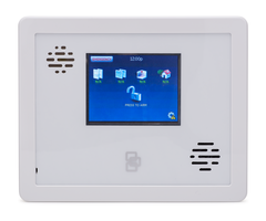
Interlogix Simon XTi - Quick Install Guide
Related Products
Related Categories
Document Transcript
P/N
466-2449
•
REV B
•
17JAN13
Simon XTi Installation Guide
Content
Contact information .......................................................
Description .....................................................................
Installation......................................................................
Connecting hardwired devices......................................
Wiring phone lines.........................................................
Wiring the power transformer ........................................
Resetting memory to factory defaults ............................
Programming.................................................................
Status & Settings screen...............................................
Sensors ........................................................................
Cleaning the touch screen.............................................
Disposal ........................................................................
Specifications...............................................................
Regulatory information .................................................
Contact information
www.utcf
ireandsecu
rity.com
or
www.int
erlog
ix.com
For customer support, see
www.int
erlog
ix.com
/custo
mer-su
pport
Description
This is the
Instal
lation Gu
ide
for the
Simon
XTi
system
(mod
els
600-105
4-9
5R-
12 and
600-10
54-95R
-12-CN).
Table 1
: S
ensors and recommended sensor groups
Device
Part number
Recommended
sensor group
Indo
or mo
tion se
nsor
60-6
39-95
R,
60-8
07-95
b
15, 1
7, 1
8, 20, 2
8, or
32
Entr
y/exit door
60-362
N-10-319.5
10
Interior door
60-362
N-10-319.5
14
Doo
r/Window sensor
60-362N-10-319.5
13
Smoke
sensor
TX-6
010-01-1
c
26
Glassbreak sensor
60-8
73-95
b
13
Device
Part number
Recommended
sensor group
4-Button Key fob
600-10
64-95R
b
01
Simon XT
Talking
Touch
Screen
60-9
24-
3-XT-2WTTS
b
60-9
24-R
F-TS
d
00, 0
1, 0
4, 05, 0
6, or
07
Simon XT
Talking
Touchpad
60-9
24-
3-XT
b
01
Carb
on Monoxide
alarm TX
-6310-01-1
b
, 6
00-
6520-95
b
34
a.
Not ce
rtified
as a
primary protection circ
uit for UL-listed syste
ms
and
is for supplement
ary
use only.
b.
Ha
s not b
een
investigated by U
L.
c.
Re
quired for UL-listed residential
fire alarm ap
plic
atio
ns.
d.
The TWTTS has been ve
rified for
use
by
ETL. Neither th
is de
vice
nor other devices that employ the UTCFS
80 Bit Enhanced
Pr otocol have been
inves
tig ated for
use
by UL.
Note
: These sensor grou
ps
are only reco
mmend
atio
ns. The in
staller shou
ld
choose the co
rrect sensor group for
the a
pplication.
Caution:
Do
not
use out
door moti
on sens
ors fo
r in trusion
protection.
Installation
Pa
nel location
Locate the panel where alarm sounds can be heard and where
the
pan
el will
be
eas
ily
accessible
for op
erat
ion
. Do not inst
all the
panel near a window or door where it can be reached easily by an
intrud
er.
1
1
1
2
3
4
4
4
5
7
9
9
10
10
© 2012 UTC Fire & Security Americas Corporation, Inc.
Interlogix is part of UTC Climate Controls & Security,
a unit of United Technologies Corporation. All rights reserved.
Mounting
Figure 1:
XTi chassis and trim ring
A
B
C
D
To mount the panel on a wall:
1. Lay the panel flat on a table.
2. Remove trim ring (B in
Figure 1
above
) from panel by lifting
at notch
(C in
Figure 1
above
).
3. Separate the panel chassis from the mounting plate by
lifting up on the tabs (A in
Figure 1
above
) and swinging
the chassis open.
4. Choose a panel location.
5. Run all necessary power, phone,
siren, and hardwired
contact wires to the desired panel location.
When choosing the AC outlet location for the AC power
transformer, make sure the outlet is not controlled by a
switch or that it is not part of a ground fault circuit interrupt
(GFCI).
6. Hold the mounting plate
against the wall and mark the
mounting hole locations (
Figure 2
below
) with a pencil.
Note:
Mar k both mounting holes in the middle of the
mounting slot. This will allow better adjustment of the
panel before securing it to the wall.
Figure 2: Mounting holes
Wiring knockout
Mounting hole
M
ounting hole
7. Secure the mounting screws (provided) to the locations on the
wall marked in step 6. Do not tighten the screws. Leave
enough clearance to mount the mounting plate.
Note:
Use wall anchors if no studs are present.
8. Mount the mounting plate to the wall. Insert the top mounting
hole first, then the bottom hole. Adjust the fit to make sure the
mounting plate is level. Hold th
e mounting plate in place and
tighten the screws.
9. Hang the panel chassis on th
e mounting plate at the plastic
hinges, swing the chassis up to the mounting plate and
engage at the tabs (A in
Figure 1
above
).
1
0. Reattach the trim ring.
Connecting hardwired devices
The panel has five screw terminal
s, two battery terminals, and two
telephone connections. The scre
w terminals connect the AC
power, sirens, and/or
hardwired detectors.
Figure 3
: Wiring terminals
HW1 I/O
HW1&
2
D
C out
HW2 i
n
9V
A
C in
9V
A
C in
Program sensors and devices before you install them. Follow the
instructions in ³
Sensors
́ on page 7 to add the sensors to panel
memory.
The HW1 I/O terminal is dual purp
ose and can be used for either
siren or hardwired contact connections. The HW2 in terminal is an
input only.
2
Simon X
Ti Installation Guide
Interior sirens
From the factory, the HW1 I/O input (terminal 1) is set up for
interior siren operation (status and alarm sounds). The
HW1&2 DC out (terminal 2) provides
the positive (+) voltage.
Note:
The total current available from the HW1&2 DC out terminal
is 250 mA at up to 120ºF (49ºC). A 24-hour battery standby for UL
requirements will be met with a maximum load of 250 mA.
With Hardwired Siren Su
pervision turned on, sirens connected
to HW1 I/O are supervised and require a 4.7-kohm resistor in
the circuit. If this terminal is not used, turn Hardwired Siren
Supervision off.
Exterior sirens
For an exterior siren, change the HW1 setting in the System
Options programming me
nu. See wiring diagram.
Note:
Not investigated for and may not be used in a UL Listed
installation.
Hardwired contacts
You can c
onnect hardwired reed switches (normally closed loop
only) to HW1 I/O (if not being used for a hardwired siren) and/or
HW2 in (terminal 3).
Connect only normally closed (NC) reed switches to HW1 I/O
and/or HW2 in. Other types of hardwired detectors should not be
used.
The total resistance of the wired loop must not exceed 3 ohms.
This allows you to use up to 200 ft. (61 m) of two-conductor, 22-
gauge stranded wire.
Connect hardwired reed switches
to the panel using a 47-kohm
resistor (not a 4.7-kohm resistor) as shown in
Figure 4
below
.
The re
sistor must be connected at the last switch in the circuit.
Figure 4
: Normally closed hardwired reed switches
HW1 I/O
47 kohm resistors
HW1&2
DC out
HW2 in
9VAC in
9VAC in
Note:
Do not install the resistor at the panel terminals. This
does not provide supervision of the wire.
Wiring phone lines
You can connect a phone line to the panel for systems monitored
by a central monitoring station or systems that notify users by a
voice event notification.
DSL (digital subscriber line) allows the use of multiple devices on a
single phone line simultaneously
. For DSL environments, connect
the panel line-in jack to an available phone jack on the premises.
You might also need an inline filter to ensure panel reporting is
successful.
Note:
Avoid connecting the panel to
a standard phone (voice) line,
as other devices on the line can prevent reports from going
through.
Full line seizure
F
ull line seizure allows the panel to take over (seize) the phone line,
even if another device on the line is in use. This method requires
that the panel be wired before
all other phones, answering
machines, computers, or other de
vices on the phone line. You may
need to verify the line seizure for UL installations.
Use the RJ31X (CA-38A) jack when wiring for full line seizure. You
can then quickly and easily disc
onnect the panel from the phone
line in case the panel disables th
e phone line due to
a malfunction.
To wire full line seizure with an RJ31X:
1. Run a four-conductor cable fr
om the premises Telco block to
the RJ31X.
2.
Connect the
four-conductor
cable wire to the RJ31X.
3. Disconnect the green and re
d premises phone jack wires
from the Telco block and splice them to the four-conductor
cable black and white (or yello
w) wires. Use weatherproof
wire connectors for these splices.
4. Connect the four-conductor ca
ble green and red wires to the
Telco block TIP (+) and
red to RING (-) posts.
5. Connect the phone cord included with the panel to the RJ31X
and the panel LINE jack.
Full line seizure wiring with one premises phone
If
a single phone is all that exists on the premises, full line seizure
can be accomplished without an RJ31X.
1. Disconnect the phone from th
e premises phone jack and plug
it into the panel PHONE jack. This jack is disconnected
automatically whenever the panel reports.
2. Connect the included phone co
rd to the panel LINE jack and
the premises phone jack.
If a customer adds phones or other phone devices to another
phone jack, full line seizure no longer exists. Inform them to
Simon X
Ti Installation Guide
3
contact you if they want to add a phone or other device so that
you can rewire for full line seizure by adding an RJ31X.
Wiring the power transformer
Connect the power transformer to the two 9 VAC in terminals (4
and 5) on the panel. Do not plug in the transformer at this time.
When applying power to the panel, connect the battery first, and
then plug in the AC power transf
ormer. This sequence prevents a
battery fault condition.
Note:
System can only be powered up using AC power, not
battery power. The red battery icon may appear when the system
first powers up and will dis
appear after some time.
To remove and install the backup battery (6 VDC, 2.1 Ah):
Note:
It is recommended that the backup battery be replaced
every 3-5 years.
1. Remove AC power from the panel.
2. Disconnect the existing battery from the battery connector.
3. Remove the existing battery by reaching under the battery
with a finger and pulling up.
Note:
Do not try to push the plastic latch back to remove the
battery.
4. Insert the new battery into
the battery compartment and
snap into place.
5. Plug the battery connector into the panel.
Caution:
Do not connect the battery un
til you are ready to power
up the panel.
Resetting me
mory to factory defaults
If you need to reset memory to factory defaults, follow the steps
below.
To reset the panel to factory defaults:
1. Remove the trim ring.
2. Open the panel chassis.
3. Unplug the transformer and disconnect the battery.
4. Press and hold the
reset button (D in
Figure 1
on page 2
)
on th e left side of the panel.
5. Plug in the transformer to the panel while holding the reset
button and keeping the panel cover open.
6. Release the button.
7. Plug in the battery and close the panel chassis.
8. Replace the trim ring.
Applying AC power
M
ake sure the outlet is not controlled by a switch or that it is not
part of a ground fault circuit interrupt (GFCI).
Note:
For Canadian installations, plug the transformer into the
wall outlet.
1. Remove the center screw from the outlet cover plate and
hold the cover plate in place.
WARNING:
Use extreme caution when securing the
transformer to a metal outlet cover. You could receive a
serious shock if a metal outlet cover drops down onto the
prongs of the plug.
2. Plug the transformer into the lower receptacle of the outlet so
that the hole in the transforme
r tab lines up with the outlet
cover screw hole.
3. Insert the cover plate screw through the transformer tab and
the outlet cover plate. Tighten the screw.
Note:
Upon initial installation, the battery may not be fully
charged for as long as 36 hours. A low battery icon will be
present and trouble beeps will sound until the battery is
sufficiently charged. After the initial charge, should the panel
lose AC Power and experience
a low battery condition, the
icon will appear and trouble b
eeps will sound unless silenced.
You can silence trouble beeps by:
•
Arming or disarming the system.
or
•
Pressing the STATUS & SETTINGS icon and pressing
LISTEN next to Panel Status.
This will disable the sounde
r for 4 hours but the trouble
indication will remain until the battery is recharged.
Programming
The control panel provides the main processing unit for all system
functions. The programming of system options and features is
menu-driven.
Table 2
below
describes the panel¶s programming keys and
features.
Table 2: S
imon XTi features and home keys
Item
Description
Piezo siren
Provides alarm beeps and status beeps. Fire and
intrusion alarm beeps are always played at high
volume, w
hile the volume
of status beeps is
programmable.
Touch screen
Provides a graphical user interface for
programming and system operation.
Microphone
Used to communicate with the central monitoring
station after an alarm.
4
Simon XT
i Installation Guide
Item
Description
Speaker
Provides voice output and sounds key beeps. The
panel speaks arming level change, system status,
and voice chime sensor trips. The panel voice is also
used for voice reporting and remote phone control.
To access the emergency screen and select the
appropriate emergency icon (Panic, Police, or Fire),
press EMERGENCY in the top left corner of the
screen.
Time
Displays the current system time.
Depicts the status of the AC power and battery. A
green power cord icon represents AC power to the
system. A red battery icon represents low battery
power to the system. A green battery icon
represents a charged battery.
This will appear on the home
scree
n in the event of
an alarm. Messages will also display on this icon
describing what caused the alarm. Press this icon
to
cancel the alarm.
These four icons depict the status of the sensors
installed in your system.
A green check indicates sensors are closed or no
recent activity detected. A red exclamation
indicates sensors are open or recent activity has
been detected.
Pressing these icons will open a new screen to
provide more detail.
If the icon shows N/A, your system is not configured
to support that type of sensor.
Press th
is icon to access the Arming Screen.
One of the
se icons will display depending on your
arming level. Press to turn off intrusion/burglary
protection for your system
. Only intrusion/burglary
sensors are disarmed. Environmental sensors, such
as smoke and carbon monoxide detectors, stay
active
at all times. Enter your code in the keypad
screen
that appears. If you enter an incorrect code,
press the Clear icon and enter the correct code.
Press to
access the Status & Settings screen.
Arming errors
If you select an arming option on
the Arm screen, and there is
an arming problem, an arming error message will appear at the
bottom of the screen, indicating what the problem is and how to
correct it. For example, you migh
t see a message that indicates
that you need to close the front door.
Correct the problem as indicated or press Bypass. You will see the
arming countdown message at the bottom of the screen. You can
touch Cancel and enter your code
to stop the arming process.
Status & Settings screen
Entering and exiting the Status & Settings screen
To enter the Status & Settings screen:
Press the Status & Settings icon
on the lower right of the
home screen.
To exit the Status & Settings screen:
Press Close to exit the Status & Settings screen and navigate up
one level.
Note:
The system will automatically return to the main screen
after a period of inactivity.
A gold icon indicates an option is selected.
A blue icon indicates an option is not selected.
Status & Settings Screen navigation
1. Press the up/down arrows to
scroll through the pages. (See
Table 3
below
for Settings screen structure).
2. Press an icon to change the value of an option or enter a
subscreen.
3. Press Close to return to the previous screen.
Table 3: Status & Settings screen structure
Option
How
to
view
Event History
Press th
e Show ic
on to view system events.
Note:
If a # appears in the Event History list, the
event wa
s not sent to the central station.
Direct Bypa
ss
Press th
e Select icon to enter the sensor bypass
screen.
Panel Status
Press the Listen icon to listen to the status of your
securi
ty system. Press Clear to clear the status.
Chime
Press th
e On/Off icon to set the chime feature
On/O
ff.
Note:
This option may or may not appear depending
on panel
programming.
Special Chime
Press th
e On/Off icon to set the special chime
feat
ure
On/Off.
Note:
This option may or may not appear depending
on panel
programming.
Lights
Press
Control to access the Light screen. From there
you ca
n turn On/Off programmed lights.
Note: Has not been investigated by UL.
Door Locks
Press
Control to access the Door Lock screen. From
there you can lock/unlock programmed door locks.
Note:
Has not been investigated by UL.
Voice V
olume
Press t
he arrows to ad
just the speech volume level.
Beep
Volume
Press th
e arrows to adjust the beep volume level.
Brightnes
s
Press t
he arrows to adjust the screen¶s brightness.
Simon X
Ti Installation Guide
5
Option
How
to
view
Option
How
to
view
Default Screen
Use this feature to set this panel¶s screen saver
mode. Select ³Blank ́ to have the screen and LED
g
o dark after a period of inactivity. Otherwise, the
default will be the Home sc
reen and the screen will
always be lit. If AC power is lost, the screen will go
blank after 2 minutes of inactivity to maximize
battery life.
Note:
The screen will automati
cally go blank at
2:00 am daily for 60 minutes.
Calibration
Press the Show icon to enter the calibration screen.
This screen will allow you to recalibrate the touch
screen.
Help
Press the Help icon to access the Help menu.
Set Date/Time
Press Enter to set the date and time.
System Tests
Press Enter to perform a sensor test or system
download.
Press the Access Codes icon to change existing or
add new access codes.
Press the Security icon to turn downloader enable
on/off and to set the account number.
Press the Phone numbers icon to change existing or
add new phone numbers.
Press the Phone Options icon to access the
following phone options:
•
M
anual
phone
test
•
Fail t
o communicate
•
DTM
F
dialing
•
3
00
BPS
enabled
•
Ring
hang
ring
•
Dia
ler
delay
•
Call
waiting
code
Press th
e Sensors icon to access the learn sensor,
edit sensor, and delete sensor options.
Programming
Press t
he Reporting icon to access the following
reporting options:
•
Op
ening
report
•
Clo
sing
report
•
Fo
rce
armed
report
•
AC
power
failure
report
•
Pa
nel
low
battery
report
•
S
ensor alarm
restoral
report
•
24
hour
sensor
tamper
•
Su
pervisory
tamper
report
•
No
usage
report
•
Swin
ger
shutdown
•
Pr
ogramming
report
•
Fire
alarm
verification
Press the Timers icon to access the following timers
options:
•
Entry
del
ay
•
Exit
delay
•
No
activi
ty
timeout
•
Audio
ph
one
test
•
Supervisory
ti
me
•
Alarm
cancel
window
•
RF
time
out
•
Fail to open time
•
Fail to close time
•
Siren
time
out
•
Unvacated
premi
ses
•
Smoke
sup
ervision
Press the Touchpad Options icon to access the
following options:
•
Keyfob no delay
•
Panic
a
larms
•
Remote TP arming
Press the System Options icon to access the
following system options:
•
RF jam detect
•
Demo
mo
de
•
HW1
fu
nction
•
24
ho
ur
clock
Press t
he Siren Options icon to turn on/off the
following options:
•
Pan
el
piezo
beeps
•
Pan
el
voice
•
Pa
nel
piezo
alarm
•
Troub
le
beeps
•
Vo
ice
chime
•
HW
siren
supervision
•
Silent
police
panic
•
Alar
m
report
verify
Press the Audio Verification icon to access the
following audio verification options:
•
Audi
o
mode
•
Fire
shutdown
•
Fire
enabled
AVM
•
Pan
ic
talk
•
VOX
receiver
gain
•
VOX
microphone
gain
•
VOX
microphone
gain
range
•
Ma
nual
microphone
gain
Press t
he System Tests icon to perform a sensor
test, c
ommunication test, or system download test.
Versio
n
Displays the system¶s firmware version, touch
screen version, and copyright information.
Access Programming screen
1. From the Status & Settings screen, press the down arrow to
scroll to the Programming option.
6
Simon XT
i Installation Guide
2.
Press
Enter.
3. Enter the dealer or installer code (see
Table 4
below
) and
press OK.
Note:
You have four seconds
between number presses to
enter the code or you will be returned to the home screen.
Note:
Do not remove the panel power within 30 seconds of
exiting program mode.
Table 4: Simon XTi programming codes
Code
Description
Dealer
code
You c
an use the dealer code to program all system functions,
including high-security options that are not accessible with the
installer code if it is different from the dealer code. Depending
on how
the access code is set, the default dealer access code
is 654321, 54321, 4321 (factory default), or 321. This code can
be use
d for all programming.
Installer
code
De
pending on how the access code is set, the default installer
code is 654321, 54321, 4321 (factory default), or 321. This
code is limited to changing all but the following: Dealer code,
code length, downloader code, phone lock, phone #1, phone
#2, phone 1 report mode, phone 2 report mode, HW1 function.
Access codes
Table 5
below
describes the Access code menu programming
options.
Table 5: A
ccess codes
Function
Default
Description
Dealer
code
4321
You c
an use the dealer code to program all
system
options, including high-security options
that are not accessible wi
th the installer code if
it is di
fferent from the dealer code. Changing the
dealer code
to differ fr
om the installer code will
prevent the installer from viewing certain fields.
If you change the dealer code and enter
program mode with the installer code, the
installer will no longer
be able to see the
following: code length, downloader code, phone
lock, phone #1, phone #2, phone 1 report mode,
phone 2 report mode, HW1 function.
Installer
code
43
21
You c
an use the installer code to program most
installer options, except
for high-security dealer
options.
Master
code
1234
You can use the master code to arm/disarm the
system and to enter user programming and
bypass sensors.
User
codes 1 t
o
8
Bla
nk
Yo
u can use the user codes to arm/disarm the
system
.
Dures
s
code
Bla
nk
You can use the duress code in place of the
master or user code to cause a silent alarm.
Code
length
Four digits
Codes can be three to six digits long.
Sensors
These instructions describe how to
add (learn) sensors, touchpads,
and other system devices in
to panel memory. The panel
recognizes a sensor when you pr
ess a sensor program icon, press
and release a tamper switch, press
a sensor test button, or put a
sensor into alarm.
Table 6
below
describes the programming
m
ethod for each device.
Note:
If you are installing a sensor on a gun case, jewelry box, or a
similar case, and the sensor is active in level one, you must direct
bypass the sensor to avoid putting the panel into alarm when the
sensor and the magnet are separated.
Mounting Recommendations:
•
Where possible, install sensors within 100 feet (30 m) of the
receiver. While a transmitter and receiver combination may
have an open-air range of 500 feet (152 m) or more, the
environment at the installation site may have a significant
effect on operational range. Ch
anging a sensor or receiver
location can improve wi
reless communication.
•
Avoid mounting sensors or receivers in areas where they will
be exposed to moisture or where the operating temperature
range will exceed the specified range (10 to 120 °F).
•
Avoid mounting the sensor or
receiver in areas with a large
quantity of metal or electrical wiring. For example: within 1
meter of AC distribution panel
(fuse box), HVAC duct work
•
Avoid mounting the sensor or receiver directly on metal.
•
The Simon XTi system should not be mounted within 3 meters
of any other RF equipment (RF music system transmitter,
wireless router/modem, etc.).
Note:
Refer to specific sensor installation instructions for complete
operation and testing details.
Table 6: Device p
rogramming
Device
To
program
Door/window
sensor
Press the button on the top of the sensor (cover
removed) or trip the tamper.
Motion sensor
Press the button on the back of the sensor (mounting
plate removed) or trip the tamper.
Smoke detector
Trip the tamper, pr
ess the test button, remove the
detector from its base, or put the smoke detector into
alarm.
Hardwired sensor
Separate the sensor from its magnet.
CO al
arm
Trip the wall tamper by removing the sensor body from
the m
ounting plate.
Simon XT talking
touch screen
1. Press the Settings icon.
2. Press the Down arrow until the Clear and Enroll icon
appears.
3. Press the Clear and Enroll icon. The touch screen
should indicate it is waiting for enrollment.
Simon X
Ti Installation Guide
7
Device
To
program
Simon XT talking
touchpad
Press the Lights off button on the touchpad six times
i
n
rapid succession. On the sixth press, the touchpad
makes a longer beep.
Key fob
Press the lock and unlock buttons at the same time.
To learn (program) a sensor:
1. From the Programming screen, enter the access code from
the codes listed in
Table 5
on page 7
. The display shows
each entered access
code
digit as a dot.
2. Press OK. You are now in
the programming screen.
3. Press Sensors.
4. Press Learn Sensor.
5. Trip the sensor (see Table 6
on page 7
). The Edit Sensor
screen will appear. If no further action
is required (change
sensor name, number, or group) proceed to step 8. To exit,
press Close repeatedly.
6. To change the sensor name,
number, or sensor group press
the appropriate Edit icon and mo
dify the value. To change
the sensor text, press the appropriate Edit icon, then choose
the item you would like to change.
7. Press Save to keep the new sensor, or Cancel to abort
learning this sensor into the system (both of these choices will
return you to step 5).
8. To exit, press Close repeatedly.
Sensor Naming
Please us
e the following gu
ide when naming sensors:
•
Sensor names must have the word ³window ́ or ³door ́ from
the text library to interact with the touch screen Door and
Windows icons on the Main screen.
•
On the Edit Sensor name screen in programming, default the
screen to list and not keypad. This gives the user the list of
possible sensor names.
•
The Motion icon is controlled by sensors that are
programmed into the following groups: 15, 17, 18, 20, 28,
or 32.
•
The Property icon is controlled by the following sensors:
•
All sensors learned into Group 43.
•
Sensors that are not named ³window ́ or ³door ́.
•
Sensors not learned into the Motion groups.
•
Sensors that are named keyfob, keychain or touchpad.
Sensor Testing
Test the sensors
after all programming is completed and
whenever a sensor-related problem occurs.
Note:
While the sensor test is a valuable installation and service
tool, it only tests sensor operation for the current conditions. You
should perform a sensor test after any change in environment,
equipment, or programming.
Notify the central station you will be performing a test prior to
starting the test.
To test the sensors:
1. Place all sensors in their
secured (non alarm) state.
2. Access the System Test screen through the Programming
Screen, and then press OK.
3. Enter the dealer or installer code and press OK.
4. Press Sensor Test.
5. All learned in sensors will be displayed on this screen. Press
the arrows to scroll through the pages.
Test your sensors by tripping
them one at a time. The panel
will display the number of transmissions received from
sensors you trip. See
Table 7
below
for specific instructions on
how
to trip each sensor type.
The panel sounds beeps, and the display identifies the tripped
sensor and the number of RF packets received. Each beep
represents one RF packet. Count the number of beeps and
refer to
Table 7
below
for minimum requirements. The panel
displays Sn
#, Name, and Roun
ds Detected (Packets). Scroll
through to make sure all sensor have been tested.
Table 7: Sensor tr
ipping instructions
Sensor
Instructions
Minimum
packets requ
ired
Hardwire contact
Open the hardwire contact.
1
Door/window
Open the secured door or
window.
6 o
f 8
Carbon
monoxide alarm
Press and hold the Test/Hush
button (approximately 5 seconds)
until t
he unit beeps two times,
and then release the button.
6 of 8
Glassbreak
Test with an appropriate glass
break sensor tester.
6 of 8
Motion sensor
Avoid the motion sensor field of
view for 5 minutes, and then
enter its view.
6 of 8
Smoke
Press a
nd hold the test button
until the system sounds
transmission beeps.
6 of 8
Key fob
Press and hold the Lock and
Unlock but
tons simultaneously
fo
r 3 sec
onds.
6 of 8
Simon XT talking
touchpad
Press and hold the two
Emergency buttons
simult
aneously for 3 seconds.
6 of 8
8
Simon XTi Inst
allation Guide
Sensor
Instructions
Minimum
packets requ
ired
Simon XT talking
touch screen
For sensor testing a 1.0. touch
screen,
press and hold the
Emer
gency icon for 5 seconds.
For sens
or testing a 1.1 or greater
touch screen, press the Settings
(gear) icon, scroll down, and then
press the
RF Test icon.
6 of 8
6. Press Close repeatedly to exit.
Sensor Test Failure
If sirens do not beep when a sens
or is tripped, use an RF Sniffer
(60-401) test tool to verify that the sensor is transmitting. Constant
beeps from the RF Sniffer indicate a faulty sensor. Replace the
sensor.
If possible, locate sensors within 100 ft. (30 m) of the panel.
While a sensor may have a range of 500 ft. (152 m) or more
out in the open, the environment at the in
stallation site can have
a significant effect on transmitter range. A change in sensor
location may help overcome adverse wireless conditions and
can potentially be accomplished by the following:
•
Reposition the sensor
•
Relocate the sensor
•
If necessary, replace the sensor
To reposition a sensor:
1. Rotate the sensor and test for improved sensor
communications at 90 and 180 degrees from original
position.
2. If poor communication persists, relocate the sensor.
To relocate a sensor:
1. Test the sensor a few inches from the original position.
2. Increase the distance from th
e original position and retest
until an acceptable location is found.
3. Mount the sensor in the new location.
4. If no location is acce
ptable, replace the sensor.
To replace a sensor:
1. Test a known good sensor at the same location.
2. If the transmission beeps remain below the minimum level,
avoid mounting a sensor
at that location.
3. If the known-good sensor functions, contact UTC Fire &
Security for repair or replacem
ent of the problem sensor.
Sensor Testing Notes:
•
Conduct sensor test in all possible environmental conditions
(For example: interior doors open and closed, HVAC system
on and off, wireless music system turned on and off).
•
Conduct sensor test whenever changes are made to the
installation environment that may impact RF performance
(For example: mirrors insta
lled, metal backed wall paper,
addition of other RF equipment).
•
Sensor testing should be done
before and after permanent
mounting.
Comm Testing
I
f Comm Test is not finished, it will continue to run even if you exit
program mode.
Note:
Complete panel programmin
g before performing comm
testing.
To perform a comm test:
1. Enter the Status & Settings menu.
2. Scroll until System Tests is listed, Press Enter.
3. Enter your master code and press OK.
4. Press Comm Test.
The panel displays if the comm test was successful or not.
Central station communication
Afte
r performing sensor tests, check that the system is reporting
alarms successfully to the central station.
Note:
The communication with the central station test must be
done while NOT in programming mode.
To verify alarm reporting:
1. Call the central station and tell the operator that you will be
testing the system.
2. Arm the system.
3. Test an emergency panic icon
and trip at least one sensor of
each type (fire, intrusion, etc.
) to verify that the appropriate
alarms are working correctly.
There is a 30 second delay.
4. When you finish testing the system, call the central station to
verify that the alarms were received.
Cleaning the t
ouch screen
If necessary, use a soft cloth to clear smudges on the touch
screen. Do not use glass cl
eaner on the touch screen.
Disposal
Dispose of all equipment is accordance with local requirements.
Simon X
Ti Installation Guide
9
Specifications
Power
9 VAC, 60
Hz,
25 VA tr
ansformer minimum
Re
chargeable battery: 6.0 VDC, 2.1
Ah NIMH.
Maximum bat
tery
charging cu
rre
nt
is 120 mA.
Once the battery re
aches a low batte
ry co
ndition,
a trouble signal will be annunciated, indicating
that the
battery
may
no longer support a full
alarm load.
When fully charged, the battery will operate the
panel without AC
power for
24 hours with the
panel
in a nor
mal,
standby condition, followed by
5 minutes in full alarm condition (including the
maximum specified auxiliary load of 250 mA).
Radio
frequency
319.5 M
Hz
Stor
age te
mperat
ure
-29 to 140ºF (-
34 to 60ºC)
witho
ut ba
ttery
14 to 86
ºF (-10 to 30ºC) with ba
ttery one ye
ar
shelf life
Oper
ati ng
temp
erat
ure
32 to 1
20ºF (0 to 49º
C)
Maximum humi
dity
85%
relati
ve humi
dity, nonconde
nsing
Auxiliary power
Unregulated 4.0 to 12.3 VDC, with a maximum of
250 mA
Regulatory information
Some installation may require co
nfigurations dictated by
city/state
codes
, insura
nce
, or Underwriter’s Laboratories (UL).
This se
ctio
n de
scribe
s the
variou
s com
ponen
t and
confi
guration
listings.
Basi
c system:
•
C
ontrol
pane
l: Backup
batte
ry 6 V
2.1 Ah
(34-07
0)
•
Standard Class 2, 9 VAC, 25 VA power transformer
(UTC Fire & Security part 22-155) or Standard, Class 2, 9
VAC, 30 VA (UTC Fire & Security
part 22-153
).
•
Hardwired siren (13-374)
Household burglary alarm system
unit (UL 1023), basic system
pl us
th e fo llowi
ng:
•
Hardwired magnetic co
ntact (1038T) or wirele
ss learn mode
door/window se
nsor (60-670-
95R or
60-3
62
N-1
0-
319.5 or
60-3
62N-
11-3
19.
5)
•
Panel piezo bee
ps set to on
•
Entry del
ay se
t to 45 s
econds
or le
ss
•
Exit dela
y set to
60 s
eco
nds or le
ss
•
RF ti
me-out set
to
24 ho
urs
•
Control p
anel
alarms
turn
ed
on
•
Auto arm set to on
•
Siren t
imeo
ut set to 5
minutes or m
ore
•
Trouble beeps set
to on
•
RF jam dete
ct set
to on
•
Hardwired siren supe
rvisi
on set
to on
•
Exit extension set
to off
•
Quick exit set to off
Household fire warning system (UL 985), basic system plus the
fo llowin
g:
•
Wireless sm
oke se
nsor
60-848-
02-95,
TX-60
10-
01-1
learned
into se
nsor
grou
p 26.
•
Panel piezo bee
ps
turned on
•
Control p
anel
alarms
set
to on
•
Siren t
imeo
ut set to 4
minutes or m
ore
•
Trouble beeps set
to on
•
RF jam dete
ct set
to on
•
Hardwired siren supe
rvisi
on set
to on
•
Smoke
supervision set to on
UL 1635
digital
alarm co
mmuni
cator sy
stem
the
follo
win
g se ttings
are
requ
ired
only if the system is set up for
central
stati
on
reporting:
•
Phone mode 1 set
to “All SIA” or “All CID”
•
Auto
matic pho
ne te
st set to
001
•
RF ti
meout set to 4 ho
urs
•
AC power failure report set to on
•
CPU low battery report set to on
•
Fail
to
communi
cate set
to on
•
Entry delay plus the dialer del
ay
mu
st no
t exceed
60 s
econds
SIA
system req
ui
rements
Verif
ied
to SIA
CP-01-2007
by ETL
, bas
ic sy
stem
, plus if mult
iple
annu
nci
ation
s are required, use
hardwi
red si
ren
13-0
46.
Note:
For U
L 1635 installatio
ns, entry delay plus dialer abort delay
must not exc
eed
60 s
eco
nds.
Table 8 below de
scribe
s progra
mming requirements to meet
ANSI-SIA CP-01.
Table 8: SIA setting requirements
Function
Default setting
Required setting
Entry delay
30 seconds
30 to 240 seconds
Ex
it delay
60 seconds
45 to 240 seconds
Dialer delay
30 seconds
15 to
45 seconds
Auto arm
On
On
Unvacated premises
On
On
Call wa
iting
Off
On
if reporting
to
ce ntral st
ation
and
customer has call
waiting service
Alarm ca
ncel wind
ow
6 mi
nutes
6 to 2
55
minutes,
Off
System test
Enab
led
Enab
led
Communication test
Enabled
Enabled
Exit extension
On
On
Sw
inger shut
down
On (one tr
ip)
On (one tr
ip)
Fire alarm verify
O
ff
On
10
Simon XTi Installation Guide
Simon XTi Installation Guide
11
Function
Default setting
Required setting
Duress/panic code
Disabled
Disabled
Cross zone
Disabled
Disabled for zones with
high pr
obability
of false
alarms
Table 9 below describes nonprogrammabl
e (hard-coded) system
operation, as required
to meet ANSI-SIA CP-01.
Table 9: Nonprogrammable system operation
Function
Operation
Silent exit
All annunciators enabled
Remote arming exit time and
progre
ss annu
nciati
on
All annunciators enabled
Abort annu
nciation
Enabled
Ca
ncel repo
rt a
nnunciati
on
Enabled
Recent closing
Enabled
(2-
minute wind
ow)
Exit error
Enabled
Restoration of
power
Panel resumes operation in same
ar ming st
ate and
disregar
ds alarm
sign
als from sensors for the fir
st 60
seconds af
ter po
wer restor
ation
Ca
ncel alarm
Enter code on
ly
Central station report
ing
Note
: The panel shall not be set or programmed to place a call
to a police
station
number th
at has not been specif
ically
assigned
by that po
lice
station
for
such se
rvice.
Caution:
If call
waiting is
used on a non-call
waiting
line,
successful
conn
ection to
the ce
ntral st
atio
n may be prevented.
The panel has been te
sted with
the fo
llo win
g ce ntral stat
ion
receivers using SIA and Contact ID reporting formats:
Befo
re
beginnin
g inst
allati
on,
inst
allers m
ust
verify that the
cent
ral stati
on is equi
pped
with the
follo
win
g receivers:
•
Radionics D
6600 centr
al stati
on
rece
iver
•
Sur-Gard central station receiver with models SG-DRL2A
and SG-CPM2
•
CS5000 digital alarm communicator receiver
UL
Can
ada
listed insta
llatio
ns
This section describes the requirements for CUL (UL Canada) listed
in stallations.
Canadian standards CSA certified accessories:
•
Standard Class 2, 9 VAC, 30 VA power transformer (UTC Fire &
Secu
rity model 22-153-CN) or Stan
dard
Class 2, 9 VAC, 25 VA,
(U TC Fire & Secu
rity model 22
-155
-CN
).
Residential burglary alarm system
unit (ORD-C1023-1974): basic
system as
descri
bed for
UL
1023
list
ed inst
allations
plus:
•
Hardwired magnetic co
ntact (1038T) or wirele
ss learn mode
door/window se
nsor
(60-67
0)
•
Siren time
out set to six minutes
or more
Resi
dential fi
re
warning s
yst
em co
ntrol
unit (U
LC-S54
5-M
89):
bas
ic
system
as described for UL 985 listed i
nst
allati
ons
plus:
•
Wireless sm
oke se
nsor
60-848-
02-95,
TX-60
10-
01-1
learned
into s
ensor
grou
p 26
•
Siren time
out set to six minutes
or more
FCC comp
lia nce
Thi
s equipme
nt has b
een tested
and fo
un
d to
co
mply wi
th
the
limits for a Class B digital device, pursuant to Part 15 of the FCC
rules
. These limits are designed to provide reasonable protection
against harmful interference when the equipment is operated in a
resi
dent
ial en
vir onment. This equipm
ent genera
tes, us
es,
and
can
radiate radio frequency energy and, if not installed and used in
accordance with the instructio
n manual, may
cause harmful
interference to radio communications.
Changes or modifications not expressly approved by the party
responsi
ble for co
mplian
ce c
ould vo
id the us
er’s
authority to
operate the equipment.
FCC Part 15 registration
num
ber:
B4Z-910
C-SI
MON
IC: 11
75C-910CSIMO
This Class B digital apparatus complies with Canadian
ICES-001.
Cet appareil n
umérique de la classe B est conforme à la norme
NMB-003 du Canada.
Part 68. This equipment
comp
lie s wit
h Pa
rt 68 o
f the
FCC rule
s and
the requirements adopted by ACTA.
FCC registration number: US:
B4ZAK02B559
10
Can
ada:
1175C-
910
CSIXT
Ranger Equivalence 0.
2B
Load Number 0.2
466-2449
Printed in Mexico
- Uploaded