Resideo Honeywell Home LTE-21V - Install Guide Dated 3/19
Related Products
Related Categories
Document Transcript
Document ID 800-25357C Rev. C
– 1 –
LTE
-21V
Module Kit
– Installation Instructions
General Information
The
LTE
-21V
is an
optional communication module intended
for use with the VISTA
-21iP
LTE
and
V21SIALTE
control
s,
and provide cellular radio communication with the AlarmNet
network for de
livery of alarm and other messages to the
monitoring central station.
IMPORTANT!
Use of this module requires an AlarmNet
-I account. If an
account for the control does not yet exist, please obtain
the account information from the central station prior to
programming this module.
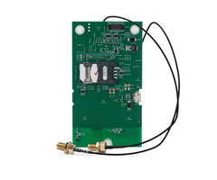
This kit contains the following components:
E
SD SENSITIVE DEVICE -
To discharge any static buildup, briefly touch a chassis ground point before
installing this module. Avoid performing this installation while standing on
a carpeted floor.
NOTE:
The
module
is supplied with the antenna adapter cables
pre-connected to the module.
Installing the module
1. Mount the
Module
Board.
Disconnect power from the control, includ
-
ing the battery, BEFORE installing the
module.
a. Carefully align the module
board over the standoff
holes
and the mating connector
on the VISTA
-21IP
LTE
or
V21SIALTE
control.
Then,
gently push down on the
board near each standoff until it snaps into place and
the connector is fully seated.
b. After
installation, affix the “Contains Transmitter
Module”
FCC
label to the outside surface of the control
panel cabinet so it is visible.
Installing
the
module
on the
VISTA
-21iP
LTE
/V21SIALTE
PCB
- 2-
2.
Install the Antenna Adapter Plate
s
.
a. Punch out the large wiring-hole knockout and the
adjacent smaller knockout from the cabinet’s upper
-
right
and left topside.
b. Position the antenna adapter plate over the large
knockout, aligning the plate’s pin with the smaller
knockout and push until the adapter snaps into place.
c. Remove the nut and washer from the antenna adapter
cable then secure the cable’s SMA connector to the
adapter plate with the washer and nut as shown.
3.
Install the Antenna
s
.
RF Exposure
Warning
–
The antenna(s) used for this tr
ansmitter must be
installed to provide a separation distance of at least 7.8 inches (20
cm) from all persons and must not be co-
located or operating in
conjunction with any other antenna or transmitter except in
accordance with FCC multi
-transmitter produc
t procedures.
Mise en Garde
Exposition aux Frequences Radio:
La/les antenne(s) utilisée(s)
pour cet émetteur doit/doivent être installée(s) à une distance de
séparation d'au moins 20 cm (7,8 pouces) de toute personne et ne
pas être située(s) ni fonctionner parallèlement à tout autre
transmetteur ou antenne, excepté en conformité avec les
procédures de produit multi transmetteur FCC et ISEDs
The antennas mount
directly onto the antenna adapter cable
at the antenna adapter plate.
Carefully align the antenna’s connector over the SMA
connector protruding from the adapter plate, then screw it
down (clockwise) until it is finger tight. Do not over tighten.
*
LTE
-21V
Initial Power Up
: Upon initial power up, the communicator LEDs blink in repeated sequence from
top to
bottom indicating network initialization.
Green (REG)
Yellow (TX/RX)
Red (FAULT)
This sequence may take up to 15 minutes.
Do not reset power during this time.
When initialization is complete, the Signal Quality display LEDs will light and the
yellow and red LEDs may blink (per their
respective functions).
After initial network setup, subsequent resets or power ups can take up to 90 seconds.
Checking
Signal
Quality
The Signal
Quality
/ Mode and Status LEDs normally display
the module’s signal q
uality
. LED 1 (red LED on the top) will
be lit to indicate that the display is in signal quality
mode, and
the other LEDs indicate signal strength (lowest to highest,
from left to right) between the module and the receiving
tower.
•
This allows you to immediately determine if the
desired mounting location has sufficient signal
strength for proper operation.
•
For proper operation, look for at least 3 bars lit solid.
NOTE:
The module must be registered to transmit messages
to AlarmNet and your central station.
The following are tips for maximizing signal
quality
:
•
The best
signal
quality
can usually be found on an
exterior wall at the highest point in the building.
Avoid the basement.
•
Maintain at least 12 inches clearance between
antenna and steel I
-beams, HVAC ducts, metal
studs, steel roofs, exterior walls with metalized
insulation or aluminum siding and other large metal
objects.
If a consistent two
bars cannot be found, the control cabinet
may have to be moved to an area of better reception.
- 3-
Programm
ing the Module
The module’s parameters are programmed using the control’s
*29 Menu mode. The programming procedure can be found
in the control’s Programming Guide.
To program the module,
press
∗
29 while in
Programming mode, then follow the prompts.
Mo
nitoring
Status &
Network Status
LEDs
Status LEDs
There are three Status LEDs on the VISTA
-21iP
LTE
/
V21SIALTE
PC board used to indicate message and device
status:
•
STATUS, green
•
MESSAGE, yellow
•
FAULT, red
Each LED can have four different states –
ON, OFF, FAST
BLINK and SLOW BLINK.
Status LED Meanings
COLOR/LED
DESCRIPTION
Green
Status
On
–
module NOT registered
Off – module is registered
Fast Blink –
Download session with Compass in
progress
Slow Blink – In unison with yellow LED –
Registrati
on in progress.
Yellow
Message
On
–
Message transmission pending.
Quick Periodic Blink – Normal.
Fast Blink –
Message waiting for network ACK.
Slow Blink –
In unison with green LED –
Registration in progress.
Red
Fault
On
–
No contact with network.
Off
– Normal.
Slow Blink – Loss of contact with panel (ECP
fault).
Fast Blink – No network contact AND loss of
contact with the panel.
All
Fast Blink
–
In unison with the RSSI Bar Graph
LEDs – Hardware Error. Call the
AlarmNet Technical Assistance
Center.
Network Status
LEDs
Status Indicator Switch
Press and hold the Status LED Indicator Switch to change
the LED functions to view the network carrier status. When
the switch is held down, LED 1 (top red LED) will be off, and
the other LEDs have the following meanings shown in the
Network Status LED Meanings table (See diagram for
specific functions).
Signal Strength and
Network Status LED Meanings
COLOR
LABEL
INDICATION
Red
Signal
Quality
on = signal
quality
display
off = status display
Yel
mode
off = modu
le operating in ECP mode
Green
Mode
off = module operating in ECP mode
Green
Web
web connection status
Green
Cell
Cell
service availability
Green
Cell
network carrier registration status
Module Cellular Status
LED
The
cellular status
LED
is located
on the module’s
PC board
:
Cellular Status LED
Connected to Cell network (Registered idle or in a data call)
–
Slow Blinking (period: 1s On / 1s Off
)
Searching / Not Registered / Turning Off
–
On
Module is not powered up
–
Off
Signal
Quality
and
Network
Status LED locations
– Network
Status LED Functions Table
Registering the Control with AlarmNet
Normally, registration with AlarmNet is done at the time the
control is installed. If the module is being installed as an add-
on, the control must be re-
registered.
Follow the registration procedure in the control’s Installation
and Setup Guide. A summary of registration steps follows.
Register the control by using one of these methods:
Alpha Keypad using *29 Menu mode
1.
Enter *29 Menu mode, select Diagnostic mode, then
use the [
↑
]
shift-
B
command (D key followed by the
B key). The registration message is sent
(“Registering” displayed) and the control waits for the
acknowledgment.
2.
“Registration SUCCESS” displayed, indicating
successful re
gistration.
Test Switch on control’s PCB (triple
-click)
1.
Click the switch three times.
2.
Watch the Status LEDs: The Message (yellow) LED
and the Status (green) LED will blink slowly in unison
while registration is in progress.
3.
When registration i
s complete, the Status (green)
LED goes out.
AlarmNet 360
website
See paragraph at right.
By phone
1.
Call 1-
800-
222-
6525
You will need the following information:
•
MAC ID and MAC CRC number (found on the label
on control’s PC board).
•
Subscriber i
nformation (provided by the central
station), including a city code, CSID, and a
subscriber ID.
•
Activation ID (AID) and AID CRC numbers (found on
the label on the module or on its carton)
2.
When instructed to do so, triple-
click the Test switch
to com
plete the registration.
Registering through AlarmNet Direct Website
To register via AlarmNet 360 Website, please go to:
www.alarmnet360.com
Log in and follow the on-
screen prompts.
Please have the following information available:
•
Primary City ID (two
-digit number provided by central station)
•
Primary Central Station ID (two
-digit hexadecimal number provided by
central station)
•
Primary Subscriber ID (four
-digit number provided by central station)
•
MAC ID and MAC CRC number (located on outside of box
and on
label on control’s PC board)
•
AID and AID CRC numbers (found on the label on the module or on its
carton).
Once the control is registered, you may log out of the AlarmNet 360
website.
FCC / IC STATEMENT
The user shall not make any changes or modi
fications to the equipment
unless authorized by the Installation Instructions or User's Manual.
Unauthorized changes or modifications could void the user's authority to
operate the equipment.
CLASS B DIGITAL DEVICE STATEMENT
This equipment has been tested and found to comply with the limits for a
Class B digital device, as defined by FCC Rules Part 15.105. The Class B
Digital Device statement can be viewed at:
https://customer.resideo.com/en-
US/support/residential/codes-
and
-
standards/FCC15105/Pages/default.aspx
This device complies with Part 15 of the FCC Rules, and RSS210 of Industry
Canada. Operation is subject to the following two conditi
ons: (1) This device
may not cause harmful interference, and (2) This device must accept any
interference received, including interference that may cause undesired
operation.
Cet appareil est conforme à la partie 15 des règles de la FCC & de RSS 210
des In
dustries Canada. Son fonctionnement est soumis aux conditions
suivantes: (1) Cet appareil ne doit pas causer d’interférences nuisibles. (2)
Cet appareil doit accepter toute interférence reçue y compris les interférences
causant une réception indésirable.
Responsible Party / Issuer of
Supplier’s Declaration of Conformity:
Ademco Inc., a subsidiary of Resideo
Technologies, Inc., 2 Corporate
Center Drive., Melville, NY 11747,
Ph: 516
-
577
-
2000
Partie responsable / Émetteur de la
déclaration de conformité du
fournisseur :
Ademco Inc., une filiale
de Resideo Technologies, Inc., 2
Corporate Center Drive., Melville, NY
11747, Tél. 516
577
-
2000
ANTENNA SPECIFICATIONS
Type:
Broadband External LTE/Cellular
Antenna
VSWR:
<
2.5:1
Polarization:
Vertical
Impedance:
50 Ohms
Gain (Peak):
1.18dBi ~ 4.0dBi
Connector Type:
SMA male
Current Drain (measured at the Vista
-
21iPLTE AC input):
60mA average standby,
580mA (rms) peak transmit
Frequency Bands
LTE
Band 2
LTE
Band 4
LTE
Band 5
LTE
Band 12
LTE
Band 13
WCDMA
Ban
d II
WCDMA
Band V
LTE
-
21V
X
X
X
X
X
X
X
IMPORTANT NOTE ABOUT EXTERNAL ANTENNAS
Antenna may only be installed or replaced ONLY by a professional installer.
TO THE INSTALLER
The external an
tenna gain shall not exceed 6.94
dBi for 700 MHz and 850MHz, 6.00 d
Bi for 1700 MHz, and 9.01
dBi for 1900 MHz. Under no conditions may an
antenna gain be used that would exceed the ERP and EIRP power limits as specified in FCC Parts 22H, 24E and 27
.
SUPPORT, WARRANTY, & PATENT INFORMATION
For the latest documentation and online support information, please go to:
https://mywebtech.honeywellhome.com/
For the latest warranty information, please go to:
https://www.security.honeywellhome.com/hsc/r
esources/wa/index.html
For patent information, see
https://www.resideo.com/patent
MyWebTech
Warranty
Patents
The product should not be disposed of with other household waste. Check for the nearest
auth
orized collection centers or authorized recyclers. The correct disposal of end-
of-life
equipment will help prevent potential negative consequences for the environment and human
health.
This product is manufactured by Resideo Technologies, Inc.
The Honeywell Home
Trademark is used under license from Honeywell International Inc.
Ê800-25357CÆŠ
800
-
2
5357
C
3/19 Rev
C
2 Corporate Center Drive, Suite 100
P.O. Box 9040, Melville, NY 11747
201
9 Resideo Technologies, Inc.
www.resideo.com
- Uploaded