Resideo PROLTE Communicator - Install Guide - Dated 03/19 Rev. F
Related Products

Related Categories
- LTE Cellular Communicators
- Cellular Alarm Communicators
- Verizon LTE Cellular Communicators
- LTE Cellular Communicators
- Cellular Alarm Communicators
- AT&T LTE Cellular Communicators
Document Transcript
Sluf
PROLTE Series Wireless
Communication
Module
s
Installation and Setup Guide
General Information
The Communication Modules allow the control panel t
o communicate with the Central Station via the cell
ular radio network. The PROLTE
Series includes the following models:
PROLTE-A / PROLTE-A2 (US/Canada, AT&T Network)
PROLTE-V / PROLTE-V2 (US, Verizon Network)
PROLTE-CN (Canada, Bell Network)
The
PROLTE Series
wireless communications module is intended to prov
ide compatible PRO Series control panels with a cel
lular
connection with the central monitoring station. The
module connects directly to the control panel and
is powered via the control panel’s
connection. Refer to the applicable Control Panel's
Installation and Setup Guide for additional inform
ation.
Compatible Control Panels:
PROA7PLUS/PROA7 Series
PROA7PLUSC/PROA7C Series
NOTE
: Control Panel Firmware Revision 3.1297.xxx or lat
er is required for the PROLTE-A2 or PROLTE-V2 modul
e.
Installing the Module in the PROA7PLUS/PROA7 Series
!
Ensure that all electrical power is removed from th
e control before installing the module. Unplug the
power supply and disconnect the backup battery.
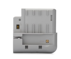
1. Affix the provided FCC/IC on the control’s case
back
(refer to Figure 1 for location).
2. If the Control Panel is not powered up proceed t
o step
7. If the Control Panel is powered up, disarm the
system and wait 30-60 seconds:
3. Unplug the power supply.
4. Remove the screw securing the control to the wal
l or
desk mount.
5. Remove the control from the wall or desk mount.
6. Disconnect the battery.
Figure 1. FCC/IC Label Location
7. Remove the left side from the control.
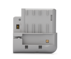
8. Insert the PROLTE Series module into the slot on
the
left side of the control as shown in Figure 2 and e
nsure
the receptacle is securely seated on the control’s
edge
connector.
9. Secure with the screw.
10. Install the left side cover.
11. Connect the battery.
12. Install the control on the wall or desk mount.
13. Plug the power supply into a 24-hour, 110VAC
unswitched outlet.
PROLTE-SERIES
MODULE
COVER
MACHINE
SCREW
QS-057-V0
EXT
INT
Figure
2.
Installing the
PRO
LTE Module
Programming
1. Programming associated with the PROLTE Series mo
dule is accomplished, as part of the control panel
programming. Refer to the
control panel installation and setup guide for addi
tional information.
2. When programming is complete, perform a Communic
ations Test.
Using an External Antenna
If adequate signal strength cannot be achieved with
the internal antenna, an external antenna can be e
mployed. A PROLTE-ANT or CELL-
ANT3DB kit with an adapter cable, clamp, and bracke
t will be required. A connection diagram with the a
dapter kit and a typical antenna is
provided with the kit.
IMPORTANT NOTE ABOUT EXTERNAL ANTENNAS
If an external cellular radio antenna is used, the
antenna may be installed or replaced ONLY by a prof
essional installer.
To the Installer
PROLTE-A: The external antenna gain shall not excee
d 6.63 dBi for 700MHz and 850MHz, 6.0 dBi for 1700M
Hz and 8.5 dBi for 1900MHz. Under no
conditions may an antenna gain be used that would e
xceed the ERP and EIRP power limits as specified in
FCC Parts 22H, 24E and 27.
PROLTE-V: The external antenna gain shall not excee
d 6.94 dBi for 700MHz, 6.0 dBi for 1700MHz and 9.01
dBi for 1900MHz. Under no conditions may an
antenna gain be used that would exceed the ERP and
EIRP power limits as specified in FCC Parts 22H, 24
E and 27.
PROLTE-CN: The external antenna gain shall not exce
ed 6.63 dBi for 700MHz and 850MHz, 6.0 dBi for 1700
MHz and 8.51 dBi for 1900MHz. Under no
conditions may an antenna gain be used that would e
xceed the ERP and EIRP power limits as specified IC
RSS-130, RSS-132, RSS-133, and RSS-139.
PROLTE-A2 / PROLTE-V2: The external antenna gain sh
all not exceed 5.00 dBi. Under no conditions may an
antenna gain be used that would exceed the
ERP and EIRP power limits as specified in FCC Parts
22H, 24E and 27.
Specifications
PROLTE-A / PROLTE-A2
PROLTE-V / PROLTE-V2
PROLTE-CN
Dimensions
: ......................................... 2.85in
(72.39mm) W x 2.8in (71.12mm) L x 0.675in (17.15mm)
D
Current Drain
: Idle ............................. 30mA, standby
Transmit ..................... 490mA, max transmit
(PROLTE-A / PROLTE-V / PROLTE-CN)
860mA, max transmit (PROLTE-A2 / PROLTE-V2)
Input Voltage:
...................................... 5V (provide
d by the control panel)
Environmental
Operating Temperature: ........................ -10
°F (-23°C) to 131°F (55°C) (for compliance agency 3
2°F (0°C) to 120°F (49°C)
Storage Temperature: ............................ -
40°F (-40°C) to 158°F (70°C)
Humidity: .........................................
...... 10 to 90% relative humidity, non-condensing
(for compliance agency 0% to 85%)
LTE Bands:
.......................................... PROLTE-
A Supports LTE Bands 2, 4, 5 and 12
PROLTE-A2 Supports LTE Bands 2, 4, 12, 14 and 66
PROLTE-V Supports LTE Bands 2, 4 and 13
PROLTE-V2 Supports LTE Bands 4 and 13
PROLTE-CN Supports LTE Bands 2, 4, 5 and 12
Antenna
................................................ M
ulti-Band diversity antennas
External Antenna Kit
: .......................... PROLTE-ANT or CELL-ANT
3DB
FEDERAL COMMUNICATIONS COMMISSION ISED STATEMENTS
The user shall not make any changes or modification
s to the equipment unless authorized by the Install
ation Instructions or User's Manual. Unauthorized
changes or modifications could void the user's auth
ority to operate the equipment.
FCC CLASS B STATEMENT
This equipment has been tested to FCC requirements
and has been found acceptable for use. The FCC requ
ires the following statement for your
information:
This equipment generates and uses radio frequency e
nergy and if not installed and used properly, that
is, in strict accordance with the manufacturer's
instructions, may cause interference to radio and t
elevision reception. It has been type tested and fo
und to comply with the limits for a Class B computi
ng
device in accordance with the specifications in Par
t 15 of FCC Rules, which are designed to provide re
asonable protection against such interference in a
residential installation. However, there is no guar
antee that interference will not occur in a particu
lar installation. If this equipment does cause inte
rference to
radio or television reception, which can be determi
ned by turning the equipment off and on, the user i
s encouraged to try to correct the interference by
one or
more of the following measures:
• If using an indoor antenna, replace it with a qua
lity outdoor antenna.
• Reorient the receiving antenna until interference
is reduced or eliminated.
• Move the radio or television receiver away from t
he receiver/control.
• Move the antenna leads away from any wire runs to
the receiver/control.
• Plug the receiver/control into a different outlet
so that it and the radio or television receiver ar
e on different branch circuits.
• Consult the dealer or an experienced radio/TV tec
hnician for help.
Responsible Party / Issuer of Supplier’s Declaratio
n of Conformity: Ademco Inc., a subsidiary of Resid
eo Technologies, Inc., 2 Corporate Center Drive.,
Melville, NY 11747, Ph: 516-577-2000
Partie responsable / Émetteur de la déclaration de
conformité du fournisseur :
Ademco Inc., une filiale de Resideo Technologies, I
nc., 2 Corporate Center
Drive., Melville, NY 11747, Tél. 516 577-2000
ISED CLASS B STATEMENT
This Class B digital apparatus complies with Canadi
an ICES-003.
Cet appareil numérique de la classe B est conforme
à la norme NMB-003 du Canada.
FCC / ISED STATEMENT
This device complies with Part 15 of the FCC Rules,
and ISED’s license-exempt RSSs. Operation is subje
ct to the following two conditions: (1) This device
may not cause harmful interference (2) This device
must accept any interference received, including in
terference that may cause undesired operation.
Cet appareil est conforme à la partie 15 des règles
de la FCC et exempt de licence RSS d’ISED. Son fon
ctionnement est soumis aux conditions suivantes:
(1) Cet appareil ne doit pas causer d’interférences
nuisibles. (2) Cet appareil doit accepter toute in
terférence reçue y compris les interférences causan
t une
réception indésirable.
!
RF Exposure Warning
The antenna(s) used for this transmitter must be in
stalled to provide a separation distance of at leas
t 7.8 inches (20 cm) from all persons and
must not be co-located or operating in conjunction
with any other antenna or transmitter except in acc
ordance with FCC and ISED multi-
transmitter product procedures.
Mise en Garde
Exposition aux Frequences Radio:
La/les antenne(s) utilisée(s) pour cet émetteur do
it/doivent être installée(s) à une distance de sépa
ration
d'au moins 20 cm (7,8 pouces) de toute personne et
ne pas être située(s) ni fonctionner parallèlement
à tout autre transmetteur ou antenne,
excepté en conformité avec les procédures de produi
t multi transmetteur FCC et ISEDs.
The product should not be disposed of with other ho
usehold waste. Check for the nearest authorized col
lection centers or authorized recyclers. The correc
t
disposal of end-of-life equipment will help prevent
potential negative consequences for the environmen
t and human health.
Any attempt to reverse-engineer this device by deco
ding proprietary protocols, de-compiling firmware,
or any similar actions is strictly prohibited.
REFER TO THE INSTALLATION AND SETUP GUIDE FOR THE C
ONTROL WITH WHICH THIS DEVICE IS USED FOR LIMITATIO
NS OF THE
ENTIRE SYSTEM.
For Support visit: www.resideo.com.
For Warranty information visit: www.security.honeyw
ellhome.com/warranty.
This product manufactured by Resideo Technologies,
Inc. and its affiliates.
The Honeywell Home Trademark is used under license
from Honeywell International Inc
2 Corporate Center Drive
Melville, New York 11747
© 2021 Resideo Technologies, Inc
www.resideo.com
800-25165F 3/19 Rev. F
- Uploaded