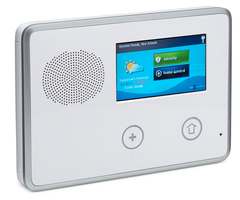
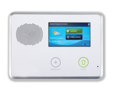
2GIG Go!Control - Quick Programming Guide
Related Products
Related Categories
Document Transcript
GETTING STARTED
To enter the control panel’s System Configuraton module to
program sensor zones and modify setngs:
1. At Home screen, tap logo in lower-right corner.
Enter: Master Installer Code.
Tap: System Configuraton.
Or
2. At Home screen:
Tap: Security > Menu > Toolbox.
Enter: Master Installer Code.
Tap: Installer Toolbox > System Configuraton
To navigate through questons and optons in the System Configuraton
module:
Tap or to scroll between optons on the actve screen.
Tap orto move to the previous or next screen’s queston.
For step-by-step programming informaton, see the installaton
instructons for the peripheral device or the control panel’s
Installaton and Programming Guide from dealer.2gig.com.
Q1 WIRELESS ZONE PROGRAMMING
(Q1) SELECT RF SENSOR # (01 to 48)
Select: RF Sensor # (01 to 48)to select the desired zone opton. Then
tap
Select: RF Sensor # Typeto select type. Then tap
Select: RF Sensor Equipment Codeto select code (see Equipment
Codes on page 4). Then tap
Enter: RF Sensor # Serial Number (7 Digits) Enter the serial number or
place the control panel into learning mode by tapping Shif >
Learn and then trip the sensor to transmit its serial number to
the control panel.
Select: RF Sensor # Equipment Ageto select (1) New or (2) Existng
Then tap
Select: RF Sensor # Loop Numberto select (1) 1, (2) 2, or (3) 3:
1-Use Loop 1 for all 2GIG products (except as noted in loops
below)
2-Thin door/window contact using internal switch
3-Flood/freeze sensors. Then tap
Select: RF Sensor # Dialer Delay (0 to 1)untl desired opton
Construct: RF Sensor # Voice Descriptor Tap Insert. Then tapto scroll
the available words or enter the 3-digit code associated with
the desired word. Tap Insert again before adding another word.
There is a five (5) word maximum. See Voice Descriptors on
page 4. Then tap
Select: Select RF Sensor # Reports (0 to 1)to select (1) Enabled or (2)
Disabled. Then tap
Select: Select RF Sensor # Supervised (0 to 1)to select (1) Enabled or
(2) Disabled. Then tap
Select: Sensor Chime to select chime. Then tap
SUMMARY OF RF SENSOR # SCREEN
The Summary shows the setngs for each sensor. Tap Edit Next to add the
next RF sensor, or tap Edit Current to reconfigure the current RF sensor. Tap
Q2 WIRED SENSOR PROGRAMMING
If no wired sensor programming is needed, tap Skip to go to Q3 Key Fob
Programming.
(Q2) ENTER WIRED SENSOR # (1 thru 2)
Select: Sensor (Zone) Typeuntl desired opton
Select: Equipment Age (New/Existng)untl desired opton
Select: Normal Stateuntl desired opton
(0) Not Used, (1) Normally Closed, (2) Normally Open, or (3)
Mixed with no EOL. Then tap
Select: Dialer Delay (Enabled/Disabled)untl desired opton
Construct: RF Sensor # Voice Descriptor Tap Insert. Then tapto scroll the
available words or enter the 3-digit code associated with the
desired word. Tap Insert again before adding another word.
There is a five (5) word maximum. See Voice Descriptors on
page 4. Then tap
Select: Sensor Reports (Enabled/Disabled)untl desired opton
Select: Sensor Chimeuntl desired opton
SUMMARY OF WIRED SENSOR # SCREEN
The Summary shows the setngs for each sensor. Tap Edit Next to add the
next wired sensor, or tap Edit Current to reconfigure the current wired sensor.
Tap Skip to move to Q3 Keyfob Programming.
Q3 KEY FOB PROGRAMMING
If no key fob programming is needed, tap Skip to go to Q4 Keypad Programming.
(Q3) SELECT FOB # (1 to 8)
Select: Fob <#> Used (0 to 1)to select (1) Disabled or (2) Enabled. Then tap
Select: Fob <#> Equipment Code to select code (see Equipment Codes on
page 4). Then tap
Enter: Fob <#> Serial Number (7-Digits) Enter the serial number manually (7
digits) or place the panel into learning mode by tapping Shif > Learn
and then tap the Armed Away buton on the key fob untl the LED
illuminates and the sensor transmits the serial number.
Select: Fob # Equipment Age (0 to 1)to select (0) New or (1) Existng. Then
tap
Select: Fob # Emergency Key (0 to 4)to select (0) Disabled, (1) Auxiliary
Alarm, (2) Audible Alarm, (3) Silent Panic, or (4) Fire. Then tap
Select: Fob Can Disarm (Enabled/Disabled)untl desired opton
Construct: RF Sensor # Voice Descriptor Tap Insert. Then tapto scroll the
available words or enter the 3-digit code associated with the desired
word. Tap Insert again before adding another word. There is a five (5)
word maximum. See Voice Descriptors on page 4. Then tap
Select: Fob # Arm No Delay (0 to 1)to select (0) Disabled or (1) Enabled.
Then tap
Select: Fob # Key # Output (0 to 2)to select (0) Disabled, (1) Toggle
Output, or (2) Momentary Output. Then tap
SUMMARY OF FOB # SCREEN
The Summary shows the setngs for each sensor. Tap Edit Next to add the next
keyfob, or tap Edit Current to reconfigure the current keyfob. Tap Skip to move to Q4
Keypad Programming.
FIELD PROGRAMMING FOR COMMUNICATION
(Q13) SELECT TWO-WAY VOICE (0 TO 2)
Tap: Go To. Then enter 13 to select a two-way voice opton.
Select: Two-Way Voice (0 to 2)to select (1) Stay On Line or (2) Stay On Line,
Including Fire and CO Alarms. Then tap
TO SETUP CELL PRIMARY: (Q8) SELECT DIALER (0 TO 1)
Tap: Go To. Then enter 08 to select the dialer.
Select: Dialer (0 to 1)to select (0) Disabled. Then tap
Tap: Go To. Then enter 63 to select a phone fail detect opton.
Select: Phone Fail Detect (0 to 1)to select (0) Disabled. Then tap
TO SETUP POTS PRIMARY: (Q8) SELECT DIALER (0 TO 1)
Tap: Go To. Then enter 08 to select the dialer.
Select: Dialer (0 to 1)to select (1) Enabled. Then tap
Tap: Go To. Then enter 63 to select phone fail detect.
Select: Phone Fail Detect (0 to 1)to select (1) Enabled. Then tap
Tap: Go To. Then enter 11 to enter the CS Phone Number.
Select: CS #1 Phone Number (0-25 Digits) Enter the phone number. Then tap
Tap: Go To. Then enter 12 to enter the CS Account Number.
Select: CS #1 Account Number (4 Digits) Enter the account number. Then tap
77-000010-001 Rev D
For technical support in the USA and Canada: 855-2GIG-TECH (855-244-4832) or visit the
2GIG dealer site at dealer.2gig.com, or email us at 2gigtechsupport@linearcorp.com.
For technical support outside of the USA and Canada, contact your regional distributor.
Copyright © 2014 Linear LLC.
Quick Programming Guide
Control Panel Firmware Version 1.13
Q4 KEYPAD PROGRAMMING
If no keypad programming is needed, tap Skip to go to Field Programming for
Communicaton.
(Q4) SELECT RF KEYPAD # (1 to 4)
Select: Keypad RF Keypad # (1 to 4)to select desired keypad number. Then
tap
Select: RF Keypad # Used (0 to 1)to select (0) Disabled or (1) Enabled.
Then tap
Select: RF Keypad # Equipment Codeto select code (see Equipment Codes
on page 4). Then tap
If using a Wireless Keypad (2GIG-PAD1)
Enter: RF Keypad 1 Serial Number (7 Digits) Enter the serial number or
place the control panel into learning mode by tapping Shif > Learn
and then trip the sensor to transmit its serial number to the control
panel.
If using a Wireless Touch Screen Keypad (2GIG-TS1*)—*Not available in all
regions
Select: RF Keypad # Keypad ID (Read-Only) Tap the Learn buton. Then go to
the TS1 and tap the Pair WIth Panel buton. When the learning
operaton succeeds, tap OK on both the panel and TS1.
Select: RF Keypad 1 Equipment Age (0 to 1)to select (0) New or (1)
Existng. Then tap
Select: RF Keypad # Emergency Keys (0 to 1)to select (0) Disabled or (1)
Enabled. Then tap
Construct: RF Sensor # Voice Descriptor Tap Insert. Then tapto scroll the
available words or enter the 3-digit code associated with the desired
word. Tap Insert again before adding another word. There is a five (5)
word maximum. See Voice Descriptors on page 4. Then tap
SUMMARY OF RF KEYPAD # SCREEN
The Summary shows the setngs for each sensor. Edit Next to add the next keypad,
Edit Current to reconfigure current keypad. Tap Skip to move to Field Programming
for Communicaton.
Download the Control Panel Installaton Guide from dealer.2gig.com.
RESETTING THE SENSOR
Before programming the image sensor into a new network,
you must reset it as follows:
1. Insert a paperclip into the hole on the front of the
sensor to access the Reset buton.
2. Press and hold the Reset buton for three (3) seconds.
This power cycles the sensor.
3. Hold down the Reset buton for 10 seconds. When the
LED begins flashing, the sensor is reset and is removed
from the existng network.
NOTE: If the image sensor is not communicatng with its
network, you can use the Reset buton to clear the sensor
from that network. If the sensor is stll communicatng with
its network, clear sensor by deletng it from the control
panel.
SENSOR RESET HOLE
WIFI TO THE ON-SITE ROUTER (WPS)
1. If the on-site router supports WiFi Protected Setup (WPS), press
the WPS buton (A) untl the routher enters WPS mode (the
indicators will differ slightly from router to router). This gives the
routher the ability to “listen” for a new WPS device.
2. Press the WPS buton (A) on the camera. This acton causes the
camera to announce itself to the router as a WPS device. While the
camera is in WPS mode, the LED on the camera blinks YELLOW.
3. Do not press any butons on the camera untl its LED illuminates
GREEN, which indicates the camera has successfully connected to the
network.
4. From the Alarm.com website add and configure the camera.
WIFI TO THE ON-SITE ROUTER
1. Connect the camera directly to the router using an ethernet cable.
2. From the Alarm.com website add and configure the camera to
connect using WiFi.
3. Disconnect the power cable from the camera.
4. Disconnect the Ethernet cable from the camera. A WiFi connecton
will be established.
ETHERNET TO THE ROUTER
1. Connect the camera directly to the router using an Ethernet cable.
2. From the Alarm.com website add and configure the camera.
NOTE: Access points and cellular “hot spots” will not work with the
HD100 Camera. You must have a router installed in the home.
LED
WPS
RESET
LED States
State LED Pattern
Normal Operation Solid Green
Connectivity Problems Blinking Red
WPS Transaction in Progress Blinking Yellow
Booting Solid Yellow
77-000010-001 Rev D
For technical support in the USA and Canada: 855-2GIG-TECH (855-244-4832) or visit the
2GIG dealer site at dealer.2gig.com, or email us at 2gigtechsupport@linearcorp.com.
For technical support outside of the USA and Canada, contact your regional distributor.
Copyright © 2014 Linear LLC.
1. CREATE AN ALARM.COM CUSTOMER ACCOUNT. When creatng an
account on the Alarm .com dealer site, enter the serial number for the
2GIG CDMA Cell Radio Module (2GIG-GC CDMA).
2. VERIFY THE CELL RADIO AND TRANSCEIVER INSTALLATION. Ensure that
the 2GIG-GC CDMA and 2GIG-XCVR2 radio are properly installed and
connected inside the control panel. The firmware version must be v1.10
(or higher).
3. REGISTER MODULE AND TEST COMMUNICATIONS. Power up the panel
and initate a cell phone test to ensure the communicaton module is
properly installed and communicatng with Alarm.com.
4. PROGRAM THE SENSOR INTO THE CONTROL PANEL. Enter the control
panel’s System Configuraton module (see page 1).
Select: RF Sensor # (01 to 48)to select the desired zone opton. Then
tap
Select: RF Sensor # Typeto select (04) Interior Follower, (10) Interior
with Delay, or (3) No Response Type. Then tap
Select: RF Sensor # Equipment Typeto select (1) Moton. Then tap
Select: RF Sensor Equipment Codeto select (9999) Alarm.com Image
Sensor. Then tap
Enter: RF Sensor # Serial Number (Read Only) Use the MAC address
(must be learned into the panel).
Select: RF Sensor # Equipment Age (0 to 1)to select (0) New or (1)
Existng. Then tap
Select: RF Sensor # Loop Number (0 to 3)to select (1) 1. Then tap
Select: RF Sensor # Dialer Delay (0 to 1) to select (0) Disabled. Then
tap
Construct: RF Sensor # Voice Descriptor
Tap Insert. Then tapto scroll through the available words or
enter the 3-digit code associated with the desired word. See
Voice Descriptors on page 4. Then tap
Select: RF Sensor # Reports (0 to 1)to select (1) Enabled. Then tap
Select: RF Sensor # Supervised (0 to 1)to select (1) Enabled. Then
tap
Select: RF Sensor # Chime (00 to 13)to select (00) Disabled (A chime
is not recommended). Then tap
Contnue by programming the next image sensor or tap Skip, then End,
and then make sure a checkmark appears in the Save Changes box and
tap Exit.
6. Perform a cell phone test to ensure that the updated equipment list is
sent to Alarm.com.
REQUIREMENTS
● Go!Control Panel (Firmware Version 1.10 or higher)
● 2GIG-Cell Radio Module
● 2GIG Transceiver Module (2GIG-XCVR2-345)
Installing the Indoor HD Camera (2GIG-CAM-HD100)*
Control Panel Firmware Version 1.13
*not available in all regions
RESET TO DEFAULTS
Press and hold buton (B) untl the camera LED
changes to yellow (approximately 10 seconds).
When the camera LED changes to yellow, release
buton (B) to reset the camera to factory defaults.
For best results, program one (1) image sensor into the
panel at a tme and insert the bateries (to trip the sensor)
afer placing the panel into learning mode.
Installing the Image Sensor (2GIG-IMAGE1)*
Control Panel Firmware Version 1.13
*not available in all regions
Add & Remove Z-Wave device screen
Pressing the device’s programming button
Adding the 2GIG Z-Wave Programmable Thermostat (2GIG-CT100)
PRESS Z-WAVE DEVICE
BUTTON TWICE QUICKLY
menu mate (twice)
MATE
CREATING A SCENE
A scene gives you the ability to send commands to different devices at the
same tme. To create a scene:
Tap: Home Services
Tap: Scenes
Tap: Add Scene
Enter: A name for the new scene using the keypad.
Tap: OK
Tap: Add
Tap: Z-Wave Switch, Z-Wave Thermostat, or Z-Wave
Doorlock
Select: For Switch: ON/OFF
For Thermostat: Desired Mode and Setpoint
For Doorlock: Unlock/Lock
Tap: OK
Z-Wave Quick Programming
Control Panel Firmware Version 1.13
77-000010-001 Rev D
For technical support in the USA and Canada: 855-2GIG-TECH (855-244-4832) or visit the
2GIG dealer site at dealer.2gig.com, or email us at 2gigtechsupport@linearcorp.com.
For technical support outside of the USA and Canada, contact your regional distributor.
Copyright © 2014 Linear LLC.
Always set the feature before programming any Z-Wave device:
(Q79) SELECT Z-WAVE FEATURE (0 to 3)
Tap: Go To. Then enter 79 to select a Z-Wave feature.
Select: Select Z-Wave Feature (0 to 3)to select (0) Disabled and Hidden, (1)
Disabled but Visible, (2) Enabled on Panel, Remote Access Disabled, or (3)
Enabled on Panel; Rules Disabled, Remote Access Enabled. Then tap
(Q80) SELECT Z-WAVE SWITCHES FEATURE (0 to 1)
Tap: Go To. Then enter 80 to select a Z-Wave switches feature.
Select: Select Z-Wave Feature (0 to 1)to select (0) Disabled or (1) Enabled.
Then tap
(Q81) SELECT Z-WAVE THERMOSTATS FEATURE (0 to 1)
Tap: Go To. Then enter 81 to select a Z-Wave switches feature.
Select: Select Z-Wave Feature (0 to 1)to select (0) Disabled or (1) Enabled.
Then tap
(Q82) SELECT Z-WAVE DOOR LOCKS FEATURE (0 to 1)
Tap: Go To. Then enter 82 to select a Z-Wave door locks feature.
Select: Select Z-Wave Feature (0 to 1)to select (0) Disabled or (1) Enabled.
Then tap
(Q83) SELECT TEMPERATURE DISPLAY UNITS (0 to 1)
Tap: Go To. Then enter 83 to select a Z-Wave door locks feature.
Select: Select Z-Wave Feature (0 to 1)to select (0) Degress Farenheit or (1)
Degrees Celsius. Then tap
REMOVING A THERMOSTAT, SWITCH, OR DOORLOCK
Because Z-Wave devices are typically programmed into a Z-Wave network at the
factory during testng, most Z-Wave devices will need to be removed from that
network before you add it to the control panel. To remove a Z-Wave device:
Tap: Home Services
Tap: Toolbox (this is the litle wrench in the corner)
Enter: Master Installer Code
Tap: Remove Devices
Press/Release: The binding buton on the thermostat, switch, or doorlock.
NOTE: Some devices may require you to press the binding buton more than once.
For details, refer to the Z-Wave device instructons.
The control panel displays the following message: ”A device has been removed from
the/another network.”
ADDING A THERMOSTAT, SWITCH, OR DOORLOCK
To add a Z-Wave device to the control panel:
Tap: Home Services
Tap: Toolbox (this is the litle wrench in the corner)
Enter: Master Installer Code
Tap: Add Devices
Press/Release: The binding buton on the thermostat, switch, or doorlock.
NOTE: Some devices may require you to press the binding buton more than
once. For details, refer to the Z-Wave device instructons.
Allow tme for the panel to fully query the device informaton.
Press: Back
Press: Back
FINAL SETUP (AND CREATING MESH NETWORK)
Tap: Home Services
Tap: Toolbox (this is the litle wrench in the corner)
Tap: Advanced Toolbox
Tap: Select Rediscover Network
IF YOU WANT TO CREATE A MESH NETWORK: To create a mesh
network/using devices as repeaters, complete the steps above and then
learn devices in the following order: (1) Switches, (2) Thermostats, and (3)
Doorlocks.
Download the Z-Wave Installaton Guide from dealer.2gig.com.
CREATING A RULE* *Not available in all regions
A rule gives you the ability to trigger a scene afer a specific control panel
event. For example, you can create a rule to arm the security system when an
alarm occurs. To create a rule:
Tap: Home Services
Tap: Rules
Tap: Add Rule
Tap: or to choose a rule
Tap: or to choose a scene
Select: Back
(0000) Other
(0470) HW R-D/W “5818MNL”
(0475) Existng Glass Break Detector
(0491) HW Panic Pendant “5802MN2”
(0519) HW Glass Break “5853”
(0530) HW PIR “5894PI”
(0533) HW PIR “5890”
(0556) Existng Flood/Temp Sensor
(0557) HW Heat Sensor “5809”
(0577) Existng Keyfob Remote
(0589) HW Smoke “5808W3”
(0609) Existng Moton Detector
(0616) Existng Smoke Detector
(0624) HW Flood Sensor “5821”
(0637) HWD/W”5816”
(0655) Existng Door/Window Contact
(0692) Existng CO Detector
(0708) Existng Heat Sensor
(0859) CO1-345C CO Detector (Canada)
(0860) CO1-345 CO Detector (USA)
(0862) 2GIG Thin Door/Window Contact
(0863) 2GIG Recessed Door Contact
(0864) 2GIG Glass Break Detector
(0866) 2GIG 4-Buton Keyfob Remote
(0867) 2GIG Wireless Keypad
(0868) 2GIG Panic Buton Remote
(0869) 2GIG PIR with Pet Immunity
(0871) SMKE1-345C Smoke Detector
(Canada)
(0872) SMKE1-345 Smoke Detector (USA)
(0873) 2GIG Takeover Module
(0895) SMTK2-345 GE Smoke/Heat
Detector (USA/Canada)
(1026) 2GIG CO Detector
(1058) 2GIG Smoke Detector
(1059) 2GIG-TS1 Wireless Touchscreen
Keypad
(1061) Tilt Sensor
(1063) 2GIG Doorbell
(9999) Alarm.com Image Sensor
77-000010-001 Rev D
For technical support in the USA and Canada: 855-2GIG-TECH (855-244-4832) or visit the
2GIG dealer site at dealer.2gig.com, or email us at 2gigtechsupport@linearcorp.com.
For technical support outside of the USA and Canada, contact your regional distributor.
Copyright © 2014 Linear LLC.
Voice Descriptors
Control Panel Firmware Version 1.13
002 ABORT
003 AC
004 ACCESS
005 ALARM
006 AND
007 ANNOUNCEMENT
008 AREA
009 ARM
010 ARMED
011 ARMING
012 AT
013 ATTIC
014 AUDIO
015 AUTO
016 AUTOMATION
017 AUXILIARY
018 AWAY
019 BABY'S
020 BACK
021 BASEMENT
022 BATHROOM
023 BATTERY
024 BEDROOM
025 BONUS
026 BREAK
027 BUTTON
028 BYPASS
029 BYPASSED
030 CABINET
031 CANCEL
032 CARBON MONOXIDE
033 CELLAR
034 CELLULAR
035 CELL RADIO
036 CENTER
037 CHECK
038 CHEST
039 CHILDREN'S
040 CHIME
041 CLOSET
042 CODE
043 COMMUNICATIONS
044 COMPUTER
045 CONTROL
046 COOL
047 CRAWL
048 CURRENT
049 DAY
050 DEGREES
051 DEN
052 DETECTOR
053 DIM
054 DINING
055 DISARM
056 DISARMED
057 DOCK
058 DOOR
O59 DOWNSTAIRS
060 DRIVEWAY
061 EAST
062 EIGHT
063 EIGHTEEN
064 EIGHTY
065 ELECTRIC
066 ELEVEN
067 EMERGENCY
068 ENTER
069 ENTRANCE
070 ENTRY
071 ERROR
072 EXERCISE
073 EXIT
074 EXIT NOW
075 EXTERIOR
076 EXTERNAL
077 FAILURE
078 FAMILY
079 FAN
080 FIFTEEN
081 FIFTY
082 FIRE
083 FIRE ALERT
084 FIRE DETECTOR
085 FIRST
086 FIVE
087 FLOOD
088 FLOOR
089 FLUID
090 FOIL
091 FOR
092 FORTY
093 FOUR
094 FOURTEEN
095 FOURTH
096 FREEZE
097 FREEZER
098 FRONT
099 FURNACE
100 GAME
101 GARAGE
102 GAS
103 GLASS
104 GLASS BREAK
105 GUEST
106 GUN
107 HALL
108 HALLWAY
109 HANGING
110 HANGUP
111 HEAT
112 HIGH
113 HOME
114 HOUSE
115 ICE
116 INSIDE
117 INSTANT
118 INTERIOR
119 INTRUSION
120 IS
121 KEY
122 KEYFOB
123 KEYPAD
124 KIDS
125 KITCHEN
126 LAUNDRY
127 LEFT
128 LEVEL
129 LIBRARY
130 LIGHT
131 LIGHTS
132 LIQUOR
133 LIVING
134 LOADING
136 LOCK
136 LOFT
137 LOW
138 MAIN
139 MAINTENANCE
140 MASTER
141 MEDICAL
142 MEDICINE
143 MENU
144 MIDDLE
145 MONITOR
146 MOTION
147 MOTION DETECTOR
148 MUD
149 NINE
150 NINETEEN
151 NINETY
152 NORTH
153 NOT
154 NOT READY
155 NO DELAY
156 NO ENTRY DELAY
157 NURSERY
158 OFF
159 OFFICE
160 ON
161 ONE
162 ONE HUNDRED
163 OUTPUT
164 OUTSIDE
165 PANEL
166 PANIC
167 PANTRY
168 PATIO
169 PERIMETER
170 PHONE LINE
171 PLAY
172 POLICE
173 POOL
174 POUND
175 POWER
176 PRESS
177 PREVIOUS
178 PUMP
179 RADIO
180 READY
181 REAR
182 RELAY
183 REMOTE
184 REPEAT
185 RF JAM
186 RIGHT
187 ROOM
188 SAFE
189 SECOND
190 SECURITY
191 SENSOR
192 SENSORS
193 SESSION
194 SET
195 SEVEN
196 SEVENTEEN
197 SEVENTY
198 SHED
199 SHOP
200 SIDE
201 SILENT
202 SIREN
203 SIX
204 SIXTEEN
205 SIXTY
206 SKYLIGHT
207 SLIDING
208 SMOKE
209 SOUNDER
210 SOUTH
212 SPARE
213 STAIRS
214 STAR
215 STATUS
216 STAY
217 STOP
218 STORAGE
219 STUDY
220 SUMP
221 SUPERVISION
222 SYSTEM
223 TAMPER
224 TEMPERATURE
225 TEN
226 TERMINATED
227 THERMOSTAT
228 THIRD
229 THIRTEEN
230 THIRTY
231 THREE
232 TO
233 TOOL
234 TRANSMITTED
235 TRANSMITTER
236 TROUBLE
237 TURN
238 TWELVE
239 TWENTY
240 TWO
241 UNLOCK
242 UPPER
243 UPSTAIRS
244 USER
245 UTILITY
246 VALVE
247 VOICE
248 WALL
249 WATER
250 WEST
251 WINDOW
252 WIRELESS
253 YARD
254 ZERO
255 ZONE
256 BALCONY
257 COURTYARD
258 DECK
259 DETACHED
260 OVERHEAD
261 REFRIGERATOR
262 SERVICE
263 SUNROOM
264 WAREHOUSE
265 GATE
266 APARTMENT
267 FOYER
268 TV
269 VIDEO
270 PORCH
271 CORNER
272 BELL
273 BOY’S
274 CAMERA
275 CAVE
276 DAUGHTER’S
277 DOORBELL
278 GIRL’S
279 IMAGE
280 IMAGE SENSOR
281 MAN
282 SON’S
283 SUN
284 THEATER
285 WING
286 SWITCH
Equipment Codes
Control Panel Firmware Version 1.13
- Uploaded