2GIG IMAGE1 PIR Motion Image Sensor Install Guide
Related Products
Related Categories
Document Transcript
2GIG part number: 2GIG-IMAGE1 Alarm.com part number: ADC-IS-100-GC
Alarm.com Image Sensor for 2GIG Go!Control Installation Guide
1 Copyright © 2012 Alarm.com. All rights reserved. Rev 1.0-Beta
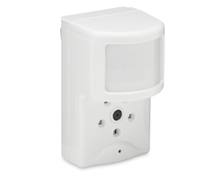
PRODUCT SUMMARY
The Image Sensor is a pet immune PIR (passive infrared) motion detector with a built-in
camera. The sensor is designed to capture images during alarm or non-alarm events.
Users can also initiate image capture on-demand to Peek-In on their property. Images are
stored locally and uploaded either automatically when motion is captured during alarm
events or manually when requested by the user. Once uploaded, images are available for
viewing on the Alarm.com Website or an Alarm.com Smart phone app. The sensor is
battery powered, all wireless and simple to install and operate. A system with a 2GIG Cell
Radio Module connected to an Alarm.com account with service plan subscription is
required. For additional information on product features, functionality and service plan
options, visit the Alarm.com Dealer Site (www.alarm.com/dealer).
Highlighted Features
Battery operated
Communicates wirelessly to the security control panel
35 feet by 40 feet detection coverage area
Configurable PIR sensitivity and pet immunity settings
Image: QVGA 320x240 pixels
Color Images (except in night vision)
Night vision image capture with infrared flash (black & white)
Tamper detection, walk test mode, supervision
HARDWARE COMPATIBILITY & REQUIREMENTS
Security Control Panel: 2GIG Go!Control with software 1.10 & up
Communication Module: 2GIG Cell Radio Module
Required Radio: 2GIG-XCVR2-345
Available Zones: One zone per Image Sensor installed (Up to 3 Image Sensors per
system)
HARDWARE INSTALLATION
IMPORTANT: For smoothest installation, learn in one Image Sensor at a time. Insert
batteries only after initiating learn mode at the panel. (See 4-f)
1. Create Alarm.com Customer Account- Using the 2GIG Cell Radio Module serial
number, create an Alarm.com customer account on the Alarm.com Dealer Site
(www.alarm.com/dealer) with an Image Sensor capable service plan.
2. Verify module & XCVR2 radio installation- Ensure that the communication module
and XCVR2 radio are connected and installed properly inside the control panel.
3. Register Module and Test- Power up the panel and initiate a cell phone test to ensure
the communication module is properly installed and communicating with Alarm.com.
4. Enroll Sensor in Panel-
a. Enter the “system configuration” menu in the “installer toolbox”.
b. Under Q1, select the RF sensor #. (Unused zone 01 to 48)
c. Select the RF sensor type. (Recommended: 04- Interior Follower, 10-
Interior w/ Delay, 23- No Response Type)
d. Select RF sensor equipment type. ((2) Motion)
e. Select RF sensor equipment code. (9999 ADC Image Sensor)
f. Register the RF Sensor Serial Number. Click “learn” to initiate learn
mode on the panel and XCVR2 radio. Power up the Image Sensor by
inserting the batteries or using a paper clip to hold the sensor’s reset
button for 3 seconds.
g. Select RF sensor equipment age.
h. Select RF sensor loop number. (Recommended: Loop 1)
i. Select RF sensor dialer delay.
j. Construct RF sensor voice descriptor. (Recommended shortcuts: 147-
Motion Detector, 120- IS)
k. Select RF sensor reports. (Recommended: (1) Enabled)
l. Select RF sensor supervised. (Recommended: (1) Enabled)
m. Select RF sensor chime.
n. Continue to edit next sensor or select skip, end and exit to save
changes.
o. Perform a cell phone test to ensure that the updated equipment list is
sent to Alarm.com.
The sensor is now learned into the panel. After enrollment, be sure to keep the sensor
and panel powered so the sensor can complete an initialization process with the
Alarm.com Network Operations Center. This process will take several minutes. Images
cannot be captured until initialization is complete. To verify that this process is
complete, enter the “Image Sensors” menu in the “installer toolbox”. Select the Image
Sensor of interest and verify “rules status: complete”.
5. Choose Sensor Location and Mount
a. Determine sensor mounting location based on installation scenario and criteria
noted in the “Installation Guidelines.” For best image capture, the target capture
areas should be centered in the frame. (e.g. If customer wants to capture people
coming through door, the doorway should be centered in camera/PIR view.)
b. Verify RF communication prior to mounting- To verify that the Image Sensor
communicates with the control panel in its mounting location, enter “system test”
through the “installer toolbox” and trigger the Image Sensor.
c. Determine desired mounting angle for customer scenario; attach mounting arm to
sensor-back and re-attach sensor to sensor-back. The mounting arm attaches to the
back of the sensor enabling the sensor angle to vary based on the application. To
obtain the full 35’ x 40’ coverage area, mount the sensor at a 6˚
downward angle. This corresponds to a “teeth up” orientation of the mounting arm.
For most smaller areas in residential installations, mount the arm with the “teeth
down” for a deeper angle (18˚). Secure the back of the sensor to the mounting arm
with the provided screw. If the camera will be mounted perpendicular to the wall, the
mount the sensor without the mounting arm/bracket directly on the wall, at a 12°
angle.
Mounting Arm Orientation Attach Mounting Arm to Sensor-Back Attach Sensor to
(Top: Teeth Up, Bottom: Teeth Down) Sensor-Back
d. Choose applicable mounting bracket for customer scenario. The sensor
hardware packet contains 2 mounting brackets for different mounting scenarios.
Use the provided large screws and anchors to attach the bracket to the wall.
Flat Wall Mount Corner Wall Mount
Mark location of bracket holes on mounting surface at a height of 8 feet for maximum
coverage area. (Leave at least 3 inches of clearance above the sensor to allow for
battery replacement without uninstalling the mounting bracket.)
e. Place sensor with arm on mounting bracket. Adjust the horizontal positioning of
the sensor to point towards the desired coverage area. To adjust positioning, lift the
mounting arm at least 1/3 of the way off the bracket and rotate the arm.
f. Secure the mounting arm location by sliding lock pin into the hole. Use the washer
and remaining small screw to secure the lock pin by screwing upwards through the
bottom of the hole in the mounting bracket. (Note: To make it easier to adjust
PIR/camera field of view in step 10, complete this step after horizontal sensor
positioning is finalized.)
6. Complete PIR Testing
Verify that PIR coverage adequately covers area by performing a walk test. (See “Pro-
gramming” section for more details.)
7. Test Image Capture
To conserve the customer’s monthly image upload quota, automatic alarm uploads are
disabled for the first four hours after any new sensor (Image Sensor or other) is installed
into the system. Installers can verify sensor positioning and test image captures on
installed sensors on Alarm.com’s Mobile Tech website (www.alarm.com/MobileTech)
without accessing the customer’s account or deducting from the customer’s monthly
upload quota. If possible, installers should also test night vision captures to ensure
sensor infrared flash is not reflecting off surfaces and washing out images.
Alarm.com Image Sensor Installation Guide
2 Copyright © 2012 Alarm.com. All rights reserved. Rev 1.0
To access the Mobile Tech website, go to www.alarm.com/MobileTech and login with an
Alarm.com Dealer website login name and password. Select the customer’s account
and navigate to the “Image Sensor” section. Images are requested and viewed through
the “Image Testing” tab. For privacy reasons, a local comm. test must be performed
prior to requesting an image through Mobile Tech.
(Note: If the installer needs to continue testing beyond the 4 hour window, disable alarm
auto-uploads first from the Alarm.com Dealer or Mobile Tech website or the image
uploads will be deducted from the customer’s monthly quota.)
PIR Lens and Camera Coverage Diagrams
Figure 1.Side View: PIR Lens Coverage
Figure 2.Top View: PIR Lens Coverage
As indicated in Figure 2, the camera coverage area is narrower than the PIR coverage
area. When installing, mount sensor where subjects are likely to be centered in or across
PIR and camera field of view.
INSTALLATION GUIDELINES
Before permanently mounting the Image Sensor, evaluate potential locations and consider
the following factors to ensure optimal performance and false alarm protection:
Range- Is the location close enough to the security panel to ensure adequate signal
strength?
False Alarm Immunity- Is installation location false alarm prone? Reduce the risk of
motion-triggered false alarms by making sure the location is free of vibration and the
device does not face a local heat source, window, or areas with high pet activity. (Also,
make sure area is free of elevated surfaces where pets may climb.)
Capture Orientation- Is the location ideally suited for detecting motion and capturing
images when there is an intruder or activity? Consider where the subject is likely to enter
the area and whether or not they will be facing the sensor.
Lighting Conditions- How good is the artificial and natural light? Will daytime and
nighttime lighting conditions ensure adequate image quality?
If possible, locate sensor within 100 ft of the panel especially if there are many walls
between the sensor & panel, or if the panel and sensor are located on different floors.
Avoid facing the sensor toward or close to areas that may affect communication such
as metallic objects or electronics likely to produce interference. Verify sensor RF
communication at panel, even if within recommended distance.
For optimal detection capabilities, mount the sensor where someone will most likely
walk across the sensor coverage area as opposed to directly towards the sensor.
By default, the Image Sensor is set to “Normal” sensitivity. A more sensitive motion
profile (“High”) and a less sensitive profile providing pet immunity for pets up to 40 lbs
(“Low”) can be selected at the control panel or through the Alarm.com Dealer Website.
The Image Sensor is designed for indoor use only and should not be installed outdoors.
For proper operation in pet immune applications, the room should be kept between 60°
and 110° F.
To maximize night vision image quality, do not orient sensor towards surfaces that will
create glare when infrared flash occurs. Avoid orienting the sensor such that the ceiling
or adjacent walls are in the camera field of view.
Mount the sensor on a flat wall surface (do not set on shelf) free of vibrations.
PROGRAMMING
The Image Sensor is enrolled into the control panel via the “system configuration”.
Additional programming options available for configuring and testing include:
A. PIR Sensitivity Settings
By default, the Image Sensor is configured with a standard motion sensitivity profile
(“Normal”). The sensor can also be set to a more sensitive motion profile (“High”) and a
less sensitive profile with pet immunity for pets up to 40 lbs (“Low”). The sensitivity can be
configured through the control panel or Alarm.com Dealer Website.
From the panel, access the “image sensors” menu in the “installer toolbox”. Select the
senor you want to configure and choose the new sensitivity level.
(Note: Using the high sensitivity profile increases the risk of false alarms, especially if the
sensor is facing windows or sources of heat. When mounting the sensor near windows or
heat sources use caution and select the “Low” PIR sensitivity setting.)
B. PIR Activation and Test Mode
During normal operation, the PIR can be activated at most once every three minutes while
the system is disarmed. There is a 30-second delay after powering before PIR detection is
active. For the first 3 minutes after a sensor is enrolled in a network, the sensor will enter
PIR test mode and the sensor LED illuminates for 3 seconds upon each motion activation
(at most every 8 seconds). For additional testing time, put the sensor into test mode by
tampering it.
C. Tamper and Malfunction Reports
Tamper and malfunction reports are issued at the control panel. If subscribed, the
customer will also receive notifications from Alarm.com.
A built-in accelerometer detects movement or re-positioning of the Image Sensor and will
initiate a tamper whenever a change in sensor orientation is detected. Reporting occurs
even if the sensor back plate remains in place. The tamper automatically clears after the
sensor is returned to the upright position and no movement has been detected for 5
minutes. A tamper can also be cleared by resetting the sensor.
D. Sensor LED
By default, the image sensor LED does not illuminate when activated by motion unless the
sensor is in test mode. The LED can be enabled via the Alarm.com Dealer Website for
each Image Sensor on a customer’s account. When enabled, the LED illuminates for 3
seconds upon motion activations (at most every 3 minutes while disarmed).
E. Image Capture Settings
Capture settings are configured automatically for each sensor based upon the customer’s
Image Sensor service plan so it is important to subscribe the customer to a service plan
before enrolling the sensor into a network.
For more information on the Image Sensor service plan options visit the Alarm.com Dealer
Site (www.alarm.com/dealer).
SENSOR RESET BUTTON
Insert a paperclip into the hole on the front of the sensor to access the reset button. Press
and hold for 3 seconds to power cycle the sensor. Press and hold a full 10 seconds until
the sensor LED flashes rapidly to reset the sensor and clear it from its network. The
sensor must be reset prior to enrolling in a new network.
(Note: The sensor can only be cleared from its network using the reset button if it is
currently not communicating with its network. If the sensor is still communicating with its
network, clear sensor by deleting it from the system it is enrolled in.)
Figure 3.Sensor Reset Button
BATTERY REPLACEMENT
When a sensor‘s batteries are low, the panel will display a low battery alert for the sensor.
Notifications are also issued via the Alarm.com platform if the customer has subscribed to
this notification type.
To replace the sensor batteries, slide the front of the sensor up off the sensor-back. (No
need to remove or un-mount entire sensor-back and mounting arm.) To maximize battery
life, replace the sensor batteries with 2 AA 1.5v Energizer Ultimate Lithium batteries.*
Dispose of used batteries according to the battery manufacturer instructions and following
local regulations.
Alarm.com Image Sensor Installation Guide
3 Copyright © 2012 Alarm.com. All rights reserved. Rev 1.0
Figure 4. Removing Sensor for Battery Replacement
*The operation of the sensor with alkaline batteries has not been verified for
compliance with UL standards.
OTHER FEATURE COMPATIBILITY
Two-Way Voice Compatibility
Images cannot be transmitted while a Two-Way Voice call is in session. When the Image
Sensor is installed on a system with Two-Way Voice over the cellular network, image
transmission during an alarm may be interrupted by the two-way session. Image trans-
mission resumes once the call has terminated.
TS1 Compatibility
The Image Sensor uses the same RF radio (XCVR2) as the 2GIG TS1 touchscreen. Both
the Image Sensor and TS1 may be used on the same system using the same radio.
TROUBLESHOOTING
Sensor Not Enrolling
Verify Sensor is Receiving Power: After inserting batteries, the sensor LED should
illuminate or flash within 10 seconds.
Verify Sensor is Not Communicating with Another Network: If the sensor has been
previously enrolled in a different system, delete the sensor from the system and hold
the sensor reset button for 10 seconds to clear the sensor before attempting to enroll
the sensor in a new network. The sensor cannot be cleared if it is currently
communicating with its network. In this case the sensor must be deleted from the
system first through the control panel or remote command.
Sensor Non-Responsive
Replace Batteries: Check battery level at the panel (under “Image Sensor” in the
“installer toolbox”) and install fresh sensor batteries.
False Motion Activations
Check Environmental Elements: Heating or cooling elements may adversely affect
sensor performance. Test sensor with and without these elements to determine
interference.
Check Sensor Positioning: The sensor may not be properly positioned to capture the
desired motion. Check horizontal positioning of sensor and re-mount as necessary.
Check PIR Sensitivity Setting: Verify that the proper sensor motion profile has been
selected through the setup menu or select a less sensitive profile.
Sensor Tamper
The sensor detects changes in sensor orientation and can register a tamper regardless
of the sensor-back being removed. A tamper automatically clears after the sensor has
been returned to the upright position and has not detected any tamper activity for 5
minutes. With the sensor mounted, the tamper may also be cleared by holding the
sensor reset button for 3 seconds to initiate a power cycle.
Images Not Captured
Check Service Plan: Make sure the account has the proper Image Sensor add-on.
Images cannot be captured without an Image Sensor service plan. For alarm
functionality, add the “Image Sensor Alarms” plan. For alarms and enhanced
functionality, add the “Image Sensor Plus” plan.
Verify Sensor Rules: Make sure the sensor initialization process has been completed.
On the Dealer Website, make sure that the sensor rules have been confirmed using the
“Rules Confirmed” column.
Enable Auto Uploads: During the first four hours after any sensor is enrolled onto the
system, alarm images are not automatically uploaded to Alarm.com. Automatic
uploads are automatically enabled after four hours. Enable uploads sooner from the
Dealer Website. On the Image Sensor Plus plan, view and request captured images
from any test alarms from the Customer Website.
If the camera LED is blinking, refer to this chart for LED trouble diagnostics.
Image Sensor Red Status LED Activity Reference
Device Status
or Error
LED
Pattern
Duration of LED Pattern
Sensor Power-
Up
Solid for 5
Seconds
Approximately first 5 seconds after powering.
Sensor Joins or
Rejoins Network
Solid for 5
Seconds
First 5 seconds after sensor joins a new network
(during enroll process) or rejoins its existing
network.
Searching for
Network to Join
Fast Blink
for 5
Seconds at
a Time
Repeats pattern for up to 60 seconds after powering
until the sensor enrolls in a network.
Attempting to
Rejoin Network
Slow Blink
for 5
Seconds at
a Time
Repeats pattern for up to 60 seconds after power
cycle until the sensor reconnects to its network.
(Note: This means the sensor has already been
enrolled into a network and is trying to connect to it.
If attempting to enroll sensor in a new network, hold
reset button for a full 10 seconds (until LED blinks
rapidly) to clear the old network before adding to new
network.)
Motion Test
Mode
Solid for 3
Seconds at
a Time
Repeats for each motion activation during the 3
minutes after sensor joins network, has been
tampered, or is placed in PIR test mode. (Note: In
test mode, there is an 8 second “sleep” timeout
between motion trips.)
Network
Communication
Problem
Fast Blink
for 1
Second at
a Time
Pattern begins after 60 seconds of searching for (and
unsuccessfully joining) a network and repeats until
RF communication is restored. Pattern persists as
long as the sensor is not enrolled in a network or
cannot connect to current network.
TECHNICAL SPECIFICATIONS
Alarm.com Model Number: ADC-IS-100-GC
2GIG Part Number: 2GIG-IMAGE1
Power Source: 2 AA 1.5v Energizer Ultimate Lithium Batteries
Expected Battery Life: Approximately 1 year. Battery life varies by use case depending
on certain factors such as frequency of motion activations, image captures, and IR flashes.
Voltage Thresholds: Low battery alerts are issued at 3.05V. The sensor cannot operate
when the voltage reads below 2.3V.
Operating Temperature Range: 32° to 110°F for non-pet applications, 60° to 110°F for
pet applications
Weight: 3.1 oz. (with batteries, without mounting accessories)
Dimensions: 3.1’’ h x 1.8’’ w x 2.3’’ d
Supervisory Interval: 1 hour
Color: White
Recommended Mounting Height: 8 ft
Recommended Mounting Angle: 6° for large coverage area and rooms greater than 30 ft
(“teeth up” on mounting arm); 18° for rooms less than 30 ft (“teeth down” on mounting arm)
Motion Profiles & Sensor Range: Normal (up to 30 ft, default), High (up to 35 ft), Low (up
to 25 ft)
Rev 1.0 012313
- Uploaded