2GIG-TS1 Installation Guide
Related Products
Related Categories
Document Transcript
Copyright © 2014 Linear LLC 1
2GIG-TS1-E
WIRELESS TOUCH SCREEN KEYPAD
INSTALL INSTRUCTIONS
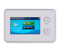
The Wireless Touch Screen Keypad (2GIG‐TS1‐E) is a wall‐mounted,
full‐color, touch screen interface that provides many of the same easy‐
to‐use keypad functions available on the control panel. It is designed
for indoor use only and gives users the ability to control lights,
thermostats, and door locks, as well as to view the status of every
sensor zone.
When the 900 MHz Transceiver Module (2GIG‐XCVR2‐345) is installed
in the control panel, the system can be programmed to communicate
with up to four (4) Wireless Touch Screen Keypads.
NOTE: Wireless Touch Screen Keypads marked with serial
numbers greater than 1405XXXXXXXXXXXX also include a
barrel connector power option (2GIG‐AC2‐PLUG or 2GIG‐AC3‐
INT‐PLG) that makes it easy to connect power to the keypad.
These keypads also include a built‐in, 90‐degree, four (4)‐pin
header for use with the Firmware Update Cable (2GIG‐PCBL2).
IMPORTANT: This keypad does not support UL 985 installations.
Box Contents
Verify that the package includes the following:
• 1—Wireless Touch Screen Keypad
• 1—AC Adapter
• 1—AC Adapter Bracket (with adhesive‐backing)
• 1—Plastic Zip Tie
• 3—Plastic Wall Anchors and Phillips Head Screws
TIP: The box contents will vary depending on whether the keypad
was purchased as part of a kit or not.
Figure 1 Wireless Touchscreen Keypad
TIP: The Secret Duress button does not provide installers with the
ability to access the Installer Toolbox from the keypad. The
Installer Toolbox is only available on the control panel.
Minimum Requirements
For successful communications, the system must meet these
minimum requirements:
• A 900 MHz Transceiver Module (2GIG‐XCVR2‐345) must be
installed in the control panel.
• The Go!Control Panel must be running Version 1.10 or higher.
• The TS1‐E keypad must be running Version 1.10. See Verifying
the Firmware Version on Both Devices on page 4.
Installing the Keypad
Ideally, the keypad should be mounted to a wall at about eye level. In
addition:
• The location must have AC power available and nearby.
• Avoid locations with studs, electrical wires, and/or pipes.
Recommended Tools
The following tools are recommended when mounting the keypad to
the wall:
• #6 Insulated Spade Terminals
• Drywall Saw (or equivalent)
• Ladder
• Pencil
• Screwdriver
• Staple Gun
• Wire (for details, see Determining the Wire Gauge and
Maximum Length on page 2)
• Wire Stripper
Mounting the Keypad to the Wall
To mount the keypad to the wall:
1 Remove the screw from the back cover (see A below).
2 Flip open the back cover (see B below).
Figure 2 Wireless Touch Screen Keypad—Back Cover
3 Remove the plastic hanging strap (see A below) from the inside of
the back cover. You will use the back cover as the mounting plate.
A Emergency Button. Displays Panic, Fire, and Emergency alarm activation
(each has programmable options and can be enabled or disabled).
B Home Button. Changes the screen display to the Home screen.
C Secret Duress Button. Users can press the button while the system is
armed or disarmed and then enter a Duress User Code to send a silent
duress report to the central station. To learn more, see the control panel’s
User Guide.
2 Copyright © 2014 Linear LLC
4 Leave the other end of the plastic strap attached to the circuit
board (see B below).
Figure 3 Wireless Touch Screen Keypad—Remove Hanging Strap
5 Hold the back cover at the desired location on the wall. Then use
pencil to mark the location of the power wire (see A below) and
screw holes (see B below).
Figure 4 Wireless Touch Screen Keypad—Mounting Holes
6 Use a drywall saw to cut an access hole for the power wire. See A
below.
7 Attach the mounting plate to the wall using the screw holes. See B
below.
Figure 5 Wireless Touch Screen Keypad—Mounting Plate
Determining the Wire Gauge and Maximum
Length
To determine the appropriate wire gauge and length to use, measure
the voltage output of the control panel’s power terminals. The
terminals are located on the back of the control panel.
TIP: To avoid the reporting and display of nuisance “AC Power
Loss” messages, the measured voltage must not fall below 14
Volts DC.
Use the table below as a guide for selecting the gauge for the power
wires. To ensure proper operation, do not exceed the following
maximum length for the wire gauge installed:
IMPORTANT: In the United States, wiring routed inside walls,
ceilings, and floors must be in compliance with the
requirements for NFPA 70: National Electric Code and local
building codes. To satisfy these requirements, it is
recommended that the wiring from the AC Power Adapter
output be rated CL2, CL2X, CL2R, or PLTC. When installing
wiring in a plenum space (e.g., a pathway used to facilitate air
circulation for heating and air conditioning systems) the wire
must be plenum‐rated (CL2P).
Connecting the Power Wires to the Keypad
NOTE: If you will be connecting power to the keypad using the
barrel connector power option, you will not need to complete
the steps below. Simply connect the AC Power Supply to the
keypad and power outlet. Then continue with Programming
the Keypad to the Control Panel on page 3.
To connect the power wires to the keypad:
1 Route the wire between the power supply and keypad1.
2 Reconnect the plastic hanging strap to the inside of the back cover.
3 Use #6 Insulated Spade Terminals (not provided) to connect the
power wires to the keypad. The connections are polarity sensitive.
Always observe the (+) and (‐) markings on the unit.
Figure 6 Wireless Touch Screen Keypad—Connecting Power Wires
4 Align and snap the back cover closed. See A below.
Wire Gauge Maximum Length
22 AWG 55 feet (16.8 meters)
20 AWG 85 feet (25.9 meters)
22 AWG 2‐pairs (19 AWG equivalent) 110 feet (33.5 meters)
18 AWG 135 feet (41.1 meters)
Copyright © 2014 Linear LLC 3
5 Reattach the screw to the back cover. See B below.
Figure 7 Wireless Touch Screen Keypad—Close Back Cover
6 Connect the other side of the power wiring to the AC Adapter
(provided). The connections are polarity sensitive. Always observe
the (+) and (‐) markings as follows:
• Left Terminal 14 VDC (+). See A below.
• Right Terminal 14 VDC (‐). See B below.
Figure 8 AC Adapter
NOTE: The power wire (see C above) goes to the keypad.
Programming the Keypad to the Control Panel
To communicate with up to four (4) Wireless Touch Screen Keypads,
you must install the 900 MHz Transceiver Module (2GIG‐XCVR2‐345)
in the control panel before using the programming steps below.
To program the keypad into the control panel:
1 Connect the AC Adapter to the keypad as described in Connecting
the Power Wires to the Keypad.
2 Power ON the keypad. The This Device is Not Paired with a
Control Panel message appears on the keypad’s screen.
3 Ensure the control panel is powered ON. Then tap the Home
button.
4 Tap the logo in the lower‐right corner of the control panel Home
screen.
5 At the Enter Your Code screen, enter your four (4)‐digit installer
code.
6 At the Installer Toolbox (page 1 of 2) screen, tap System
Configuration.
7 At the Q1: Select RF Sensor # (01 to 48) screen, tap Go To.
8 At the Enter Question Number (2 Digits) screen, enter 04
9 At the Q4: Select RF Keypad # (1 to 4) screen, tap → to scroll to
the desired keypad number (1‐4). For example, tap → to scroll to
(1) keypad one. Then tap ↓.
10 At the Q: Select RF Keypad # Used (0 to 1) screen, tap → to scroll
to (1) Enabled. Then tap ↓.
11 At the Q: Select RF Keypad # Equipment Code screen, tap → to
scroll to (1059) 2GIG‐TS1 Wireless Touch Screen Keypad. Then tap
↓.
12 At the Q: RF Keypad # Keypad ID (Read‐Only) screen, press the
Learn button. This places the control panel into learning mode.
13 On the control panel at the Pair with Xcvr Device screen, the
“initiating learning process” message appears.
14 On the keypad, at the This Device is Not Paired with the Control
Panel screen, tap Pair with Panel. This places the keypad into
learning mode.
When the “learn operation succeeded” message appears on both
the control panel and keypad, the devices are linked.
15 Ensure the following is true:
• On the control panel at the Pair with Xcvr Device screen,
ensure the Type reads 2GIG‐TS1‐E Wireless Touch Screen
Keypad and that the ID# appears. Tap OK.
• On the keypad at the Pair with Panel screen, ensure that the
Network ID shows a unique hexadecimal number for the
control panel and that the Keypad ID number appears. Tap OK.
16 On the control panel at the Pair with Xcvr Device screen, tap OK.
Then tap ↓.
NOTE: The keypad displays a “The Security System is Temporarily
Not Operational” message and remains in this state until you
finish programming the device into the panel, save the
changes, and exit out of programming mode.
17 At the Q: RF Keypad # Keypad ID (Read‐Only) screen, ensure the
keypad ID appears. Then tap ↓.
18 At the Q: Select RF Sensor # Equipment Age screen, tap → to
select one of the following:
• (0) New (Default). Then tap ↓.
OR
• (1) Existing. Then tap ↓.
19 At the Q: Construct RF Sensor # Voice Descriptor screen, the voice
descriptor keypad one (or keypad two, keypad three, and so on.)
should display.
If you want to change the voice descriptor, tap the delete (X)
button. Then tap Insert. Then enter the appropriate voice
descriptor code. For example, to create a voice descriptor code
named keypad one, do the following:
• Tap Insert. Then enter 123 for keypad.
• Tap Insert. Then enter 161 for one. Then tap ↓.
TIP: For a complete list of available voice descriptors, see the
control panel’s Quick Programming Guide.
20 At the Summary of RF Keypad # screen, tap Skip.
21 At the Q5: Enter Exit Delay, in Seconds (45‐120) screen, enter the
desired exit delay. The default value is 60. The tap End. This setting
affects both the control panel and keypad.
22 At the Summary of System Configuration screen, tap Save
Changes and ensure a checkmark appears in the Save Changes
box. Then tap Exit. This restarts the control panel.
NOTE: You can program up to four (4) keypads into the control
panel by repeating the steps above.
4 Copyright © 2014 Linear LLC
Disabling a Keypad from the Control Panel
If you want to disable a keypad after programming it into the control
panel:
1 Ensure the control panel is powered ON. Then tap the Home
button.
2 Tap the logo in the lower‐right corner of the control panel Home
screen.
3 At the Enter Your Code screen, enter your four (4)‐digit installer
code to go to the Installer Toolbox (page 1 of 2) screen.
4 At the Installer Toolbox (1 of 2) screen, tap System Configuration.
5 At the Q1: Select RF Sensor # (01 to 48) screen, tap Go To.
6 At the Enter Question Number (2 Digits) screen, enter 04.
7 At the Q4: Select RF Keypad # (1 to 4) screen, tap → to scroll to
the keypad number (1‐4) to remove. For example, tap → to scroll
to (1) keypad one. Then tap ↓.
8 At the Q: Select RF Keypad # Used screen, tap → to scroll to (0)
Disabled. Then tap ↓.
9 Tap ↓ unl the Summary of RF Keypad # screen appears. Then
tap Skip.
10 At the Q5: Enter Exit Delay, in Seconds (45‐120) screen, tap End.
11 At the Summary of System Configuration screen, tap Save Changes
and ensure a checkmark appears in the Save Changes box. Then
tap Exit. This restarts the control panel.
Restoring the Keypad’s Factory Settings
To restore the keypad’s factory settings to use it with a different
control panel:
1 Power OFF and then power ON the keypad.
2 Press and hold down both the Emergency and Home
buttons for approximately 20 seconds.
3 When both buttons illuminate, the keypad’s factory settings have
been restored. The screen will display the following message:
“This Device is Not Paired with a Control Panel.”
Verifying the Firmware Version on Both Devices
In order to communicate properly, the keypad and the control panel
must be running the same firmware version.
NOTE: If the keypad has not yet been paired to the control panel,
the firmware version number displays on the keypad’s main
screen.
To check the firmware version on the keypad and control panel (after
they have been paired):
1 Press the Home button.
2 At the Home screen, tap Security.
3 Tap Menu.
4 Tap Toolbox.
5 At the Enter Your Code to Access the Toolbox screen, enter the
master code.
6 At the Toolbox (1 of 3) screen, tap → to scroll to the Toolbox (2 of
3) screen.
7 Tap Version.
8 At the Version screen, ensure the Firmware Version field matches
on both the control panel and keypad.
Updating the Firmware
To update the firmware on the keypad, you will need:
• The Firmware Update Cable for the TS1 and Control Panel
(2GIG‐UPCBL2).
• To download the latest firmware update go to dealer.2gig.com.
For instructions, refer to the document titled Update the Firmware on
the Control Panel and TS1 (PN: 77‐000001‐001).
SPECIFICATIONS
REGULATORY INFORMATION
Wireless Product Notice
Radio controls provide a reliable communications link and fill an
important need in portable wireless signaling; however, there are
some limitations which must be observed.
• For United States Installations Only: The radios are required to
comply with FCC Rules and Regulations as Part 15 devices. As such,
they have limited transmitter power and therefore limited range
(approximately 400 ft.).
• A receiver cannot respond to more than one transmitted signal at
a time and may be blocked by radio signals that occur on or near
their operating frequencies, regardless of code settings.
• Changes or modifications to the device may void FCC compliance.
• Infrequently used radio links should be tested regularly to protect
against undetected interference or fault.
• A general knowledge of radio and its vagaries should be gained
prior to acting as a wholesale distributor or dealer, and these facts
should be communicated to the end users.
FCC Notice
This device complies with Part 15 of the FCC Rules. Operation is
subject to the following two conditions:
1 This device may not cause harmful interference, and
2 This device must accept any interference received, including
interference that may cause undesired operation.
This equipment has been tested and found to comply with the limits
for Class B Digital Device, pursuant to Part 15 of the FCC Rules. These
limits are designed to provide reasonable protection against harmful
interference in a residential installation. This equipment generates
and can radiate radio frequency energy and, if not installed and used
in accordance with the instructions, may cause harmful interference
to radio communications. However, there is no guarantee that
interference will not occur in a particular installation. If this
equipment does cause harmful interference to radio or television
reception, which can be determined by turning the equipment off and
on, the user is encouraged to try to correct the interference by one or
more of the following measures:
• Reorient or relocate the receiving antenna
• Increase the separation between the equipment and receiver
Wireless Signal Range 500 ft (152.4 m), open air, with Wireless Control Panel
Transceiver Silicon Labs SI1001‐E‐GM2
Transceiver Frequency 900 MHz frequency‐hopping bi‐directional
communication
Radio 25 channel frequency‐hopping spread spectrum, 403
kHz channel spacing (910.2‐920.275 MHz), GFSK
modulation, 128 kbps, +19dBm maximum RF power out
Dimensions (L x W x H) 4.3” x 6.7” x 0.8” (11 x 17 x 2 cm)
Weight (including bat‐
tery)
9.6 oz.
Housing Material ABS Plastic
Color White
Operating Temperature 32°‐120 F° (0°‐49° C)
Relative Humidity 5‐95% Non‐Condensing
Operating Voltage 14VDC
Certification FCC, Industry Canada, IFETEL, and NOM
Copyright © 2014 Linear LLC 5
• Connect the equipment into an outlet on a circuit different from
that to which the receiver is connected
• Consult the dealer or an experienced radio/TV technician for help
Any changes or modifications not expressly approved by the party
responsible for compliance could void the user’s authority to operate
the equipment.
Industry Canada Notices
This device complies with Industry Canada licence‐exempt RSS
standard(s). Operation is subject to the following two conditions: (1)
this device may not cause interference, and (2) this device must accept
any interference, including interference that may cause undesired
operation of the device.
Repairs to certified equipment should be made by an authorized
Canadian maintenance facility designated by the supplier. Any repairs
or alterations made by the user to this equipment, or equipment
malfunctions, may give the telecommunications company cause to
request the user to disconnect the equipment.
Users should ensure for their own protection that the electrical
ground connections of the power utility, telephone lines and internal
metallic water pipe system, if present, are connected together. This
precaution may be particularly important in rural areas.
WARNING: Users should not attempt to make such connections
themselves, but should contact the appropriate electric
inspection authority, or electrician, as appropriate.
Operating and Storage Temperature
The recommended storage temperature for all touchscreens is ‐10°C
to 60°C (14°F to 140°F).
For optimal touchscreen use, operational temperature is 0°C to 49°C
(32°F to 120°F).
LIMITED WARRANTY
This Linear product is warranted against defects in material and
workmanship for one (1) year. This warranty extends only to
wholesale customers who buy direct from Linear LLC or through
Linear LLC’s normal distribution channels. Linear LLC does not warrant
this product to consumers. Consumers should inquire from their
selling dealer as to the nature of the dealer’s warranty, if any.
There are no obligations or liabilities on the part of Linear LLC for
consequential damages arising out of or in connection with use or
performance of this product or other indirect damages with respect to
loss of property, revenue, or profit, or cost of removal, installation, or
reinstallation. All implied warranties for functionality, are valid only
until the warranty expires. This Linear LLC Warranty is in lieu of all
other warranties expressed or implied.
2GIG by Linear
1950 Camino Vida Roble, Suite 150
Carlsbad, CA 92008 USA
For technical support in the USA and Canada:
855‐2GIG‐TECH (855‐244‐4832)
Email: 2gigtechsupport@linearcorp.com
Visit web site for technical support hours of operation
For technical support outside of the USA and Canada:
Contact your regional distributor
Visit dealer.2gig.com for a list of distributors in your region
77‐000090‐001 Rev. E
- Uploaded