ADC-SEM210-PS Dual Path - Install Guide
Related Products

Related Categories
Document Transcript
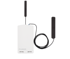
SEM-DSC PowerSeries Dual-Path - Installation Guide
Alarm.com’s Dual-Path System Enhancement Module (SEM) can be used with DSC PowerSeries PC1616, PC1832,
and PC1864 panels to enable wireless reporting of alarms and other system events using the wireless cellular network
and optional Broadband Ethernet. The SEM is intended to be used as the primary communication path for all alarm
signaling to the central monitoring station. The wireless alarm signaling and routing service is operated by Alarm.com.
The SEM also features integrated support for Alarm.com’s home automation services with built-in Z-Wave capabilities.
Tools and supplies needed
•
Small blade screwdriver and Phillips screwdriver
•
Drill and bits for screws and/or wall anchors
•
Four-conductor, 22-gauge or larger stranded wire
•
Alpha keypad
https://answers.alarm.com/Installation_and_Troubleshooting/Panels/SEM-DSC_PowerSeries/SEM-DSC_PowerSeries_Dual-Path_-_Installation_Guide
Updated: Mon, 24 Sep 2018 18:53:30 GMT
1 Alarm.com strongly recommends installing an alpha keypad with at least 32 zones to ensure the “Communication
Failure” trouble condition is displayed to the user. See FAQs on page 16 for more information.
Verify panel compatibility
The SEM is compatible with PowerSeries PC1616, PC1832, and PC1864 firmware version 4.2 or newer.
Create an account
Before installing the SEM, first create a new Alarm.com customer account. We recommend creating the account at least
24 hours prior to installation. This ensures that the SEM is activated prior to installation. To create an account, go to the
Alarm.com Partner Portal or MobileTech and login. The following information is required to create the account:
•
Customer Address
•
Customer Phone Number
•
Customer E-mail
•
Preferred Login Name for the Customer
•
Alarm.com Module Serial Number
•
Existing Panel Installer Code
During the
Create New Customer
process, you are prompted to enter the current installer code on the panel. Alarm.com
uses this code to access panel programming and read information stored on the panel.
https://answers.alarm.com/Installation_and_Troubleshooting/Panels/SEM-DSC_PowerSeries/SEM-DSC_PowerSeries_Dual-Path_-_Installation_Guide
Updated: Mon, 24 Sep 2018 18:53:30 GMT
2 At the end of the
Create New Customer
process, you are
able to print or email a Welcome Letter for the customer, which
includes login information for the Alarm.com Customer Website.
Disconnect power from the panel
Prior to disconnecting power from the panel, first verify that the panel is disarmed.
Next, remove panel AC power and disconnect the backup battery.
https://answers.alarm.com/Installation_and_Troubleshooting/Panels/SEM-DSC_PowerSeries/SEM-DSC_PowerSeries_Dual-Path_-_Installation_Guide
Updated: Mon, 24 Sep 2018 18:53:30 GMT
3 Caution
: This is necessary to prevent damaging the panel or module while making wiring connections.
Mount the SEM
Caution
: You must be free of static electricity before handling electronic components. Touch a grounded metal surface
before touching
the circuit board.
1.
Press down on the bottom tabs of the enclosure cover to remove it and set it aside.
2.
Carefully remove the SEM circuit board by depressing the interior bottom tab.
https://answers.alarm.com/Installation_and_Troubleshooting/Panels/SEM-DSC_PowerSeries/SEM-DSC_PowerSeries_Dual-Path_-_Installation_Guide
Updated: Mon, 24 Sep 2018 18:53:30 GMT
4 3.
Place the SEM back plate on the wall at the desired mounting location and mark the three mounting holes as
shown below.
4.
Set the back plate aside and drill holes at the mounting locations.
5.
Use wall anchors where studs are not present and secure the back plate to the wall with the enclosed screws.
6.
Insert the SEM circuit board back into the back plate.
Wire the SEM to the panel
Caution
: Verify panel AC power is removed and the backup battery is disconnected.
https://answers.alarm.com/Installation_and_Troubleshooting/Panels/SEM-DSC_PowerSeries/SEM-DSC_PowerSeries_Dual-Path_-_Installation_Guide
Updated: Mon, 24 Sep 2018 18:53:30 GMT
5 •
Connect panel terminal SEM GND to BLK.
•
Connect panel terminal YELLOW (IN) to YEL.
•
Connect panel terminal GREEN (OUT) to GRN.
•
Use the included red cable with the two prong battery connector to connect the battery to both the SEM and the
panel. For a power limited circuit, ensure the fuse is inside the PowerSeries panel.
Once wiring is complete, route the antennas
outside of the enclosure, away from the SEM, and replace the enclosure
cover.
Note
: The antennas
should be routed through the second and third channel openings at the top of the enclosure as
shown in the following images:
Dual-Path (Optional)
For Broadband Ethernet, connect the provided Ethernet Dongle to the connector on the SEM.
Connect the Ethernet cable to the provided Ethernet Dongle.
https://answers.alarm.com/Installation_and_Troubleshooting/Panels/SEM-DSC_PowerSeries/SEM-DSC_PowerSeries_Dual-Path_-_Installation_Guide
Updated: Mon, 24 Sep 2018 18:53:30 GMT
6 Power up the panel
Connect the backup battery and restore AC power to the panel. For the SEM to interact with the existing zones on the
system, it must read them from the PowerSeries panel. The SEM does a zone scan
to read this information.
The zone scan automatically begins within one minute after the panel is powered up and should take between 5 and 15
minutes, depending on the number of partitions and zones on the system. Do not touch the panel, keypad, or SEM at
this time.
The zone scan is complete when the green and yellow lights on the keypad remain solid. If you press any buttons on the
keypad during the zone scan, the message
System unavailable
displays on the screen. The date and time shows on the
screen when the zone scan is complete.
Important
: If the system was previously communicating over a phone line, we recommend Disabling Telco Line
Monitoring (Section 15, Option 7) and Removing the Phone Numbers (Section 301-303).
Broadcast sensor names
For the SEM to be able to read the sensor names stored on the panel and display them on Alarm.com, you must
broadcast the sensor names stored on the keypads. This should be done for every install with an LCD keypad and is
necessary even if there is only one keypad on the system.
https://answers.alarm.com/Installation_and_Troubleshooting/Panels/SEM-DSC_PowerSeries/SEM-DSC_PowerSeries_Dual-Path_-_Installation_Guide
Updated: Mon, 24 Sep 2018 18:53:30 GMT
7 Note
: Once broadcasted, sensor names are updated on the Partner Portal and MobileTech. If the sensor names are not
updated, please request the sensor names by selecting
Request Sensor Names
on the Partner Portal or MobileTech.
Add & delete Z-Wave devices
Please visit the Partner Portal Support Center for a complete explanation of Z-Wave communication, Z-Wave signal
strength, and additional installation resources.
Alarm.com does not recognize any Z-Wave devices previously learned into the panel. These devices need to be deleted
from the previous Z-Wave network and added to the SEM for the customer to use Alarm.com’s home automation
services (e.g. automation control via customer website, app, and intelligent automation rules).
Important
: If the customer is on a different interactive platform, we recommend having them log in to that site and taking
screenshots of notifications, rules, and home automation device names for reference later.
Adding Z-Wave devices
Using the Partner Portal or MobileTech is strongly recommended.
Using MobileTech
1.
Move all Z-Wave devices to their final location on the property.
2.
Open MobileTech and select the customer.
3.
Navigate to the Equipment List screen.
4.
Select emPower Management.
5.
Select Add Z-Wave Devices.
6.
Wait for the bolded message: Checking for new devices on the network.
7.
Trigger a device to add it to the network.
8.
When a device is added successfully, it shows up
on this screen following a 30 second delay.
9.
Continue triggering devices. You may add several devices to the network without re-entering Add Mode.
Using the Partner Portal
1.
Move all Z-Wave devices to their final location on the property.
2.
Navigate to the Equipment page on the Partner Portal.
3.
Click the emPower Devices tab.
https://answers.alarm.com/Installation_and_Troubleshooting/Panels/SEM-DSC_PowerSeries/SEM-DSC_PowerSeries_Dual-Path_-_Installation_Guide
Updated: Mon, 24 Sep 2018 18:53:30 GMT
8 4.
Click Add Z-Wave Devices.
5.
Wait for the bolded message: Checking for new devices on the network.
6.
Trigger a device to add it to the network.
7.
When a device is added successfully, it shows up on this screen following a 30 second delay.
8.
Continue triggering devices. You may add several devices to the network without re-entering Add Mode.
Using the SEM
1.
Press and hold Z-Wave button on the Alarm.com module.
2.
Release the button once LED L5 flashes in groups of four. L2 also flashes.
3.
Trigger a device to add it to the network.
4.
When a device is added successfully, L5 illuminates solid.
5.
You need to re-enter Add Mode before triggering the next device.
Note
: If you can’t add a device to the network, you may need to delete the device’s current network data using the
device deletion process before you can add it to the new network (some devices come from the factory with network
data).
Deleting Z-Wave Devices
Using the Partner Portal or MobileTech is strongly recommended.
Using MobileTech
1.
Open MobileTech and select the customer.
2.
Navigate to the Equipment List screen.
3.
Select emPower Management.
4.
Select Delete Z-Wave Devices.
5.
Wait for the bolded message: Checking for deleted devices on the network.
6.
Trigger a device to delete it from the network.
7.
When a device is deleted successfully and its network data is erased, it shows up on this screen following a 30
second delay.
8.
Continue triggering devices. You may delete several devices from the network without re-entering Delete Mode.
Using the Partner Portal
1.
Navigate to the Equipment page.
2.
Click the emPower Devices tab.
3.
Click Delete Z-Wave Devices.
4.
Wait for the bolded message: Checking for deleted devices on the network.
5.
Trigger a device to delete it from the network.
https://answers.alarm.com/Installation_and_Troubleshooting/Panels/SEM-DSC_PowerSeries/SEM-DSC_PowerSeries_Dual-Path_-_Installation_Guide
Updated: Mon, 24 Sep 2018 18:53:30 GMT
9 6.
When a device is deleted successfully and its network data is erased, it shows up on this screen following a 30
second delay.
7.
Continue triggering devices. You may delete several devices from the network without re-entering Delete Mode.
Using the SEM
1.
Press and hold the Z-Wave button on the Alarm.com module.
2.
Release the button once LED L5 flashes in groups of two. L2 also flashes.
3.
Press and hold the Z-Wave button on the module a second time.
4.
Release the Z-Wave button once LED L5 flashes in groups of two.
5.
Trigger a device to erase its network data and delete it from the network.
6.
When a device is deleted successfully, L5 illuminates solid.
7.
You need to re-enter Delete Mode before triggering the next device.
LEDs
The Alarm.com Module LEDs can be used to indicate communication errors, panel communication, network
communication, and signal strength.
LED function
L1 Error LED
L1 flashes 1 to 8 times in a four-second interval to
indicate specific error conditions such as a network
error, panel communication error, or radio error.
L2 Panel communication LED
L2 flashes every time a data packet is received from the
panel.
L3 Cellular communication LED
L3 flashes every time a data packet is received from the
cellular radio.
L4 Cellular signal level LED
L4 flashes 0 to 5 times indicating the cellular signal
strength, or toggles on/of f when communicating with the
Alarm.com servers.
https://answers.alarm.com/Installation_and_Troubleshooting/Panels/SEM-DSC_PowerSeries/SEM-DSC_PowerSeries_Dual-Path_-_Installation_Guide
Updated: Mon, 24 Sep 2018 18:53:30 GMT
10 L5 Z-Wave Error LED
Visit the Partner Portal Support Resources for additional
Z-Wave installation resources.
L6
Reserved for future use.
L7
Reserved for future use.
LED L1 (Red)
L1 flashes when an error is encountered. The number of flashes indicates the error number. If there are two or more
errors at the same time, the errors flashes one after the other. The LED stays off for at least four seconds between
errors.
LED L1 error descriptions and solutions
Number of flashes
Description
1
Alarm.com module cannot communicate with the panel.
Perform a power cycle on the panel. If the error persists
lift the Alarm.com module out of the SEM circuit board
and re-insert it, while power is disconnected from the
system.
2 then 4
The Alarm.com module provisioning process could not
be completed. If the error persists, power cycle the
system, then contact Technical Support.
2 then 5
The Alarm.com module provisioning process could not
be completed because the module is currently roaming
off the carrier’s primary network.
3
The Alarm.com module is trying to register on the
cellular network. If it persists for more than a few
minutes, the module is having problems registering.
Check L4 for signal level. If signal level is lower than 2
bars, change the panel’s location or use a remote
antenna option.
4
The Alarm.com module is registered on the cellular
network but could not connect with Alarm.com. Contact
Alarm.com Technical Support.
5
The radio on the module is not working correctly. If this
persists for more than a few minutes the module may
need to be replaced. This error is extremely rare, so
please verify that the module is flashing 5 times.
https://answers.alarm.com/Installation_and_Troubleshooting/Panels/SEM-DSC_PowerSeries/SEM-DSC_PowerSeries_Dual-Path_-_Installation_Guide
Updated: Mon, 24 Sep 2018 18:53:30 GMT
11 Number of flashes
Description
6
This indicates an error only if it persists for more than a
minute. Otherwise, it’s an indication that the module is
resolving an unusual condition regarding communication
with the cellular network.
7
The SEM is unable to access panel programming.
Check panel wiring and Installer Code.
8
If this error persists, the account may have been set up
incorrectly. Check that the serial number being used
matches the serial number used to create the account. If
the serial numbers are the same, contact Technical
Support.
LED L2 (Yellow)
L2 flashes with every communication between the SEM and the panel. The normal pattern calls for a series of quick
flashes every two seconds when the Alarm.com module is in Idle mode or four seconds in PowerSave mode. See
Alarm.com Module States (modes) for an explanation of the three modes.
L2 also occasionally flashes in patterns to indicate Z-Wave status, when the SEM is being used to add or remove Z-
Wave devices.
LED L3 (Green or Yellow)
L3 flashes with every communication between the SEM and its radio unit in Idle mode, and with every communication
with Alarm.com in Connected mode. In PowerSave mode, this LED flashes in unison with LED L2.
LED L4 (Green or Yellow)
L4 indicates the cellular signal level as a number of flashes (0 to 5 bars). The number of bars may not correspond to the
number of bars shown on your cell phone. A level of 5 bars is obtained only in the strongest signal conditions. Signal
level is updated every ten seconds if it fluctuates,
or every 30 seconds if it is fairly stable.
If LED L4 is continuously flashing, the module provisioning process is in progress. LED L4
begins flashing to indicate
signal level as soon as the provisioning process is complete.
If LED L4 is not flashing, this means one of the following:
•
The Alarm.com module is in PowerSave mode
•
The Alarm.com module just powered up
•
There is no cellular coverage in the area
https://answers.alarm.com/Installation_and_Troubleshooting/Panels/SEM-DSC_PowerSeries/SEM-DSC_PowerSeries_Dual-Path_-_Installation_Guide
Updated: Mon, 24 Sep 2018 18:53:30 GMT
12 In Connected mode, LED L4 toggles on and off.
Important
: Alarm.com recommends a steady signal level of two or higher for proper operation of the SEM.
LED L5 (Yellow)
L5 indicates Z-Wave errors. If you can’t add a device to the network, try deleting the device and re-adding it to the
network. Contact Alarm.com Technical Support with additional issues.
Alarm.com module states (modes)
There are three Alarm.com module states (modes).
Idle Mode
In Idle mode, the AC power is up, the battery level is greater than 11.5 volts, and the SEM is not currently connected to
the Alarm.com servers. This is normal for the SEM and is the most common state.
L1
Flashes errors, if any
L2
Communication with panel
L3
Communication with radio unit
L4
Signal level (0 to 5 bars)
L5
Flashes errors, if any
PowerSave Mode
In PowerSave mode, the module just powered up, AC power is down, or battery level is less than 11.5 volts. The radio
part of the SEM draws 10 mA in PowerSave mode. It is fully functional and goes into Connected mode as soon as a
signal needs to be sent. Performing an Alarm.com phone test switches the module into Idle mode and update the signal
level reading.
L1
Inactive
L2
Communication with panel
L3
Same flashing pattern as L2
L4
Inactive
L5
Inactive
https://answers.alarm.com/Installation_and_Troubleshooting/Panels/SEM-DSC_PowerSeries/SEM-DSC_PowerSeries_Dual-Path_-_Installation_Guide
Updated: Mon, 24 Sep 2018 18:53:30 GMT
13 Connected Mode
In Connected mode, the SEM is connected to the Alarm.com servers and reported an alarm or other condition. The
module stays in Connected mode for at least six minutes after the last message is exchanged. Entering Installer
programming causes the SEM to go into Idle mode.
L1
Flashes errors, if any
L2
Communication with panel
L3
Communication with Alarm.com
L4
Alternates two seconds on, then two seconds off
L5
Inactive
Frequently asked questions
Is the customer notified if the panel fails to communicate with Alarm.com?
Yes. The SEM automatically uses the last available zone on the panel to display this information. The zone is named
Communication Failure
and is displayed on the keypad as if it were an open zone.
Important
: There needs to be one available keypad slot for the SEM and a keypad should never be enrolled in the
same slot as the SEM. The SEM uses the highest available slot at install.
How should I choose the best location to install the SEM?
•
Check the signal strength before choosing a final location. Perform a walking signal strength test by powering the
SEM using the battery directly (connect the GND and +12V terminals). After two minutes, cellular signal level LED
L4 flashes between one and five times to indicate the signal strength (where five is the strongest signal). Alarm.com
recommends a signal level of two or higher for proper operation of the SEM.
•
Avoid mounting the SEM in areas with excessive metal or electrical wiring, such as furnace or utility rooms.
•
Mount the module near an outside wall, preferably on an upper level.
•
Do not mount the SEM inside of the panel’s metal box. Doing so negatively impacts Z-Wave performance.
•
For homes or businesses located in canyons or with hills nearby, it may be necessary to place the antenna higher in
the building.
•
If the SEM location requires a longer power cable, splice the provided power wire with the fuse to your wire and
leave the fuse inside the PowerSeries panel enclosure.
Why do I need to enter the Installer Code during account creation?
The installer code entered during account creation is used to access and read the zones currently learned into the
panel. The installer code can be changed after the zone scan is complete. For more information about account creation,
see
Create an account
.
https://answers.alarm.com/Installation_and_Troubleshooting/Panels/SEM-DSC_PowerSeries/SEM-DSC_PowerSeries_Dual-Path_-_Installation_Guide
Updated: Mon, 24 Sep 2018 18:53:30 GMT
14 How do I initiate or test communication between the SEM and Alarm.com?
Perform an Alarm.com phone test by pressing
[#]
+
[9]
+
[8]
+
[7]
+
[*]
. This phone test is not viewable on the keypad,
but can be verified on the Partner Portal or MobileTech Event History.
How do I get the SEM and Alarm.com to read the sensor names already assigned on the panel?
For the SEM to be able to read the sensor names stored on the panel and display them on Alarm.com, you must
broadcast the sensor names stored on the keypads. For more information, see
Broadcast sensor names
.
Does the SEM support 6-digit user codes?
The SEM does not support 6-digit user codes.
Does the SEM support multiple partitions?
Yes. The SEM comes with multiple partition support, including the ability to arm and disarm partitions using the Mobile
App or Customer Website. Sensors must be enrolled and given partition access on the panel before partitions are
displayed on the Partner Portal, MobileTech, Customer Website or Mobile App.
Can zones be enrolled in multiple partitions?
Zones should only be enrolled in a singe partition. Zones in multiple partitions are not supported by the SEM.
Is the SEM compatible with DLS?
DLS is not supported. The SEM cannot be used as a DLS communicator. DLS panel programming changes via another
communication pathway (PC Link, POTS, etc.) is not captured by the SEM until the system is power cycled.
Do I need to change any programming settings for the SEM to work?
No. There aren’t any required settings that need to be changed. However, we do recommend changing the following
settings if the system was previously communicating over the phone line.
•
Disable Telco Line Monitoring (section 15, option 7)
•
Remove the phone numbers (section 301-303)
Does the SEM support reporting multiple alarms on a single zone (swinger shutdown)?
The SEM only reports one instance of each alarm per alarm event regardless of the settings specified on the panel. The
SEM does not
support reporting multiple alarms on a single zone.
https://answers.alarm.com/Installation_and_Troubleshooting/Panels/SEM-DSC_PowerSeries/SEM-DSC_PowerSeries_Dual-Path_-_Installation_Guide
Updated: Mon, 24 Sep 2018 18:53:30 GMT
15 Can I can add and delete sensors remotely?
Yes. Sensors can be added, changed, or deleted using MobileTech or the Partner Portal.
Are the additional terminals on the SEM circuit board used or needed for the install?
No. These terminals are for future development. Please disregard the relay, zone, ring and tip terminals on the SEM
circuit board.
Does the SEM support Cross Zones?
No. The SEM does not support the Cross Zone attribute. The SEM does not report the Cross Zone event to the
monitoring station.
Are both communication pathways (cellular and Broadband) required?
We recommend using both the cellular and Broadband connection.
However, the SEM communicates with only one signaling path.
Troubleshooting
The equipment
list is empty on the Partner Portal or MobileTech
If the
Equipment List
is not showing on the Partner Portal or MobileTech and the SEM failed to do a zone scan when
initially powered on, verify that:
•
All wiring is correct
•
The Installer Code is synced (if the Installer Code is out of sync you can change it to a new, unique code locally at
the panel)
•
The panel is disarmed, and Request an Equipment List on the Partner Portal or power cycle the panel
None of the LEDs on the SEM are ON
Remove power from the panel and verify that all wiring is correct.
My keypad occasionally displays
System Unavailable
The keypad may display
System Unavailable
for brief moments while interacting with the SEM. This is normal and
expected behavior.
Specifications
Compatibility
DSC PowerSeries PC1616, PC1832, and PC1864
version 4.2 or newer.
https://answers.alarm.com/Installation_and_Troubleshooting/Panels/SEM-DSC_PowerSeries/SEM-DSC_PowerSeries_Dual-Path_-_Installation_Guide
Updated: Mon, 24 Sep 2018 18:53:30 GMT
16 Power Requirements
12 V nominal, 130 mA (continuous) 2000 mA
(instantaneous peaks) maximum (from panel battery)
Cellular Network
Dual Band CDMA (3G), Dual Band HSPA (3G), or Dual
Band 4G LTE
Panel Interfaces
Three keypad bus connections
12V power and ground to panel battery
Alarm.com Module Indicators
One module/panel communication status LED, one
module power LED, one automation LED, three wireless
communication status LEDs
SEM Circuit Board Indicators
One LAN LED, one processor LED, one COMM fail LED
Operating Temperature
32 to 120°F (0 to 49°C)
Storage Temperature
-30 to 140°F (-34 to 60°C)
Humidity
90% relative humidity non-condensing
Enclosure Dimensions
(L x W x D) 7.5 x 4.25 x 1.5 in. (19.05 x 11.43 x 3.81 cm)
Enclosure Color
White
Case Material
High-impact, ABS plastic
Listings
FCC part 15, Verizon Certified
Additional resources
Enroll in the
System Enhancement Module (SEM) 201 - PowerSeries
course today! For more information on
accessing Academy Training, see
How can I access the Training Center on the Partner Portal?
.
https://answers.alarm.com/Installation_and_Troubleshooting/Panels/SEM-DSC_PowerSeries/SEM-DSC_PowerSeries_Dual-Path_-_Installation_Guide
Updated: Mon, 24 Sep 2018 18:53:30 GMT
17
- Uploaded