Alarm.com ADC-T40K-HD - Smart Thermostat w/Color Touchscreen - Install Guide
Related Products
Related Categories
- Programmable Thermostats
- Home Automation Modules
- Thermostats
- Thermostats
- Programmable Thermostats
- Home Automation Modules
Document Transcript
Smart Thermostat HD
Installation Guide
ADC-T40K-HD 1
Installation precautions
• Before installing the Smart Thermostat HD or servicing
the HVAC equipment, turn off power to the system.
• Leave power off until you have finished installing or
servicing the HVAC equipment.
• Shorting the electric terminals at the control on the
heating or cooling system is not recommended.
Do not test the system this way.
• When testing the existing system or the new Smart
Thermostat HD do not run the cooling system when it
is cold outside as this may harm the compressor.
Please wait for mild temperatures before testing the
cooling system.
• You must follow all local codes and ordinances for
wiring the system.
• The Smart Thermostat HD should only be powered
by a listed Class 2 power supply at 24 VAC
(C-wire or wall transformer).
• A current higher than 1 amp to each thermostat
terminal may cause damage to the thermostat.
• Verify that the system is 24 VAC. If the old system is
labeled as 120 V or 240 V or has wire nuts, the system
is high voltage. Do NOT install this thermostat on a
high voltage system. Contact a local HVAC
professional for help.
Questions?
Visit
answers.alarm.com
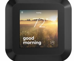
or contact your service provider. Overview
Thermostat
❶
Status LED
❷
Button
Display
❸
Settings menu
❹
Current setpoint
To change the setpoint,
tap on the up or down arrow.
❺
Indoor temperature
❻
Current mode
To change the mode,
tap on the current mode icon
.
In the box
❶
Trim plate
❷
Thermostat
❸
Display
❹
Drywall anchors x2
❺
Wall screws x2
Recommended
tools
❶
Phillips screwdriver
❷
Pencil to mark mounting location
❸
Power drill – 3/16" (#13) drill bit
❹
Needle nose pliers
❺
Camera
2
3
❶
❷
❸
❹
❺
❶
❷
❸
❹
❺
❷
❶
❺
❻
❹
❸ 4
5
Installation considerations
• The Smart Thermostat HD requires 24 VAC power.
There is no option for a battery-powered mode.
Power is supplied via a common wire, typically
identified as C.
Location
• If replacing an existing thermostat, the new
Smart Thermostat HD can be mounted in its place.
If a new location is desired it will be necessary
to move the wiring.
• New installations and relocations should follow the
accompanying guidelines to ensure the most accurate
temperature reading and ease of use.
• Mount on an inside wall, approximately 5 ft. (1.5 m)
above the floor in a frequently used room.
• Do not install in locations near appliances or devices
that affect the local temperature such as televisions,
lamps, or dryers.
• Avoid areas that are exposed to large temperature
variances, such as: direct sunlight, near an AC unit,
above or below auxiliary heat and air vents, and drafts
from windows or exterior doors.
• Be aware of what is on the other side of the wall where
the installation is occurring. Do not install on walls
adjacent to unheated rooms, stoves, or housing hot
water pipes. Exterior walls are also not ideal locations
for installation.
• Damp areas will not only affect the humidity reading
but could lead to corrosion and shorten the lifespan
of the thermostat.
• Install in a location with good air circulation.
Stagnant air will not accurately reflect the rate of
temperature change in the room.
• Avoid areas behind open doors, corners, and alcoves.
• Wait until construction and painting are finished
before installing.
Preparation
❶
If you will add the Smart Thermostat HD
to a Z-Wave network, power on the controller
and verify it is communicating.
• If the Z-Wave network supports SmartStart,
use MobileTech to scan the QR code found on the
Thermostat or the box.
❷
Test the existing system.
• Verify that the heating and/or cooling system is
operating properly before you try to install the new
Smart Thermostat HD.
CAUTION:
Do not test the system by shorting
electric terminals. Do not test the cooling system if
it is cold outside, as this may harm the compressor.
Continued next page →
❸
Turn off power to the HVAC unit.
• Turn all heating and cooling systems off.
This can be done at the circuit breaker.
CAUTION:
Do not remove the existing thermostat until
power has been turned off at the circuit breaker.
❹
Remove the existing thermostat.
• Remove the cover from the existing thermostat.
Do not disconnect the wires yet.
• Make sure the wires are identified correctly. If you have
an unidentified wire, it may be necessary to identify
where the wire connects to the heating or air
conditioning equipment.
CAUTION:
Wiring can vary for each manufacturer.
Identify all wiring designations before removing
it from the existing thermostat.
• Take a picture of the wires before you detach them from
the existing thermostat for future reference.
• After all wires are identified and a picture has been
taken, disconnect all the wires and remove the
existing thermostat. Remember to secure the wires
so they do not fall into the wall.
❺
Prep wires (if needed).
• Ensure the wires are a proper gauge between
16-24 AWG (1.3 – 0.5 mm)
• Make sure wires have exposed straight ends of the
appropriate length.
❸ 6
7
Thermostat installation
❶
Level and mount the Thermostat to the wall
with the supplied hardware.
• If additional support is necessary, drill holes with a
3/16’’ (#13) drill bit and tap in the drywall anchors.
• If you need to cover up any marks or holes from the
previous thermostat, mount the trim plate prior to
securing the Thermostat to the wall.
❷
Insert the wires into their designated
wire terminals. See the table for details.
IMPORTANT:
If you only have one R wire, insert it
into RH. Only connect wires to the thermostat that will
be used by the system. Inserting wires that are not
connected to or used by the HVAC system could cause
the Smart Thermostat HD to operate improperly.
CAUTION:
Do not insert more than one wire into a wire
terminal as this will damage the wire terminal. If you
only have one R wire, there is no need to physically
jump RH and RC. The Thermostat will internally jump
the two terminals.
Terminal
Description
RC
Cooling power
RH*
Heating power
W2
Heat/aux stage 2
W
Heat/aux stage 1
C*
Common wire from transformer
Z1
Configurable: W3, humidifier,
dehumidifier, vent
Z2
Configurable: W3, humidifier,
dehumidifier, vent
Y
Cool/pump stage 1
Y2
Cool/pump stage 2
G
Fan
O
Heat pump reversing valve
(Energized in COOL mode)
B
Heat pump reversing valve
(Energized in HEAT mode)
*Required wire
❸
After all wires are inserted into the wire terminals,
restore power to the HVAC system.
• This will supply 24 VAC power to the Thermostat.
❹
Check the Status LED, which will indicate
the Thermostat has power.
• If the Status LED is off, it indicates the
Thermostat does not have 24 VAC power.
• Visually verify both RH and C are securely
inserted into the appropriately labeled terminals.
• Verify the HVAC system has power, this may
be identified at the unit.
• Verify the circuit breaker was correctly turned back on.
Display installation
❶
Connect the Display to the Thermostat.
Magnets will hold the Display in place.
❷
The Display will turn on after being connected.
• If the display does not power on after 30 seconds,
verify 24 VAC power is being supplied to the
Thermostat from the HVAC system.
Setup
• Follow the on-screen setup wizard to configure
the Smart Thermostat HD and connect it to
a Z-Wave network.
❸
❶
❷ 8
9
Test the system
CAUTION:
Do not test the cool mode during
cold weather. Wait for mild weather to
fully test the system.
• After successfully installing and setting up your new
Smart Thermostat HD, please test the Smart
Thermostat HD and HVAC system.
• If the Smart Thermostat HD will control a heating
system, test the heating system by changing the mode
to HEAT and adjusting the setpoint to be higher than
the current room temperature. Verify the heating
system turns on and that the room is starting
to warm up.
• If the Smart Thermostat HD will control a
cooling system, test the cooling system by changing the
mode to COOL and adjusting the setpoint to be lower
than the current room temperature. Verify the cooling
system turns on and that the room is starting
to cool down.
Additional configuration
• Although the default settings will be appropriate in
most cases, you also have the option to change all
configuration settings via the Display.
Open the Navigation menu
and proceed
to the relevant settings.
CAUTION:
Be careful when changing advanced
configuration settings. These configuration settings
should only be changed by those familiar with heating
and cooling system parameters. Contact your local
HVAC professional for help.
Troubleshooting
Problem
Cause
Tip
Heating or cooling does not turn on
when the setpoint is above or below
the room temperature.
To prevent damaging the
compressor, the Smart Thermostat
HD inserts a delay when cycling
the compressor. This delay is only
a few minutes long.
• Change the setpoint to 2
degrees beyond the current
setpoint and wait 5 minutes,
at which point the system
should turn on.
• If this does not work, contact
your local HVAC professional.
Heat pump is “cooling when it
should be heating” or “heating
when it should be cooling.”
Some heat pumps use the
O terminal for their reversing valve,
while others use the B terminal.
Your heat pump may be the
opposite type from how your
thermostat is wired.
• Try physically swapping
the O or B wire to the
opposite terminal.
❶
Turn off power to the HVAC
system at the circuit breaker.
❷
Remove the Display.
❸
Hold down the terminal to
remove the wire, remove the
wire, hold down the opposite
terminal, insert the wire fully.
❹
Reattach the Display to
the Thermostat.
❺
Power on your HVAC system.
• If this does not work, contact
your local HVAC professional. 10
11
Problem
Cause
Tip
How do I add the Smart
Thermostat HD to a Z-Wave
network or delete it from a
Z-Wave network?
• To find the Z-Wave settings,
open the Navigation menu
and
proceed to the relevant settings.
• The on-screen menu will assist
you in adding or deleting the
Smart Thermostat HD to or from
a Z-Wave network, respectively.
How do I reconfigure my Smart
Thermostat HD?
My wiring has changed
and I need to re-configure
the thermostat.
I made a mistake during
the setup process and want
to start again.
• If you would like to reconfigure
the Smart Thermostat HD
settings using the setup wizard,
open the Navigation menu
and
proceed to the relevant settings.
•
NOTE:
This will NOT delete the
device from the Z-Wave network.
Can I set up local schedules?
Scheduling is needed prior to
adding the Smart Thermostat
HD to a smart home system.
• Schedules can be set up for the
Smart Thermostat HD before
it is connected to a smart home
system if necessary. Open the
Navigation menu
and proceed
to the relevant settings.
• We suggest making use of your
smart home supplied schedules.
Local scheduling is only available
when the device is not connected
to your smart home system.
Problem
Cause
Tip
How do I reset my Smart
Thermostat HD to the
factory settings?
I am moving or re-setting up my
smart home network and need
the Smart Thermostat HD reset
to its factory settings.
• The Smart Thermostat HD can be
reset to its factory settings. This will
reset all HVAC settings, rules,
and schedules. It will also delete the
Smart Thermostat HD from the
Z-Wave network.
• To reset your Smart Thermostat HD
to factory settings, open the
Navigation menu
and proceed to
the relevant settings.
• If you are unable to use the Display,
you may also reset the device to
factory settings from the Thermostat:
❶
Remove the Display.
❷
Press and hold the button on the
Thermostat for 30 seconds. When the
Status LED slowly blinks, release
the button. The Status LED will blink
10 times rapidly before turning off.
When the LED turns back on, the
device has been factory reset.
❸
After factory resetting the
thermostat, put the Display back on
the Thermostat. You will need to
restart the setup process.
•
NOTE:
It is recommended that you
delete the Smart Thermostat HD
from the Z-Wave network before
performing this reset. 12
13
Problem
Cause
Tip
The Display is not working.
The Display may not be configured
to wake up when you approach.
The Display may not be
receiving power.
• Tap the screen to wake
up the Display.
• If you would like your Display
to wake up in response to your
movement in front of it,
please check the settings in
the configuration menu.
• Ensure that the Display
is powered.
❶
Remove the Display from
the Thermostat.
❷
Ensure the Thermostat
LED is on. This indicates the
Thermostat has power and
should be able to power
the Display.
❸
Put the Display back on
the Thermostat.
CAUTION:
If the Display is
broken and cannot
communicate with the
Thermostat or is physically
removed from the Thermostat,
your HVAC control will not
behave as expected.
Please contact your HVAC
professional to remedy the
situation as soon as possible.
Regulatory information
FCC
This device complies with part 15 of the FCC rules. Operation is subject to the
following two conditions:
1.
This device may not cause harmful interference, and
2.
This device must accept any interference received, including interference that
may cause undesired operation of the device.
NOTE: Changes and Modifications not expressly approved by Building 36 can
void your authority to operate this equipment under Federal Communications
Commission’s rules.
This equipment has been tested and found to comply with the limits for a
Class B digital device, pursuant to part 15 of the FCC Rules. These limits are
designed to provide reasonable protection against harmful interference in a
residential installation. This equipment generates, uses and can radiate radio
frequency energy and, if not installed and used in accordance with the
instruction, may cause harmful interference to radio communication.
However, there is no guarantee that interference will not occur in a particular
installation. If this equipment does cause harmful interference to radio or
television reception, which can be determined by turning the equipment off
and on, the user is encouraged to try to correct the interference by one or
more of the following measures:
•
Reorient or relocate the receiving antenna.
•
Increase the separation between the equipment and receiver.
•
Connect the equipment into an outlet on a circuit different from that
to which the receiver is connected.
•
Consult the dealer or an experienced radio/TV technician for help.
IC Notice
This device complies with Industry Canada license-exempt RSS standard(s).
Operation is subject to the following two conditions:
1.
This device may not cause interference, and
2.
This device must accept any interference received, including interference
that may cause undesired operation of the device.
Le present appareil est conforme aux CNR d'Industrie Canada applicables
aux appareils radio exempts de licence. L'exploitation est autorisee aux deux
conditions suivantes:
1.
L'appareil ne doit pas produire de brouillage, et
2.
L'appareil doit accepter tout brouillage radioelectrique subi, meme si le
brouillage est susceptible d'en compromettre le fonctionnement.
Radiation Exposure Statement
The device has been found to be compliant to the requirements set forth
in CFR 47 Sections 2.1091 and Industry Canada RSS-102 for an uncontrolled
environment. The antenna(s) used for this transmitter must be installed
to provide a separation distance of at least 20 cm from all persons and
must not be co-located or operating in conjunction with any other antenna
or transmitter.
Le dispositif a été jugé conforme aux exigences énoncées dans les articles
47 CFR 2.1091 et Industrie Canada RSS-102 pour un environnement non
contrôle’. L’antenne(s) utilisée pour ce transmetteur doit etre installé pour
fournir une distance de séparation d’au moins 20 cm de toutes les personnes
et ne doit pas être co-localisés ou fonctionner en conjunction avec une autre
antenne ou transmetteur.
Questions?
Visit
answers.alarm.com
or contact your service provider. 210811
© 2021 Alarm.com. All rights reserved.
8281 Greensboro Drive
Suite 100
Tysons, VA 22102
- Uploaded