Honeywell 5811 Installation Manual - Dated 4/15
Related Products
Related Categories
Document Transcript
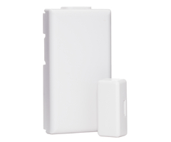
ADEMCO 5811
One Zone Door/Window Transmitter
Installation and Setup Guide
GENERAL INFORMATION
The 5811 is a single zone Door/Window Transmitter,
compatible with alarm systems that support 5800 ser
ies wireless
devices. 5811 has a unique serial number permanentl
y assigned during manufacture, which must be entere
d into the control
panel upon installation.
NOTES
•
Refer to the panel’s installation instructions for
programming details.
•
During programming of the control unit, 5811 trans
mitters should be treated as “RF” (i.e. supervised
RF) Type.
MOUNTING
Choose a mounting location for the 5811 where the d
evice is stationary and the magnet is mounted to th
e moving part of the
door or window. To verify adequate signal strength,
conduct the Go/No Go test (see control’s instructi
ons) on the 5811 before
mounting permanently.
1.
Install the Battery
by inserting one edge of the battery under one of
the two plastic battery retainer clips, then pressi
ng
down firmly to snap it beneath both clips; see
figure 1
.
2.
Mount the 5811 using double-faced tape
(supplied) by affixing it to the back of the unit a
nd mounting the unit in place.
Use screws (optional) if desired; see
figure 2
. Mount the magnet (supplied) near the alignment m
arks on the case (see
Diagram).
Replacing an existing unit:
The back-mounting plate must be replaced when repla
cing the 5811. Use
standard installation practices when removing the u
nit to avoid any damage to the mounting surface.
3. Engage the case tabs (see
figure 2
), then rotate the housing to close. Engage the lat
ch with firm pressure to close and
lock.
BATTERY REMOVAL
1. Open the housing by inserting a flat blade screw
driver into latch and twisting gently.
2. Remove the old battery cell using a small flat s
crewdriver into the latch and gently twisting it un
til the cover becomes
removable (see figure 3).
5811-005-V1
BATTERY
(+ SIDE UP)
REED
SWITCH
PRESS DOWN FIRMLY TO
SNAP BATTERY UNDER
BOTH CLIPS
MAGNET
ALIGNMENT
MARKS
INSERT BATTERY
EDGE UNDER ONE CLIP
A
B
BATTERY
RETAINER
CLIPS
5811-003-V2
REED
LATCH
R
O
T
A
T
E
T
O
C
L
O
S
E
MAGNET
MOUNTING
HOLES
MAX GAP
3/4"
CASE
TABS
SCREWDRIVER
(NO)
5811-006-V1
SCREWDRIVER
(CORRECT)
PLACE TIP OF FLAT SCREW
DRIVER BETWEEN EDGE OF
BATTERY AND PLASTIC CASE
AS SHOWN. POSITIONING
SCREWDRIVER AT ANY OTHER
CORNER MAY CAUSE DAMAGE
TO DEVICE.
CAREFULLY PRY UP WHILE
TWISTING TO REMOVE BATTERY.
A
B
X
X
IC: #
FCC ID: #
IC: xxxx-xxxx
FCC ID: xxxxxxxxxx
Figure 1. Battery Installation
Figure 2. Mounting
F
igure 3. Battery Removal
SPECIFICATIONS
Dimensions:
2-1/8” (55mm) x 1-3/16" (30mm) x 1/4” (7mm)
Operating Conditions:
23° F (-5° C) to 120° F (50° C)
Relative Humidity 95%, (non-condensing)
Replacement Battery:
Panasonic/Sener CR2032 and Duracell DL2032
1
3
2
NOTE
: The FCC ID and IC Certification number is on the
back of the plastic case, or see the diagram in the
“Figure 3: Battery
Removal”
section for the alternate location.
FEDERAL COMMUNICATIONS COMMISSION (FCC) & ISED
The user shall not make any changes or modification
s to the equipment unless authorized by the Install
ation Instructions or User's Manual.
Unauthorized changes or modifications could void th
e user's authority to operate the equipment.
FCC / ISED STATEMENT
This device complies with Part 15 of the FCC Rules,
and ISED’s license-exempt RSSs. Operation is subje
ct to the following two conditions: (1)
This device may not cause harmful interference, and
(2) This device must accept any interference recei
ved, including interference that may
cause undesired operation.
Cet appareil est conforme à la partie 15 des règles
de la FCC et exempt de licence RSS d’ISED. Son fon
ctionnement est soumis aux
conditions suivantes: (1) Cet appareil ne doit pas
causer d’interférences nuisibles. (2) Cet appareil
doit accepter toute interférence reçue y
compris les interférences causant une réception ind
ésirable.
Responsible Party / Issuer of Supplier’s Declaratio
n of Conformity: Ademco Inc., a subsidiary of Resid
eo Technologies, Inc., 2 Corporate Center Drive., M
elville,
NY 11747, Ph: 516-577-2000
TO THE INSTALLER:
Regular maintenance and inspection (at least annua
lly) by the installer and frequent testing by the u
ser are vital to continuous satisfactory
operation of any alarm system. The installer shoul
d assume the responsibility of developing and offer
ing a regular maintenance program to the user, as w
ell as
acquainting the user with the proper operation and
limitations of the alarm system and its component p
arts. Recommendations must be included for a specif
ic
program of frequent testing (at least weekly) to in
sure the system’s operation at all times.
REFER TO THE INSTALLATION INSTRUCTIONS FOR THE CONT
ROL WITH WHICH THIS DEVICE IS USED, FOR DETAILS REG
ARDING
LIMITATIONS OF THE ENTIRE ALARM SYSTEM.
The product should not be disposed of with other ho
usehold waste. Check for the nearest authorized col
lection centers or authorized
recyclers. The correct disposal of end-of-life equi
pment will help prevent potential negative conseque
nces for the environment and human
health.
Any attempt to reverse-engineer this device by deco
ding proprietary protocols, de-compiling firmware,
or any similar actions is strictly
prohibited.
SUPPORT & WARRANTY INFORMATION
For the latest documentation, online support and, p
atent information, please go to:
www.resideo.com
For the latest warranty information, please go to:
www.security.honeywellhome.com/warranty
.
The Honeywell Home Trademark is used under license
from Honeywell International Inc.
This product manufactured by Resideo Technologies a
nd its affiliates
2 Corporate Center Drive, Suite 100
P.O. Box 9040, Melville, NY 11747
2020 Resideo Technologies, Inc.
www.resideo.com
Ê800-03928V2DÇŠ
800-03928V2D 4/15 Rev. D
- Uploaded