Honeywell Home PROTAKEOVER Installation Instructions - Dated 6/19 Rev. B
Related Products
Document Transcript
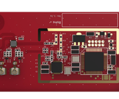
PROTAKEOVER
Wireless Converter Communication Module
Installation and Setup Guide
General Information
The Takeover Module allows Resideo PRO Series contr
ol panels to communicate with previously installed
wireless sensors and
modules that transmit on the following frequencies:
319.5MHz, 345MHz, 433.42 and 433.92MHz. Refer to th
e PROTAKEOVER Compatibility Chart (p/n 800-24626 or
later).
The module connects directly to the control panel a
nd is powered via the control panel’s connection.
Note:
The module should not be used with life safety sen
sors such as Smoke, Heat or CO detectors.
INSTALLING THE MODULE
!
Ensure that all electrical power is removed from th
e control before installing the module. Unplug the
power supply and disconnect the backup battery.
1. Remove electrical power (if applied). Refer to
the
System Shutdown
section for additional
information.
2. Remove the screw securing the control to the
wall mount. Rotate the Control Panel and lift it
from the wall mount, being careful not to
damage the wiring.
4. Remove the right side cover.
5. Set the rotary switch on the PROTAKEOVER
module to the setting associated with the
existing wireless sensors and modules and
the Control Panel. Refer to Table 1 for the
supported protocols.
6. Insert the PROTAKEOVER module into the
slot on the right side of the Control Panel as
shown and ensure the receptacle is securely
seated on the Control Panel’s edge
connector. Secure with the provided screw.
7. Reinstall the access cover, taking care to
avoid bending the contacts on the module.
8. Remove the existing wall mount and replace
with the wall mount (containing the integrated
antenna) provided with PROTAKEOVER
module.
Note:
To avoid damaging the connector pins on the
module, do not force the rear case du
ring the
installation.
9. Install the control on the replacement wall
mount and secure with the screw.
COVER
PROTAKEOVER
MODULE
QS-065-V0
SCREW
Figure 1. Installing the PROTAKEOVER Module
Protocol
PROA7
Series
5800
0
2GIG
1
DSC
2
ITI/Qolsys
3
Bosch
4
Table 1 – Rotary Switch Settings
QS-072-V0
REMOVE
SET
SCREW
INSTALL
SET
SCREW
PROA7PLUS
1
2
3
4
RELEASE
TOP CLEATS
WALL
PLATE
MOUNTING
SCREWS
(4-TYP)
PROA7PLUS
SNAP
INTO
PLACE
ENGAGE
TOP CLEATS
WALL
TAMPER
SCREW
(IF REQ’D)
INSTALL
REMOVE
Figure 2. Replacing the Wall Mount
PROGRAMMING
Programming associated with the PROTAKEOVER module
is accomplished as part of the control panel progra
mming. Refer to the control
panel installation and setup guide for additional i
nformation.
SPECIFICATIONS
Board Dimensions
: .............................. 2.64” (67mm) L x1.
18” (30mm) W x 0.063” (1.6mm) D
Current Drain
: < 35mA, standby
Input Voltage:
..................................... 5V (provide
d by the control panel)
Environmental
Operating Temperature: ........................ -10
°F (-23°C) to 131°F (55°C) (for compliance agency 3
2°F (0°C) to 120°F (49°C)
Storage Temperature: ........................... -4
0°F (-40°C) to 158°F (70°C)
Humidity: .........................................
...... 10 to 90% relative humidity, non-condensing
(for compliance agency 0% to 85%)
REFER TO THE INSTALLATION AND SETUP GUIDE FOR THE C
ONTROL WITH WHICH THIS DEVICE IS USED FOR WARRANTY
INFORMATION AND LIMITATIONS OF THE ENTIRE SYSTEM.
FEDERAL COMMUNICATIONS COMMISSION ISED STATEMENTS
The user shall not make any changes or modification
s to the equipment unless authorized by the Install
ation Instructions or User's Manual. Unauthorized
changes or modifications could void the user's auth
ority to operate the equipment.
FCC CLASS B STATEMENT
This equipment has been tested to FCC requirements
and has been found acceptable for use. The FCC requ
ires the following statement for your
information:
This equipment generates and uses radio frequency e
nergy and if not installed and used properly, that
is, in strict accordance with the manufacturer's
instructions, may cause interference to radio and t
elevision reception. It has been type tested and fo
und to comply with the limits for a Class B computi
ng
device in accordance with the specifications in Par
t 15 of FCC Rules, which are designed to provide re
asonable protection against such interference in a
residential installation. However, there is no guar
antee that interference will not occur in a particu
lar installation. If this equipment does cause inte
rference
to radio or television reception, which can be dete
rmined by turning the equipment off and on, the use
r is encouraged to try to correct the interference
by
one or more of the following measures:
• If using an indoor antenna, replace it with a qua
lity outdoor antenna.
• Reorient the receiving antenna until interference
is reduced or eliminated.
• Move the radio or television receiver away from t
he receiver/control.
• Move the antenna leads away from any wire runs to
the receiver/control.
• Plug the receiver/control into a different outlet
so that it and the radio or television receiver ar
e on different branch circuits.
• Consult the dealer or an experienced radio/TV tec
hnician for help.
ISED CLASS B STATEMENT
This Class B digital apparatus complies with Canadi
an ICES-003.
Cet appareil numérique de la classe B est conforme
à la norme NMB-003 du Canada.
FCC / ISED STATEMENT
This device complies with Part 15 of the FCC Rules,
and ISED’s license-exempt RSSs. Operation is subje
ct to the following two conditions: (1) This
device may not cause harmful interference (2) This
device must accept any interference received, inclu
ding interference that may cause undesired
operation.
Cet appareil est conforme à la partie 15 des règles
de la FCC et exempt de licence RSS d’ISED. Son fon
ctionnement est soumis aux conditions
suivantes: (1) Cet appareil ne doit pas causer d’in
terférences nuisibles. (2) Cet appareil doit accept
er toute interférence reçue y compris les interfére
nces
causant une réception indésirable.
!
RF Exposure Warning
The antenna(s) used for this transmitter must be in
stalled to provide a separation distance of at leas
t 7.8 inches (20 cm) from all persons and
must not be co-located or operating in conjunction
with any other antenna or transmitter except in acc
ordance with FCC and ISED multi-
transmitter product procedures.
Mise en Garde
Exposition aux Frequences Radio:
La/les antenne(s) utilisée(s) pour cet émetteur do
it/doivent être installée(s) à une distance de sépa
ration
d'au moins 20 cm (7,8 pouces) de toute personne et
ne pas être située(s) ni fonctionner parallèlement
à tout autre transmetteur ou antenne,
excepté en conformité avec les procédures de produi
t multi transmetteur FCC et ISEDs.
Responsible Party / Issuer of Supplier’s Declaratio
n of Conformity: Ademco Inc., a subsidiary of Resid
eo Technologies, Inc., 2 Corporate Center Dr.,
Melville, NY 11747, Ph: 516-577-2000.
The product should not be disposed of with other ho
usehold waste. Check for the nearest authorized col
lection centers or authorized recyclers. The
correct disposal of end-of-life equipment will help
prevent potential negative consequences for the en
vironment and human health.
Any attempt to reverse-engineer this device by deco
ding proprietary protocols, de-compiling firmware,
or any similar actions is strictly prohibited.
WARRANTY & SUPPORT
For Documentation and Support visit: www.resideo.co
m.
For Warranty information visit: www.security.honeyw
ellhome.com/warranty.
www.resideo.com
Resideo Technologies, Inc.
2 Corporate Center Drive, Suite 100
P.O. Box 9040, Melville, NY 11747
© 2020 Resideo Technologies, Inc. All rights reserv
ed.
The Honeywell Home trademark is used under license
from Honeywell International, Inc.
This product is manufactured by Resideo Technologie
s, Inc. and its affiliates.
800-25182B 6/19 Rev. B
- Uploaded