Honeywell Home PROWIFIZW Installation Instructions - Dated 3/19 Rev. A
Related Products
Document Transcript
1
PROWIFIZW Wireless
Communication Module
Installation and Setup Guide
General Information
The Communication Module allows the Control Panel t
o communicate with the Central Station, PROWLTOUCH
Wireless Touchscreen
and Amazon Alexa via Wi-Fi. The
PROWIFIZW
communications module is intended to provide compa
tible Control Panels with a Wi-Fi
connection as well as connection with and the abili
ty to control Z-Wave devices. The module connects d
irectly to the Control Panel and
is powered via the Control Panel’s connection.
Compatible Control Panels:
PROA7PLUS Series – Quick Installation Guide P/N
800-25079 or higher
.
PROH8PLUS Series - Quick Installation Guide
P/N
800-25093 or higher.
Installing the Module in the PROA7PLUS
!
Ensure that all electrical power is removed from th
e control before installing the module. Unplug the
power supply and disconnect the backup battery.
1. Affix the provided FCC/IC label (P/N 800-25180 f
or
the PROWIFIZW) on the control’s case back (refer to
Figure 1).
2. If the Control Panel is not powered up proceed t
o step
7. If the Control Panel is powered up, disarm the
system and wait 30-60 seconds:
3. Unplug the power supply.
4. Remove the screw securing the control to the wal
l or
desk mount.
5. Remove the control from the wall or desk mount.
6. Disconnect the battery.
QS-060-V0
CONTAINS MODULE:
FCC ID: RI7LE910NAV2
IC:5131A-LE910NAV2
CONTAINS MODULE:
FCC ID: RI7LE910NAV2
IC:5131A-LE910NAV2
This device complies with Part 15 of the FCC Rules,
and ISED’s license-exempt RSSs. Operation is subjec
t
to the following two conditions: (1) This Device ma
y
not cause harmful interference. (2) This device mus
t
accept any interference received, including
interference that may cause undesired operation.
Figure 1. FCC/IC Label Location
7. Remove the left side cover from the control.
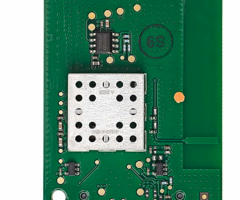
8. Insert the PROWIFIZW module into the slot on the
left
side of the control as shown in Figure 2 and ensure
the receptacle is securely seated on the control’s
edge connector.
9. Secure with the screw.
10. Install the left side cover.
11. Connect the battery.
12. Install the control on the wall or desk mount.
13. Plug the power supply into a 24-hour, 110VAC
unswitched outlet.
QS-058-V0
COVER
PROWIFIZW
MODULE
SCREW
Figure 2. Installing the PROWIFIZW Module
Installing the Module in the PROH8PLUS Series
!
Ensure that all electrical power is removed from th
e Control Panel before installing the module. Unplu
g
the power supply and disconnect the backup battery
and earth ground.
1. Affix the provided FCC/IC label (P/N 800-25180 f
or the
PROWIFIZW) on the PROH8PLUS cabinet (refer to
Figure 3)
2. If the Control Panel is not powered up proceed t
o
step 5. If the Control Panel is powered up, disarm
the
system and wait 30-60 seconds:
3. Unplug the power supply.
4. Disconnect the battery.
BATT+ BATT -
AUX/BELL_OC LED
RUN LED
IB2/ACTIVE LED
RESERVED LED
TRIGGER 2
12V
GND
TRIGGER 1
BATTERY POWER LED
NOT
USED
HI
LO
ZONE 2
2000
OHMS
EOLR
ZONE 1
USE FOR
2-WIRE SMOKE
DETECTORS
MAXIMUM
NUMBER OF
2-WIRE SMOKE
DETECTORS
ON ZONE 1
IS 16
ZONE 1
2000
OHMS
EOLR
HI
HI
LO
LO
HI
LO
2000
OHMS
EOLR
ZONE 3
2000
OHMS
EOLR
ZONE 4
HI
HI
LO
LO
2000
OHMS
EOLR
ZONE 5
2000
OHMS
EOLR
ZONE 6
HI
HI
LO
LO
2000
OHMS
EOLR
ZONE 7
2000
OHMS
EOLR
ZONE 8
EARTH
GROUND
300-10211
13.5 VDC, 1.8A
POWER
SUPPLY TO
10VAC
UNSWITCHED
OUTLET
(24HR)
DC+
DC -
DC+
DC -
ADTHYBWL-Series - Summary of Connections
800-24129 2/18 Rev.A
RJ-45
CONNECTOR
TAMPER
SWITCH
BLACK
RED
RECHARGEABLE BATTERY
(12V, 7AH)
SEALED LEAD ACID TYPE
SEE
INSTRUCTIONS**
FOR PROPER
GROUNDING
TO INTERNET
CONNECTION
© 2018 ADT Security Services
GND
AUX
SLOT 3
GENERAL
SLOT 2
WiFi / ZWAVE
SLOT 1
LTE
8-PIN TRIGGER
CONNECTOR
AC POWER LED
TRIGGER OUTPUT 1: 100mA MAX
TRIGGER OUTPUT 2: 100mA MAX
AUX OUTPUT LED
NOT
USED
24-HR BATTERY
STANDBY REQUIRED
FOR FIRE
INSTALLATIONS.
USE 12V, 7AH
BATTERY FOR
120mA AUX POWER.
SEE INSTRUCTIONS.
BATTERY CAPACITY FOR EMERGENCY
BURGLARY STANDBY USE AT LEAST
4 HRS.
CHARGING VOLTAGE 13.8VDC.
MAXIMUM CHARGING CURRENT
650mA.
SEALED LEAD-ACID TYPE. BATTERY
NORMALLY NEED NOT BE REPLACED
FOR AT LEAST THREE YEARS
TO DETERMINE TOTAL STANDBY LOAD
ON BATTERY, ADD 100mA TO TOTAL OF
AUX. POWER AND REMOTE TOUCHPAD
CURRENTS
WEEKLY TESTING IS REQUIRED TO ENSURE PROPER OPERATION OF THIS SYSTEM. IN ADDITION, THIS
SYSTEM MUST BE CHECKED BY A QUALIFIED TECHNICIAN AT LEAST ONCE EVERY THREE (3) YEARS.
BLACK: TOUCHPAD GND (-) RETURN
YELLOW: TOUCHPAD IB2A
GREEN: TOUCHPAD IB2B
RED: TOUCHPAD POWER (+)
AUX. PWR
OUTPUT
10.5-13.8VDC
200mA MAX.
(120mA MAX.
FOR UL
INSTALLATIONS)
ALL OUTPUTS
ARE POWER
LIMITED.
}
CONNECTION OF
THE FIRE ALARM
SIGNAL TO A FIRE
ALARM HEAD-
QUARTERS OR
CENTRAL STATION
SHALL BE PERMIT-
TED ONLY WITH
THE PERMISSION
OF THE LOCAL
AUTHORITY HAVING
JURIDICTION. THE
BURGLAR ALARM
SIGNAL SHALL NOT
BE CONNECTED
TO A POLICE
EMERGENCY
NUMBER
THIS EQUIPMENT
SHOULD BE
INSTALLED
IN ACCORDANCE
WITH THE NATIONAL
FIRE PROTECTION
ASSOCIATION'S
STANDARD 72
(NATIONAL FIRE
PROTECTION
ASSOCIATION,
BATTERYMARCH
PARK, QUINCY,
MA 02169). PRINTED
INFORMATION
DESCRIBING
INSTALLATION,
TESTING,
MAINTENANCE,
EVACUATION
PLANNING AND
REPAIR SERVICE IS
TO BE PROVIDED
WITH THIS
EQUIPMENT.
820 OHMS
EOLR
ALARM
OUTPUT
10.5–13.8VDC,
2A MAX. (600mA
MAX. FOR UL
USAGE, INCLUDING
AUX POWER)
STEADY FOR
BURGLARY/PANIC,
TEMPORAL PULSE
SOUNDING FOR FIRE.
USE 702 SIREN, OR
12V BELL. SEE
INSTRUCTIONS.
FOR BELL
SUPERVISION, AND
CONNECT RESISTOR
DIRECTLY ACROSS
EXTERNAL SOUNDER.
WTP100
TOUCHPAD
1501 Yamato Road
Boca Raton, Florida 33431
A L A R M
S TAT U S
CANCEL
PA N I C
O F F
C O D E
C H I M E
I N S TA N T
R E A DY
T E S T
B Y PA S S
M A X
STAY
AWAY
2
3
1
5
6
4
8
9
7
0
#
T RO U B L E
** FOR COMPLETE INFORMATION SEE INSTRUCTIONS 800-24126 OR HIGHER
-
+
A
B
MAX. ZONE RESISTANCE: (EACH ZONE) 300 OHMS (PLUS EOLR)
(USE EOLR PART NUMBER P4100 PART OF KIT SAHDWR1)
ASSEMBLED IN MEXICO
ETL Listed
Household Fire
and Burglar
Warning Unit
800-21465 10/15 Rev.A
3091091
Conforms to UL STD 985, 1023, 1635
Classified to ANSI/SIA CP01-2010
Model LCP500-L
800-24232 3/18 Rev A
HONEYWELL GRIP HYBRID CONTROLLER
FCC / IC STATEMENT
This device complies with Part 15 of the FCC Rules, and RSS 210 of IC. Operation is subject to the following two conditions:
(1) This Device may not cause harmful interference.
(2) This device must accept any interference received, including interference that may cause undesired operation.
FCC ID: CFS8DL-GRIPH
IC: 573F-GRIPH
HVIN: GRIPH
For Patent Information see: www.honeywell.com/paten
ts
Country of Origin: Mexico
PROH8-060-007-V0
CONTAINS MODULE:
FCC ID: RI7LE910NAV2
IC:5131A-LE910NAV2
CONTAINS MODULE:
FCC ID: RI7LE910NAV2
IC:5131A-LE910NAV2
Figure 3. FCC/IC Label Location 5. Install the PROWIFIZW on the edge connector on t
he
PCB (refer to Figure 4). Ensure the receptacle is
securely seated on the edge connector.
6. Secure the module with the provided screw.
7. Reconnect the earth ground and battery.
8. Plug the power supply into a 24-hour, 110VAC
unswitched outlet.
PROH8-060-003-V0
SCREW
PROWIFIZW
MODULE
GENERAL
WiFi
BATT+ GND
LTE
TX
RX GND
TX
RX GND
EXT
INT
Figure 4. Installing the PROWIFIZW Module
Programming
Note:
The PROWIFIZW requires a router and internet servi
ce for Wi-Fi connection.
1. Programming associated with the PROWIFIZW module
as well as the inclusion/exclusion of Z-Wave devic
es is conducted through
the AlarmNet 360™ Programming Tool. On a laptop, PC
or Smart Device, go to www.alarmnet360.com.
2. When programming is complete, perform a Communic
ations Test.
Specifications
REFER TO THE INSTALLATION AND SETUP GUIDE FOR THE C
ONTROL WITH WHICH THIS DEVICE IS USED FOR WARRANTY
INFORMATION AND LIMITATIONS
OF THE ENTIRE SYSTEM.
FEDERAL COMMUNICATIONS COMMISSION & ISED STATEMENTS
The user shall not make any changes or modification
s to the equipment unless authorized by the Install
ation Instructions or User's Manual. Unauthorized c
hanges or
modifications could void the user's authority to op
erate the equipment.
FCC CLASS B STATEMENT
This equipment has been tested to FCC requirements
and has been found acceptable for use. The FCC requ
ires the following statement for your information:
This equipment generates and uses radio frequency e
nergy and if not installed and used properly, that
is, in strict accordance with the manufacturer's in
structions, may cause
interference to radio and television reception. It
has been type tested and found to comply with the l
imits for a Class B computing device in accordance
with the specifications in
Part 15 of FCC Rules, which are designed to provide
reasonable protection against such interference in
a residential installation. However, there is no g
uarantee that
interference will not occur in a particular install
ation. If this equipment does cause interference to
radio or television reception, which can be determ
ined by turning the
equipment off and on, the user is encouraged to try
to correct the interference by one or more of the
following measures:
• If using an indoor antenna, replace it with a qua
lity outdoor antenna.
• Reorient the receiving antenna until interference
is reduced or eliminated.
• Move the radio or television receiver away from t
he receiver/control.
• Move the antenna leads away from any wire runs to
the receiver/control.
• Plug the receiver/control into a different outlet
so that it and the radio or television receiver ar
e on different branch circuits.
• Consult the dealer or an experienced radio/TV tec
hnician for help.
Responsible Party / Issuer of Supplier’s Declaratio
n of Conformity: Ademco Inc., a subsidiary of Resid
eo Technologies, Inc., 2 Corporate Center Dr., Melv
ille, NY 11747, Ph:
516-577-2000.
ISED CLASS B STATEMENT
This Class B digital apparatus complies with Canadi
an ICES-003.
Cet appareil numérique de la classe B est conforme
à la norme NMB-003 du Canada.
FCC / ISED STATEMENT
This device complies with Part 15 of the FCC Rules,
and ISED’s license-exempt RSSs. Operation is subje
ct to the following two conditions: (1) This device
may not cause
harmful interference (2) This device must accept an
y interference received, including interference tha
t may cause undesired operation.
Cet appareil est conforme à la partie 15 des règles
de la FCC et exempt de licence RSS d’ISED. Son fon
ctionnement est soumis aux conditions suivantes: (1
) Cet appareil ne
doit pas causer d’interférences nuisibles. (2) Cet
appareil doit accepter toute interférence reçue y c
ompris les interférences causant une réception indé
sirable.
!
RF Exposure Warning
The antenna(s) used for this transmitter must be in
stalled to provide a separation distance of at leas
t 7.8 inches (20 cm) from all persons and
must not be co-located or operating in conjunction
with any other antenna or transmitter except in acc
ordance with FCC and ISED multi-
transmitter product procedures.
Mise en Garde
Exposition aux Frequences Radio: La/les antenne(s)
utilisée(s) pour cet émetteur doit/doivent être ins
tallée(s) à une distance de séparation
d'au moins 20 cm (7,8 pouces) de toute personne et
ne pas être située(s) ni fonctionner parallèlement
à tout autre transmetteur ou antenne,
excepté en conformité avec les procédures de produi
t multi transmetteur FCC et ISEDs.
Note:
The product should not be disposed of with other
household waste. Check for the nearest authorized c
ollection centers or authorized recyclers.
The correct disposal of end-of-life equipment will
help prevent potential negative consequences for th
e environment and human health.
USE OF THESE PRODUCTS IN COMBINATION WITH NON-HONEY
WELL PRODUCTS IN A WIRELESS MESH NETWORK, OR TO ACC
ESS, MONITOR OR CONTROL DEVICES IN A WIRELESS
MESH NETWORK VIA THE INTERNET OR ANOTHER EXTERNAL W
IDE AREA NETWORK, MAY REQUIRE A SEPARATE LICENSE FR
OM SIPCO, LLC. FOR MORE INFORMATION, CONTACT
SIPCO, LLC OR IPCO, LLC AT 8215 ROSWELL RD., BUILDI
NG 900, SUITE 950, ATLANTA, GA 303350, OR AT WWW.SI
PCOLLC.COM OR WWW.INTUSIQ.COM
SUPPORT & WARRANTY
For the latest documentation and online support inf
ormation, please go to:
https://mywebtech.honeywellhome.com
For the latest warranty information, please go to:
https://www.security.honeywellhome.com/hsc/resource
s/wa/index.html
For patent information, please go to: www.resideo.c
om/patent
MyWebTech
Warranty
Patents
This product manufactured by Resideo and its affili
ates. The Honeywell Home Trademark is used under
license from Honeywell International Inc.
Ê800-25179mŠ
800-25179 3/19 Rev. A
2 Corporate Center Drive
Melville, New York 11747
© 2019 Resideo Technologies, Inc.
www.resideo.com
Board Dimensions:
1.625” W x 2.625” L x 0.3125” D
Input Voltage Range:
3.6 – 14V, Max 17V
Current Drain: 250mA (PROA7PLUS)
72mA (PROH8PLUS)
Input Voltage:
3.5V ( PROA7PLUS )
13.5V (PROH8PLUS)
Temperature:
32°F (0°C) to 140°F (60°C)
- Uploaded