Honeywell LTE-L57V - Installation Manual
Related Products
Related Categories
Document Transcript
LTE
-L57
V / LTE
-L57C
Cellular
Communication Modules
Installation
Guide
General Information
The
LTE
-L57V
/ LTE-
L57C
Cellular
Communication Modules allow the LYNX Touch
L5210
and L7000
controls
to
communicate with the Central Station
via the
LTE
cellular
network.
See
LYNX Touch Series Installation and Setup Guide (
p/n
800
-19974V1
or higher)
for additional installation and
programming information.
Installing the Communication Module
in the LYNX Touch Series
Control
1. Install the provided FCC label (
LTE
-L57V
: 800-
23737
or
LTE
-L57C: 800-
23737
-1) on the control’s case
back (see diagram).
2. Release the LYNX Touch front case from the back
case by depressing the two locking tabs at the top of
the unit with the blade of a medium size screwdriver
(see diagram below).
3. Install the
communication module
into the LYNX
Touch control front case as shown. Ensure that the
connector board is properly seated into the
receptacle on the control.
4. Secure the
module
with the three provided screws.
5. Enable the
communication module
, configure alarm
reporting and module supervision and register the
device. Refer to the “Program the Radio” and
“Diagnostics” sections in the LYNX Touch Series
Installation
& Setup Guide
(p/n
800-
19974V1 or higher
).
Typical FCC/IC Label Location
(L5210 shown)
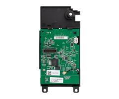
Installing the LTE
-
L57 Communication Module in the LYNX Touch
(L5210 Shown)
Initial Power Up Note
Upon initial communicator
power up, a network
initialization sequence
begins
and the LYNX co
ntrol
displays the following:
SIM not yet provi
sioned.
Please wait. WARNING
–
Do not reset the panel!!!
This sequence may take up
to 15 minutes.
Do not reset
power during this
initialization time
. After the
communicator has
completed network
initialization, subsequent
resets or power ups can take
up
to 90 seconds.
Ê800-23726HŠ
800-
23726 10/17 Rev B
Checking Signal Strength
When choosing a suitable mounting location, check the communicator’s signal strength to ensure pr
oper operation. For
most installations, using the module’s internal antenna, mounting the control as high as practical, and avoiding large metal
components provides adequate signal strength for proper operation. Use the “
Cell
Information” screen to display
signal
strength (in dBm).
Select:
Security > More > Tools > [
Installer
Code] > Program > Comm. Diagnostics >
Cell
Information
Primary Site
QOS
Level Signal strength is displayed by a series of 1 to 5 stars (* weak to ***** strong) or “Not Present” if
the
re is no signal. To ensure a reliable installation at least 2 (**) stars should consistently be present.
If necessary, relocate the Control to obtain better signal strength (press
Cell
Information
again to refresh the reading) or
install an external ante
nna.
Specifications
Voltage Input
5V (provided by the control panel)
Current
Idle
30
mA, standby
Transmit
490
mA,
max
transmit
Environmental
Operating
Temperature
-
20ºC to +55ºC (for compliance
agency: 0ºC to +49ºC)
Storage
Temperature
-40º
C to +70ºC
Humidity
0 to 95% relative humidity, non
-
condensing (for compliance agency
0% to 85%)
Antenna
•
Penta
-
Band diversity antennas
for LTE
•
Supports LTE Bands 12, 13, 5,
4 and 2
External Antenna Kit
CELL
-
ANT
SMA
Important Note About External Antennas
If an external cellular radio antenna is used, the antenna may
be installed or replaced ONLY by a professional installer.
To the Installer
LTE
-57V:
The external antenna gain shall not exceed 6.94 dBi
for 700MHz, 6 dBi for 1700MHz
and 9.01 dBi for 1900MHz
.
LT
E-L57C:
The external antenna gain shall not exceed 6.63
dBi for 700MHz & 850MHz, 6 dBi for 1700MHz
and 8.51 dBi
for 1900MHz.
Support & Warranty
For the latest documentation and online support, please go to:
https://mywebtech.honeywell.com/
For the latest warranty information, please go to:
www.honeywell.com/security/hsc/resources/wa
.
For patent information, see
www.honeywell.com/patents
MyWebTech
Warranty
Patents
FEDERAL COMMUNICATIONS COMMISSION (FCC) STATEMENTS
The user shall not make any changes or modifica
tions to the equipment unless authorized by the Installation Instructions or User's Manual. Unauthorized changes or
modifications could void the user's authority to operate the equipment.
FCC CLASS B STATEMENT
This equipment has been tested to FCC require
ments and has been found acceptable for use. The FCC requires the following statement for your information:
This equipment generates and uses radio frequency energy and if not installed and used properly, that is, in strict accordanc
e with the manufacturer's instructions, may cause
interference to radio and television reception. It has been type tested and found to comply with the limits for a Class B com
puting device in accordance with the specifications
in Part 15 of FCC Rules, which are designed to prov
ide reasonable protection against such interference in a residential installation. However, there is no guarantee that
interference will not occur in a particular installation. If this equipment does cause interference to radio or television re
ception, whi
ch can be determined by turning the
equipment off and on, the user is encouraged to try to correct the interference by one or more of the following measures:
•
If using an indoor antenna, have a quality outdoor antenna installed.
•
Reorient the receiving antenna until interference is reduced or eliminated.
•
Move the radio or television receiver away from the receiver/control.
•
Move the antenna leads away from any wire runs to the receiver/control.
•
Plug the receiver/control into a different outlet so tha
t it and the radio or television receiver are on different branch circuits.
•
Consult the dealer or an experienced radio/TV technician for help.
I
NDUSTRY CANADA CLASS B STATEMENT
This Class B digital apparatus complies with Canadian ICES
-003.
Cet appareil
numérique de la classe B est conforme à la norme NMB
-003 du Canada.
FCC / IC STATEMENT
This device complies with Part 15 of the FCC Rules, and Industry Canada’s license-exempt RSSs
. Operation is subject to the following two conditions: (1) This device may not
cause harmful interference (2) This device must accept any interference received, including interference that may cause undes
ired operation.
Cet appareil est conforme à la partie 15 des règles de la FCC et exempt de licence RSS d’Industrie Canada.
Son fonctionnement est soumis aux conditions suivantes: (1) Cet
appareil ne doit pas causer d' interf
érences nuisibles. (2) Cet appareil doit accepter toute interf
érence reçue y compris les interf
érences causant une r
éception indésirable.
RF Exposure Warni
ng
The antenna(s) used for this transmitter must be installed to provide a separation distance of at least 7.8 in (20 cm) from a
ll persons and must not be co
-located
or operated in conjunction with any other transmitter except in accordance with FCC and IS
ED
multi
-transmitter product procedures.
Mise en Garde
Exposition aux Frequences Radio:
La/les antenne(s) utilisée(s) pour cet émetteur doit/doivent être installée(s) à une distance de séparation d'au moins 20 cm
(7,8 pouces) de toute personne et ne pas êt
re située(s) ni fonctionner parallèlement à tout autre transmetteur ou antenne, excepté en conformité avec les
procédures de produit multi transmetteur FCC et ISED.
2 Corporate Center Drive, Suite 100
P.O. Box 9040, Melville, NY 11747
© 2017 Honeywell International Inc.
www.honeywell.com/security
- Uploaded