Honeywell Lyric LTE Communicators - Install Guide
Related Products
Related Categories
Document Transcript
LYRICLTE-A
LYRICLTE-C
LYRICLTE-V
Installation Instructions
General Information
The Communication Modules allow the Lyric Controlle
r to communicate with the Central Station via the c
ellular radio network. The Lyric
LTE series includes the following models:
•
LYRICLTE-A (US, AT&T network)
[
NOTE
: Use LYRICLTE-A in Lyric Controllers with firmware
version V01.03.06548.482 or later]
•
LYRICLTE-C (Canada)
•
LYRICLTE-V (US, Verizon network) [
NOTE
: Use LYRICLTE-V in Lyric Controllers with firmware
version V01.09.07745.491 or later]
FIRST TIME INSTALLATION NOTE
S
:
•
Before performing the first time installation of t
he communication module, make sure power (both AC a
nd battery) is
removed from the controller and follow the
Installing the Module
(First Time Installation)
steps.
•
The initialization sequence for the LYRICLTE-V comm
unication module may take up to 20 minutes.
Do not
reset power during this time.
Installing the Module (First Time Installation)
1. Install the provided FCC/IC label on the control
’s case back.
LYRICLTE-A & LYRICLTE-C: 800-22830 LYRICLTE-V: 800
-22830-1
2. Remove bezel from right-hand side of control to
expose the
communication module slot. To remove the bezel, pus
h upward then
slide it out.
3. Insert the module into the slot. Push firmly to
mate the edge connector.
4. Replace the bezel.
5. After all other connections are made, power up t
he controller.
Note:
This sequence may take up to 20 minutes he LYRICLT
E-V
communication module.
Do not reset power during this time.
6. Program and register the module during the contr
oller’s initial
association with its AlarmNet 360™ account. Refer t
o the controller’s
Programming Guide for details.
lyric-024-V2
XXXX-XXXXXX
XXXX-XXX
XXXXXXXXX-XX
XXXX-XXXXXX
XXXX-XXX
XXXXXXXXX-XX
WEEKLY TESTING IS REQUIRED TO ENSURE PROPER
OPERATION OF THIS SYSTEM.
For complete
Information see instructions 800-18076 dated XX/XX
.
REQUIRED BATTERIES:
One 7.2VDC Nickel-Metal
Hydride. Rechargeable battery pack kit p/n 300-0386
4-3PIN
or 300-03866. Replace battery kit every four years
.
Do not dispose of in fire, batteries may leak or ex
plode.
This equipment should be installed in accordance w
ith
the National Fire Protection Association's Standard
72,
Chapter 2 (National Fire Protection Assoc.,
Batterymarch Park, Quincy, MA 02169). Printed
information describing proper installation, operati
on,
testing, maintenance, evacuation planning and repai
r
service is to be provided with this equipment.
HONEYWELL LYRIC SMART CONTROLLER
FCC / IC STATEMENT
This device complies with Part 15 of the FCC
Rules, and RSS 210 of IC. Operation is
subject to the following two conditions:
(1) This Device may not cause harmful interfer-
ence. (2) This device must accept any interfer-
ence received, including interference that may
cause undesired operation.
FCC ID: XXXXXXXXX
IC: XXXX-XXX IC MODEL: XXX
Typical FCC/IC Label Location
lyric-025-V1
PUSH UP THEN SLIDE OUT
Removing the Bezel
EXTERNAL
ANTENNA
JACK
PUSH
DOWN
lyric-034-V3
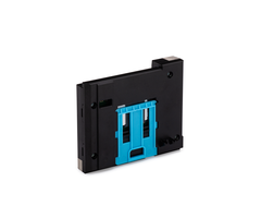
MODULE
Installing the communicator Module
7. Check the signal strength before permanently loc
ating the Lyric Controller. See Checking Signal Str
ength section.
8. Test the communication paths.
Master User:
Security
–
Tools
–
[Master code]
–
Advanced
–
Comm. Test
Installer:
Security
–
Tools
–
[Installer code]
–
Program – Comm. Diagnostics - [
V
] – Test Communication
Press
Send Cellular Message
. Wait for “Ack Received” message.
Press
Send Ethernet Message
. Wait for “Ack Received” message.
“Ack Received” indicates successful communication.
If acknowledgement is not received, try one of the
following:
a. Use an external antenna (see Using an External
Antenna section).
b. Set the communication path to Wi-Fi-only.
Checking Signal Strength
When choosing a suitable mounting location, check t
he communicator’s
signal strength to ensure proper operation. For mos
t installations, using
the module’s internal antenna, mounting the Lyric c
ontroller as high as
practical, and avoiding large metal components prov
ides adequate signal
strength.
Use the Lyric Controller “Cellular Information” scr
een to display signal
strength (in number of bars):
Security
–
Tools
–
[installer code]
–
Program
–
Comm. Diagnostics
–
Cellular Information
Compare the signal strength number of bars displaye
d to the Signal
Strength Guide values at right to ensure adequate s
ignal strength.
If using AlarmNet 360, check that the display is mi
nimum 2 bars.
If necessary, relocate the Controller to obtain bet
ter signal strength (press
Cellular Information
again to refresh the reading).
Signal Strength
Guide
Panel display signal strength:
range of 1-5 bars;
should be minimum 2 bars
AlarmNet 360 Display
:
Must be minimum 2 bars lit.
If adequate signal strength cannot be achieved, an
external antenna should be used. See
Using an External Antenna
section on
the other side.
Ê800-21995yŠ
800-21995 2/17 Rev. E
Communicat
ion
Module Replacement
This procedure is intended only for replacement of
existing communication modules previously installed
and registered in
the Controller.
In the event the communication module needs to be r
eplaced, the Lyric Controller must first be put in
module replacement mode
(“Install Cellular Module”) to avoid causing a tamp
er alarm or damaging the module. Module replacement
mode deactivates tamper
protection and removes power from the module connec
tor for about 15 minutes.
1. Select the
Install
Cellular Module
button.
Master User:
Security
–
Tools
–
[master code] –
Advanced
– Install Cellular
Module
Installer:
Security
–
Tools
–
[installer code]
–
Test – Install Cellular Module
a. Select
Yes
at the prompt to continue.
b. A popup window displays steps for module replac
ement. Keep this
window open until replacement is completed
2. Remove the side bezel. See diagram at right.
3. Remove the communication module from its connect
ion slot by using the
pull tab.
4. Insert the new module into the slot. Push firmly
to mate the edge connector.
5. Replace the bezel.
6. When installation is complete, press
OK
at the replacement steps window.
Confirmation of proper installation appears. Press
OK
to exit.
7. Test the communication path. See step 8 in Insta
lling the Module section.
PUSH UP THEN SLIDE OUT
PULL
TAB
lyric-047-V2
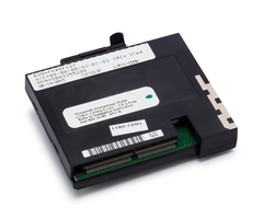
MODULE
Replacing the Module
Using an External Antenna
If adequate signal strength cannot be achieved with
the internal
antenna, an external antenna can be employed. A kit
with an
adapter cable, clamp, and bracket will be required.
A connection
diagram with the adapter kit and a typical antenna
is provided
with the kit.
IMPORTANT NOTE ABOUT EXTERNAL ANTENNAS
If an external cellular radio antenna is used, the
antenna may be
installed or replaced ONLY by a professional instal
ler.
TO THE INSTALLER
LYRICLTE-A, LYRICLTE-C
This device is to be used in mobile or fixed applic
ations only. For mobile
and fixed operating configurations the antenna gain
, including cable
loss, must not exceed
3.25 dBi (US) or 0.6dBi (Canada) at 850 MHz, 5.5 dB
i at 1700 MHz,
2.5dBi at 1900 MHz for satisfying RF exposure compl
iance. Under no
conditions may an antenna gain be used that would e
xceed the ERP
and EIRP power limits as specified in Part 22H and
24E and 27, and IC
RSS-130, RSS-132, RSS-133, and RSS-139.
LYRICLTE-V
This device is to be used in mobile or fixed applic
ations only. For mobile
and fixed operating configurations the antenna gain
, including cable
loss, must not exceed 7.31 dBi at 780 MHz, 7.35 dBi
at 1700 MHz for
satisfying RF exposure compliance. Under no conditi
ons may an
antenna gain be used that would exceed the ERP and
EIRP power
limits as specified in Part 22H and 24E and 27.
RF Exposure
Warning
– The antenna(s) used for this device must be inst
alled to
provide a separation distance of at least 7.8 inche
s (20 cm) from all
persons and must not be co-located or operating in
conjunction with any
other antenna or transmitter except in accordance w
ith FCC and ISED
multi-transmitter product procedures.
Mise en Garde
Exposition aux Fréquences Radio :
La/les antenne(s) utilisée(s) pour
cet émetteur doit/doivent être installée(s) à une d
istance de séparation
d'au moins 20 cm (7,8 pouces) de toute personne et
ne pas être
située(s) ni fonctionner parallèlement à tout autre
transmetteur ou
antenne, excepté en conformité avec les procédures
de produit multi
transmetteur FCC et ISED.
SUPPORT & WARRANTY
For the latest documentation & online support infor
mation, please go to:
https://mywebtech.honeywellhome.com/
For the latest warranty information, please go to:
https://www.security.honeywellhome.com/hsc/resource
s/wa/index.html
For patent information, please go to:
https://www.resideo.com/patent
!
The product should not be disposed of with other ho
usehold
waste. Check for the nearest authorized collection
centers or
authorized recyclers. The correct disposal of end-o
f-life equipment
will help prevent potential negative consequences f
or the
environment and human health.
Specifications
Dimensions: ..
2-5/8”W x 3-1/8”L x 1/2”D
Voltage Input
.. 7.2VDC (provided by the controller)
Current
LYRICLTE-A / LYRICLTE-C:
Idle ..................... 45mA, standby
Transmit max. .... 245mA RMS
LYRICLTE-V:
Idle ..................... 33mA, standby
Transmit max. .... 326mA RMS
Environmental
Operating temperature: -20ºC to +55ºC,
(for compliance agency: 0ºC to +49ºC)
Storage temperature: -40º to +70ºC
Humidity: 0 to 95% relative humidity, non-condensin
g
(for compliance agency 0% to 85%)
Frequency Bands
LYRICLTE-V:
LTE: Triple band, 700 (Bd13) / AWS (Bd4) / 1900MHz
(Bd2)
LYRICLTE-A, LYRICLTE-C:
GSM/GPRS/EDGE: Quad band, 850/900/1800/1900MHz
UMTS/HSPA+: Triple band, 850 (BdV) / AWS (BdIV) / 1
900MHz
(BdII)
LTE: Quad band, 700 (Bd17) / 850 (Bd5) / AWS (Bd4)
/ 1900MHz
(Bd2)
FEDERAL COMMUNICATIONS COMMISSION (FCC) & ISED
STATEMENTS
The user shall not make any changes or modification
s to the
equipment unless authorized by the Installation Ins
tructions or User's
Manual. Unauthorized changes or modifications could
void the user's
authority to operate the equipment.
FCC / ISED STATEMENT
This device complies with Part 15 of the FCC Rules,
and ISED’s
license-exempt RSSs. Operation is subject to the fo
llowing two
conditions: (1) This device may not cause harmful i
nterference (2)
This device must accept any interference received,
including
interference that may cause undesired operation.
Cet appareil est conforme à la partie 15 des règles
de la FCC et
exempt de licence RSS d’ISED. Son fonctionnement es
t soumis aux
conditions suivantes: (1) Cet appareil ne doit pas
causer
d’interférences nuisibles. (2) Cet appareil doit ac
cepter toute
interférence reçue y compris les interférences caus
ant une réception
indésirable.
Responsible Party / Issuer of Supplier’s Declaratio
n of Conformity:
Ademco Inc., a subsidiary of Resideo Technologies,
Inc.,
2 Corporate Center Drive., Melville, NY 11747, ph:
516-577-2000
This product manufactured by Resideo and its affili
ates. The
Honeywell Home Trademark is used under license from
Honeywell
International Inc.
2 Corporate Center Drive, Suite 100
P.O. Box 9040
Melville, NY 11747
2019 Resideo Technologies, Inc.
www.resideo.com
- Uploaded