Interlogix 600-9400-IMAG - Alarm.com ADC-IS-200-LP Image Sensor- Installation Manual
Related Products
Related Categories
Document Transcript
Interlogix part number:
6
00
-
9400
-
IMAG
Alarm.com part number: ADC
-
IS
-
2
00
-
LP
Alarm.com Image Sensor
Installation Guide
1
Copyright © 201
4
Alarm.com. All rights reserved.
Rev 3.
3
PRODUCT SUMMARY
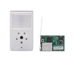
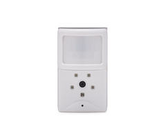
The Image Sensor
is a
pet immune
PIR (passive infrared) motion detect
or with a built
-
in
camera.
The sensor
is designed to
capture
image
s
during alarm
or non
-
alarm events
when motion is detected
.
Users can also initiate image capture on
-
demand to
P
eek
-
I
n
on their property.
Images are stored locally and uploaded
either
automatically
when motion is captured
during alarm events
or manually when requested by the user.
Once uploaded, images are available for viewing on the Alarm.com
W
ebsite or an
Alarm.com
S
mart phone app. The sensor is battery powered, all wireless and simple to
install and operate.
Both an
Alarm.com
module and
a
subscription to an Alarm.com
service plan are required.
Highlighted Features
Battery operated
Communicates wirelessly to
the security control
panel
35 feet by 40 feet detection coverage area
Configurable
PIR
sensitivity and pet immunity settings
Image: QVGA 320x240 pixels
Color Images (except in night vision)
Night vision image capture with infrared flash (black & white)
T
amper
d
etection,
w
alk
t
est
m
ode,
s
upervision
S
e
rvice Plan Options
Image capture features require either a
n Alarm.com
Basic
or
Advanced
Interactive
S
ervice
P
lan
and one of the following Image Sensor add
-
ons:
Image Sensor
Alarms
-
Includes
upload of images from alarm events only.
Image Sensor
Plus
-
Includes
upload of images from alarm events
and
non
-
alarm
events
.
User
s
can configure
Daily View
schedul
es
to receive images automati
cally each
day
or
Peek
-
In
to
initiate
an
on
-
demand
image capture immediately
,
or when the next
motion
occurs.
Users can also request images that are
cap
tured auto
matically while the
system is
A
rmed
A
way
or following
a
D
isarm
from an
A
rmed
A
way
state. Up to 40
captured events can be uploaded per month.
Additional
image
up
loads may be added
in increments of 20 at an additional charge.
HARDWARE COMPATIBILITY
Security Contr
ol Panel:
Interlogix Simon XT
v
1.3 or higher
or
XTi v 1.0 or higher
Alarm.com Module
:
Simon X
T
Module with firmware 146 or
higher
(
XTi
requires
module with firmware 15
1
or higher
)
Required Daughterboard:
Image Sensor
d
aughterboard
(
attache
d
to compatible
Alarm.com module
)
Available Zones:
One zone per Image Sensor installe
d. On the Simon XT only, one
additional zone is required
for
the required da
ughterboard
.
Up to three Image Sensors
may be added
per system.
(Note:
The Alarm.com GSM Module
V4
is required to use
both Image Sensor and emPower
™
.)
HARDWARE INSTALLATION
1.
Create Alarm.com
C
ustomer
A
ccoun
t
-
Select service plan (including Image Sensor
add
-
on) and register the Alarm.com
m
odule serial number
on
the
Alarm.com
Dealer
Webs
ite
(www.alarm.com/dealer)
.
2.
Install Image Sensor Daughterboard
-
Locate the connector on the back of the
daughterboard. Remove the green backing from the daughterboard mounting adhesive.
While the module is
powered down, align the daughterboard
and module
connector
.
P
ress to secure.
(NOTE: Verify module compatibility
before
attaching
.
Once attached,
daughterboard is difficult to remove and removing may damage hardware.
)
3.
Install Alarm.com Module
I
nside
Control
Panel
4.
FOR
SIMON XT ONLY,
Connect Daughterboard Alarm Wire
-
On the XTi panel, the
blue alarm hardwire is not required and should not be connected.
For XTi panels, skip
to step 5.
When using the Simon XT panel,
you must connect the
included
blue wire
from
the “
HW
”
hardwire
output located on the daughterboard
(use “HW” not “C”)
to the
“HW2 IN” (terminal 3)
slot on the Simon XT panel
to enable loc
al alarm activations
.
Once an Image Sensor has been enrolled into the panel, a hardwire zone will
automatically be programmed as “Sensor 39: ISHW
.
”
To ensure alarms are tripped
properly on Image Sensors according to their en
rolled group, the hardwire
sensor group
is automatically configured.
Do NOT alter the sensor group of Sensor 39 ISHW
.
(Note:
On the Simon XT,
t
he panel scr
een will display “Sensor 39: IS
HW Alarm”
regardless of which Image Sensor tripped the alarm.
The Alarm.com
W
ebsite &
notifications
,
and the central station report will indicate the specific Image Sensor that
tripped the alarm.)
5.
Route
D
aughterboard
A
ntenna
-
It is important to be sure that daughterboard antenna
is pulled away from the Alarm.com module.
Follow the panel
-
specific antenna routing
guidelines to optimize sensor range.
Simon XT
-
The antenna should be pulled down off the Alarm.com module
and rout
ed
in a “J” shape
to the left
towards the corner of the panel (when looking
at the panel from
behind.
Simon XTi
-
Bend the antenna at a 90
°
angle ¼ of an inch from the
edge of the
daughterboard. The daughterboard
antenna
should rest inside the panel
’s
plastic
casing
parallel to the
panel
.
6.
Register Module and Test
-
Power
up
the panel and initiate a
comm
-
test to ensure the
Alarm.com
m
odule is properly installed and communicating with the Alarm.com
NOC.
7.
Enroll Sensor in Panel
-
Simon XT
-
To enroll the sensor
on a Simon XT
, follow these steps at the control panel:
a.
Begin with
the batteries removed from the sensor.
b.
On the panel, scroll until the screen displays “System Programming
,
”
and
press OK
.
c.
Enter the installer code (default 4
-
3
-
2
-
1)
,
and press OK.
d.
Scroll up to “Interactive Services
,
”
press OK.
e.
Scroll down to “Image Senso
r Setup
,
”
press OK.
f.
Scroll to “Image Sensor Learn Mode
,
”
press OK.
The screen should display “Power
up or reset I.S.
now
.
”
g.
Insert the batteries into the sensor.
Wait (approximately 20 seconds) for the control
panel screen to display
:
“I.S. [x] Added as Sensor [y]
.
”
The LED on the sensor will
turn solid for ~5 seconds once the sensor has enrolled.
h.
Perform another panel comm
-
test to be sure that Alarm.com receives the updated
device equipment list. This will speed up the sensor initi
alization process.
T
he sensor is now
learned into the panel.
S
ensors are enrolled in group 17 by default.
To change the sensor group, use the
Sensors
menu in System Programming.
Image
Sensors may be enrolled in groups 15, 17, 20,
or
25.
(No chime issued for group 25
.
)
On the Simon XT ,
a
mix of sensor groups 15/17 and 20 are not supported.
If Image
Sensors are in group 15 or 17, they cannot also be in group 20, and vice versa.
After
enrollment, be sure to keep the sensor and panel p
owered
so the sensor can complete
an initialization process with the Alarm.com Network Operations Center.
This process
will take several minutes.
Images cannot be captured until initialization is complete.
Silver shield with
Alarm.com logo
White label
with info
Insert blue alarm hardware into
HW and push to secure
Top of Image Sensor
Daughterboard
Bottom of Simon XT Panel
Blue Alarm Hardwire
from Daughterboard
Connect to “HW 2IN”
(Terminal 3)
Daughterboard
Antenna
Module
DB
Bottom of Simon XTi Panel
Alarm.com Image Sensor
Installation Guide
2
Copyright © 201
4
Alarm.com. All rights reserved.
Rev 3.
3
Simon
XTi
-
To enroll the sensor on a
Simon
X
Ti
, follow these steps at the control panel:
a.
Begin with the batteries removed from the sensor.
b
.
On the
panel, scroll until the screen
shows “Programming”
and press “Enter”.
c
.
Enter the installer code (default 4
-
3
-
2
-
1), and press OK.
d.
Press
“Interactive Services”
.
e.
Press
“
Image Sensor”.
f.
Press “Add”. The screen will display “Reset or power
-
up sensor to enroll...”
g.
Insert the batteries into the sensor.
Wait (approximately 20 seconds) for the control
panel screen to display: “I
S
[x]
s
uccessfully a
dded as
s
ensor [y]” The LED on the sensor
will turn solid for ~5 seconds once the sensor has enrolled.
h.
Perform another panel comm
-
test to be sure that Alarm.com receives the updated
device equipment list. This will speed up the sensor init
ialization process.
T
he sensor is now
learned into the panel.
S
ensors are enrolled in group 17 by default. To
change the sensor group, use the
Sensors
menu in
Programming.
Image Sensors may be
enrolled in groups 15, 17, 20,
or
25. (No chime issued for group 25
.
)
After enrollment, be
sure to keep the sensor and panel powered so the sensor can complete an initialization
process with the Alarm.com Network Operations Center.
This process will take several
minutes.
Images cannot be
captured until initialization is complete.
8.
Choose Sensor Location and Mount
a.
Determine sensor mounting location
based on installation scenario
and criteria
noted
in the “Installation Guidelines
.
”
For best image capture, the target capture
areas sh
ould
be centered in the frame. (
e.g.
If customer wants to capture people
coming through door,
the
doorway should be centered in camera/PIR view.)
b.
Verify RF
c
ommunication
prior to mounting
-
To verify RF signal strength, tamper
sensor and place near mounting location.
Activate PIR for 2 minutes.
On a Simon
XT, c
heck signal strength report at panel under “System Programming”
“Interactive Services”
“Image Sensor Setup”
“Image Sensor
Set
tings”
“Image Sensor #[X]”
[signal information].
On the XTi, check signal strength
under “Programming”
” Interactive Services”
“Image Sensor”
“
Image Sensor
Status”
“[
X
][Sensor Name]
” Signal Strength.
The sensor performs best when the signal
strength is above 40%
.
T
he signal
strength must be greater than 30% for sensor to function properly.
Sig
nal
strength can fluctuate depending on environmental conditions and interference, so
be
sure that the signal is consistently in range.
c.
Determine desired mounting angle
for customer scenario
;
attach
mounting arm to
sensor
-
back and re
-
attach sensor to sensor
-
back.
The mounting arm attaches to the
back o
f
the sensor
enabling
the sensor angle to vary based on the application.
To
obtain the full 35’ x 40’ coverage area, the sensor should be
mount the sensor
at a
6
̊
down
ward angle.
This corresponds to a “teeth up” orientation of the mounting
arm. For most smaller areas in residential installations,
mount the arm
with the
“teeth down” for a deeper angle (18
̊
).
Secure the back of the sensor to the mount
ing
arm with the provided screw
.
If the camera will be mounted
perpen
dicular to the wall,
mount the
sensor
without the mounting arm/bracket di
-
rectly on the wall
,
at a 12° angle.
Mounting Arm Orientation
Attach Mounting Arm to Sensor
-
Back
Attach Sensor to
(Top: Teeth Up, Bottom: Teeth Down)
Sensor
-
Back
d.
Choose applicable mounting bracket
for customer scenario.
The sensor
hard
ware packet contains 2 mounting brackets for different mounting scenarios.
Use the provided large screws and anchors to attach the bracket to the wall.
Flat Wall Mount
Corner Wall Mount
Mark location of bracket holes on mounting surface at a height of 8 feet
for maximum
coverage area
.
(
Leave at least 3 inches of clearance above the sensor to allow for
battery replacement without uninstalling the mounting
bracket.
)
e.
Place sensor with arm on mounting bracket.
Adjust the horizontal positioning of
the sensor to point towards the desired coverage area.
To adjust positioning, lift the
mounting arm at least 1/3 of the way off the bracket and rotate
the arm.
f.
Secure the mounting arm location
by sliding lock pin into the hole.
Use
the washer
and
remaining small screw
to secure
the
lock pin by screwing
upwards through the
bottom of the hole in the mounting bracket.
(Note: To make it easier to adjust
PIR/camera field of view in step 10, complete this step after horizontal sensor
posi
tioning is finalized.)
9.
Complete PIR
Testing & Verify RF Coverage
Verify that PIR coverage adequately covers area by performing a walk test. (See
“
Pro
-
gramming
”
section for more details.) Verify that the sensor signal strength is strong
while mounted.
The signal strength must be above 30% f
or the sensor to function
properly.
10.
Test Image Capture
To conserve the customer’s monthly image upload quota, automatic alarm uploads are
disabled for the first four hours after any new sensor (Image Sensor or other) is installed
into the system.
Installers can verify sensor positioning and test image capture
s on
in
stalled sensors via a dedicated installer test mobile site, without having to access the
customer’s account or deduct
ing
from the customer’s monthly upload quota.
If possible,
installers should also test night vision captures to ensure sensor inf
rared flash will not
be reflecting off surfaces and washing out images. While on
-
site, visit:
www.alarm.com/imagesetup
In order to request images from the sensors, confirm the module serial number and
enter a
one
-
time use test authorization code.
On the Simon XT,
r
equest a test
authorization code at the control panel through “System Programming”
“Interactive
Services”
“Test Auth Code
.
”
Hit “OK” to retrieve a code.
On the XTi, request a code
through “Programming”
“Interactive Services”
“Advanced”
“Auth Code”.
The
panel will beep and display the code once it has been retrieved.
The images requested
via the test site can be viewed from the test site and will also be displayed in the
customer’s
Image Gallery
on the
C
ustomer
W
ebsite.
On the Simon XTi panel,
test images can also be requested and viewed directly on the
panel. To r
equest test images
,
go to “Programming”
“Interactive Services”
“Image
Sensor”
“Test”
press “Peek
-
In” next to the Image Sensor to test. An image will be
requested from the sensor and sent to the
control panel for viewing
and will also be
displayed in the customer’s
Image Gallery
on the Customer Website
.
On the Simon
XTi panel, any image captured by the images sensors may be manually requested and
displayed at the control panel
via the ‘Image List’ menu under ‘Interactiv
e Services’
‘Image Sensor’. Installers can use this menu to request alarm image captures or any
other captures that occurred during the install. Images requested from this menu are
displayed at the
control panel only and are not shown in the customer
’s online
Image
Gallery
or counted against the customer’s monthly upload quota unless the customer
also requests that these images be uploaded to Alarm.com.
(Note:
If the installer needs to continue testing beyond the 4 hour window,
disable alarm
auto
-
uploads first
from the Alarm.com Dealer
Webs
ite
or the image uploads will be
deducted from the customer’s monthly quota.)
PIR Lens and Camera Coverage Diagrams
Figure
1.
Side View: PIR Lens Coverage
Screw
s
Washer & Screw
Back Pin
8 ft.
(2.4m)
5.9
ft.
(1.6
m)
16.5
ft.
(4.7
m)
40
ft.
(12
m)
Camera
Angle
Alarm.com Image Sensor
Installation Guide
3
Copyright © 201
4
Alarm.com. All rights reserved.
Rev 3.
3
Figure
2.
Top View
:
PIR Lens Coverage
As indicated in Figure 2, the camera coverage area is narrower than the PIR
coverage
area.
When installing, mount sensor where subjects are likely to be centered in or
a
cross
PIR and camera field of view.
INSTALLATION GUIDELINES
Before permanently mounti
ng the Image Sensor, evaluate potential locations and consider
the following factors to ensure optimal performance and false alarm protection:
Range
-
Is the location close enough to the security panel to ensure adequate signal
strength?
False Alarm
Immunity
-
Is installation location false alarm prone? Reduce the risk of
motion
-
triggered false alarms by making sure the location is free of vibration
and the
device
does
not face a local heat source, window, or areas with high pet activity.
(
Als
o,
m
ake sure area is free of elevated surfaces where pets may climb.)
Capture Orientation
-
Is the location ideally suited for detecting motion and capturing
images when there is an intruder or activity?
Consider where the subject is likely to enter
the
area and whether or not they will be facing the sensor.
Lighting Conditions
-
How good is the artificial and natural light? Will daytime and
nighttime lighting conditions ensure adequate image quality?
If possible, locate sensor within 100 ft of the pane
l
especially if there are many walls
between the sensor & panel
,
or if the panel and sensor are located on different floors.
While the transmitter may have an open air range of 400 ft
, installation site conditions
can reduce range considerably.
Avoid
facing the sensor toward or close to areas that may affect communication
such
as metallic objects or electronics likely to produce interference.
Verify se
nsor RF
com
munication at panel
, even if within recommended distance.
For optimal detection c
apabilities, mount the sensor where someone will most likely
walk across the sensor coverage area as opposed to directly towards the sensor.
By default, the
Image Sensor
is set to “Normal” sensitivity.
A more sensitive motion
profile (“High”)
and a less
sensitive profile
providing pet immunity for
pets up to 40 lbs
(“Low”) can be selected at the
control
panel or through the Alarm.com Dealer
Webs
ite.
The
Image Sensor
is designed for indoor use only and should not be installed outdoors.
For proper operation in pet immune applications, the room should be kept between 60°
and 110° F.
To maximize night vision image quality, do not orient sensor towards surfaces that wil
l
create glare when infrared flash occurs.
Avoid orienting the sensor such that the ceiling
or adjac
ent walls are in the camer
a
field of view.
The sensor
must
be mounted on a flat wall surface (do not set on shelf) free of
vibra
tions.
PROGRAMMING
The
Image Sensor
is enrolled in
to
the control panel via the Interactive Services menu,
which is visible when the Alarm.com Image Sensor
compatible
m
odule and daughterboard
are used.
Additional programming options available for configuring
and testing
include
:
A.
PIR Sensitivity Settings
By default, the
Image Sensor
is configured with a standard motion sensitivity profile
(“Nor
mal”)
.
The sensor can also be set to a more sensitive motion profile (“High”) and a
less sensitive profile
with pet immunity
for pets up to 40 lbs (“Low”).
The sensitivity can be
configured through the control panel or Alarm.com Dealer
Webs
ite.
On the XT
panel, enter the “Image Sensor Settings” menu under “Image Sensor Setup”
and scroll to the sensor to configure, press “OK
.
”
Scroll to “PIR Sensitivity
,
”
press “OK
.
”
The panel will display the current motion profile.
Press “OK” and scroll to
the new motion
profile and press “OK” to select.
Then
p
ress
“S
tatus
”
to exit out of the menu and save the
change.
On the
XTi panel,
enter the “Status” menu under “Image Sensor” and
press
the “Set”
button for the Image Sensor to configure. Select the
new profile and press “Set”.
(Note:
Using the high sensitivity profile increases the risk of false alarms, especially if the
sensor is facing windows or sources of heat.
W
hen mounting the sensor near windows or
heat sources
use cauti
on
and
select
the “Low”
PIR
sensitivity setting.)
B.
PIR Activation and Test Mode
During normal operation, the PIR can be activated at most once every three minutes while
the system is disarmed.
There is a 30
-
second delay after power
ing
before PIR detection is
active. For the first 3 minutes after a sensor is enrolled in a network, the sensor will enter
PIR test mode and the sensor LED will illuminate for 3 seconds
upon
e
a
ch motion
activation (at most every 8 seconds).
For additional testing time, put the sensor into test
mode via the control panel
or by tampering the sensor.
On the XT panel,
scroll
to “Image Sensor Settings” in the “Image Sensor Setup” menu.
Enter “Image Sensor Settings” and scroll to the
sensor to test, press “OK
.
”
Scroll to
“Image Sensor [y] Test PIR
,
”
press OK.
The screen will display “I.S. [y] in test for next 3
min” to indicate the test mode command has been sent.
On the XTi panel, enter the “Test” menu under “Image Sensor” and press “PIR”.
The
screen will display
a confirmation to indicate the test mode command has been sent.
(Note:
It may take up to
30 seconds for test mode to take effect after requesting “Test PIR”
at the panel.)
C.
Tamper and Malfunction Reports
By default
, trouble conditions (malfunction, tamper & low battery) are displayed on the
panel LCD.
S
ensor low battery messages are displa
yed between 7am and 10pm only.
Enable or disable trouble condition messages on the control panel LCD via the Alarm.com
Dealer
Webs
ite.
Trouble conditions are always reported to the Alarm.com Customer
Webs
ite and customers will receive tamper/low
battery/malfunction notifications if they are
subscribed, regardless of the panel setting.
A
built
-
in accelerometer
detects
movement or re
-
positioning
of the Image Sensor and will
initiate a tamper
whenever a change
in sensor orientation
is detected.
occurs
even if the
sensor
back plate remains in place
.
The
tamper automatically clears
after the sensor
is
returned to the upright position and
no movement has been detected
for 5 minutes
.
A
tamper can also be cleared by resetting the sensor.
D.
Sensor LED
By default, the image sensor LED
does
not illuminate when activated by motion unless the
sensor is in test mode.
The LED can be enabled via the Alarm.com Dealer
W
ebs
ite for
each Image Sensor on a customer’s account.
When enabled, the LED
illuminate
s
for 3
seconds
upon
motion activations (at most every 3 minutes while disarmed).
E.
Image Capture Settings
Capture settings are configured automatically for each sensor based upon the customer’s
Image Sensor service plan so it is important to
subscribe
the customer
to
a service plan
before
enrolling the sensor.
Alarms & Image Sensor Plus
Plan
:
Captures motion
-
activated images while the system is
A
rmed
A
way
to catch potential
intruders before the alarm sounds.
Continues to capture images until the system is
D
is
armed
.
On the Alarms Plan, these images are not sent or available to the customer
unless there is an alarm event.
On the Plus Plan, the customer has an option of
re
questing any images captured, even if an alarm is not triggered.
Captures motion
-
activated
images on an instant alarm (panic, etc.) or an alarm from
A
rmed
S
tay
after an initialization period (up to a 30 second delay).
Automatically transmits up to 5 motion
-
activated image events (with 2 images/event) to
Alarm.com and sends
images
to recipient
s as selected by the customer.
Images are
automatically selected for transmission, which begins when the panel issues an alarm
locally (pending alarm) and ends when the panel is
D
isarmed
,
or after 5 minutes
(which
ever comes first).
Plus Plan Only:
Captures the first motion event after the panel is
D
isarmed
from
A
rmed
-
A
way
.
Customers have the ability to request non
-
alarm images (such as entry delay or
post
-
disarm) to be uploaded and sent to them (up to their monthly upload quota).
Customers can request property
Peek
-
In
images to be taken and sent to them right
away or on the next motion activity (up to their monthly upload quota).
Customer
s
can configure
Daily View
rules that automatically capture and upload the
first motion event
during a specific time period each day.
SENSOR RESET BUTTON
Insert a paperclip into the hole on the front of the sensor to access the reset button.
Press
and hold for 3 seconds to power cycle the sensor.
Press and hold a full 10 seconds until
the sensor LED flashes rapidly to reset the sensor and clear it from its network.
The
sensor must be reset prior to enrolling in a new network.
(Note: The sensor can only be cleared from its network using the reset
button if it is
currently not communicating with its network.
If the sensor is still communicating with its
network, clear sensor by deleting it from the system it is enrolled in.)
Figure
3.
Sensor Reset Button
40 ft
20 ft
20 ft
0 ft
40 ft
50
°
Camera
90
°
Insert
P
aperclip to access reset
button
Alarm.com Image Sensor
Installation Guide
4
Copyright © 201
4
Alarm.com. All rights reserved.
Rev 3.
3
BATTERY REPLACEMENT
When a sensor‘s batteries are low, the panel will display a low battery alert for the sensor
(
unless this trouble condition has been disabled for the panel
display
).
Notifications are
also issued via the Alarm.com platform if the customer has
subscribed to this notification
type
.
(Note:
Low battery messages are only active at the panel between 7:00am and 10:00pm.)
To replace the sensor batteries, slide
the front of the sensor up off the sensor
-
back.
(
No
need to
remove or un
-
mount entire sensor
-
back and mounting arm.)
To maximize battery
life,
r
eplace the sensor batteries with 2 AA 1.5v Energizer Ultimate Lithium batteries.
Dispose of used batteries according
to
the battery manufacturer instruction
s
and following
local regulations.
Figure
4.
Removing Sensor for Battery Replacement
(
Note:
The operation of the sensor with alkaline batteries has not been verified for
compli
ance with UL standards
.)
OTHER FEATURE COMPATIBILITY
Simon XT
2
WTTS Compatibility
When
using a
Two Way Talking Touchscreen with the Simon XT panel,
Image Sensor
activity is not reported or visible on the
touchscreen
, except in alarms
.
When alarms are
tripped on an enrolled Image Sensor, the alarms are reported and displayed on the
2WTTS through the sensor 39 hardwire z
one
.
Periodic activations on hardwire zone 39
will appear on the touchscreen as a result of the
hardwire supervisions.
Two
-
Way Voice Compatibility
Images cannot be transmitted while a
Two
-
Way Voice
call is in session.
When the Image
Sensor is
installed on a system with Two
-
Way Voice
over the cellular network
, image
transmission during an alarm may be interrupted by the two
-
way session.
Image trans
-
mission re
sume
s
once the call has terminated.
emPower™
Compatibility
A
n
Alarm.com M
odule
V4
is required for a customer to
have both Image Sensor
s
and
emPower
devices
.
The V4 module has emPower support built
-
in to the module hardware,
allowing the Image Sensor daughterboard to be attached on top of the module
.
TROUBLESHOOTING
General Troubleshooting Steps
Verify Module Signal Strength:
If the Alarm.com
m
odule is having
a
problem signaling,
motion activations and image transmis
sion may be delayed or cancelled.
Verify Image Sensor RF Signal Strength:
The signal strength must be above 30% for
the sensor to function properly.
Verify Image Sensor Service Plan:
Image capture functionality depends on the
cus
tomer’s service plan.
Be sure the proper Image Sensor
a
dd
-
o
n is selected
;
delete
sensor
and re
-
enroll.
Sensor Not Enrolling
Verify
S
ensor is
R
eceiving
P
ower
:
After inserting batteries, the sensor LED should
illuminate or flash within 10 seconds.
Verify
S
ensor is
N
ot
C
ommunicating with
A
nother
N
etwork
:
If the sensor has been
previously enrolled in a different system
or daughterboard
, delete the sensor from the
system and hold the sensor reset button for 10 seconds to clear the sensor before
attempting to enroll the
sensor in a new network.
The sensor cannot be cleared if it is
currently communicating with its network. In this case the sensor must be deleted from
the system first through the control panel or remote command.
Sensor Non
-
Responsive
Verify Range
:
Under the “Image Sensor Setup” menu, scroll to “Image Sensor
Set
tings
,
”
select the sensor and verify under “Signal” that the sensor is registering a
strong signal. If signal strength is low, move non
-
responsive sensor closer to control
panel
,
verify
signal strength
and see if communication resumes.
Be sure that Image
S
ensor
d
aughterboard antenna is correctly routed as indicated in step 5 of the
installation pro
cedure.
Replace Batteries
:
Check battery level at the panel (under “Image Sensor
Settings”)
and install fresh sensor batteries.
False
Motion Activations
Check
E
nvironmental
E
lements
:
Heating or cooling elements may adversely affect
sensor performance.
Test sensor with and without these elements to determine
inter
ference.
Check
S
ensor
P
ositioning
:
The sensor may not be properly positioned to capture the
desired motion.
Check horizontal positioning of sensor and re
-
mount as necessary.
Check PIR
S
ensitivity
S
etting
:
Verify that the proper sensor motion profile has
been
selected through the setup menu or select a less sensitive profile.
S
ensor Tamper
The sensor detects changes in sensor orientation and can register a tamper regardless
of the sensor
-
back being removed.
A tamper will automatically be cleared after the
sensor has been returned to the upright position and has not detected any tamper
activity for 5 minutes.
With the sensor mounted, the tamper may also be cleared by
holding the sensor reset button for 3 seco
nds to initiate a power cycle.
Images Not Captured
Check Service Plan
:
Make sure the account has the proper Image Sensor
a
dd
-
o
n.
Images cannot be captured without an Image Sensor service plan.
For alarm
func
tional
ity, add the “Image Sensor Alarms” plan.
For alarms and enhanced
functionality, add the “Image Sensor Plus” plan.
Verify Sensor Rule
s
:
Make sure the sensor initialization process has been com
pleted.
O
n the Dealer
Webs
ite, make sure that the sensor
rules have been confirmed using the
“Rules Confirmed” column.
Enable Auto Uploads
:
During the first four hours after any sensor is enrolled onto the
system, alarm images will not automatically be uploaded to Alarm.com.
Automatic
up
loads are automatically enabled after four hours.
Enable uploads sooner from the
Dealer
Webs
ite.
On the Image Sensor Plus plan, view and request captured images
from any test alarms from the
C
ustomer
W
ebsite.
I
f the daughterboard LED is blinking, refer to
this chart for LED trouble diagnostics.
Daughterboard Status LED Activity Reference
LED
Device Status or Error
Duration of LED Pattern
Z1 Solid
Red
Daughterboard is
Re
ceiving P
ower
While the
daughterboard is powered
and
the module is not in power save mode
.
Off
Daughter
board Not
Receiving Power or
Module in Power S
ave
M
ode
Until daughterboard receiv
es power or
module returns from power save mode.
Z1 & Z2
Fast
Blinks
Incompatible Module or
Hardware Issue
M
odule not compatible w/ Image Sensor
(Firmware 146 & up required) or there is a
hardware failure.
If the camera LED is blinking, refer to this chart for LED trouble
diagnostics.
Image Sensor Red Status LED Activity Reference
Device Status
or Error
LED
Pat
t
ern
Duration of LED Pattern
Sensor Power
-
Up
Solid for 5
S
econds
Approximately first 5 seconds after power
ing
.
Sensor Joins or
Rejoins Network
Solid for 5
S
econds
First 5 seconds after sensor joins a new network
(during enroll process) or rejoins its existing
net
work.
Searching for
Network to Join
Fast
B
link
for 5
S
econds at
a
T
ime
Repeats pattern for up to 60 seconds after power
ing
until the sensor enrolls in a network.
Attempting to
Rejoin Network
Slow
B
link
for 5
S
econds at
a
T
ime
Repeats pattern for up to 60 seconds after power
cycle until the sensor reconnects to its network
.
(Note: This means the sensor has already been
enrolled into a network and is trying to connect to it.
If attempting to enroll sensor in a new network, hold
reset button for a full 10 seconds (until LED blinks
rapidly) to clear the old network before addi
ng to new
network.)
Motion Test
Mode
Solid for 3
S
econds at
a
T
ime
Repeats for each motion
activation
during the 3
minutes after sensor joins network, has been
tam
pered, or is placed in PIR test mode.
(Note:
In
test mode, there is a
n
8 second “sleep” timeout
between motion trips.)
Network
Commu
nication
Problem
Fast
B
link
for 1
S
econd at
a
T
ime
Pattern begins after 60 seconds of searching for (and
unsuccessfully joining) a network and repeats until
RF communication is restored.
Pattern persists as
long as the sensor is not enrolled in a network or
cannot connect to current network.
TECHNICAL SPECIFICATIONS
Alarm.com Model Number
:
ADC
-
IS
-
2
00
-
LP
Interlogix Part Numbers
:
Image Sensor
:
6
00
-
9400
-
IMAG
Image Sensor Kit (Image Sensor w/
d
aughterboard): 600
-
9400
-
IMAG
-
KIT
Power Source
:
Optimal: 2 AA 1.5v Energizer Ultimate Lithium Batteries. Acceptable: 2 AA
1.5v alkaline batteries (battery life
may be reduced significantly).
Expected Battery Life
:
A
pproximately 2
years for l
ithium batteries
.
Battery life varies by
use case depending on certain factors such as weak signal strength and frequency of
motion activations, image captures, and IR flashes.
Voltage Thresholds
:
With l
ithium batteries
,
low battery alerts are issued at 3.05V.
The
sensor cannot operate when the voltage reads
below 1.95V.
Operating Temperature Range
:
32° to 110°F for non
-
pet applications
,
60° to 110°F for
pet applications
.
Alkaline batteries are not
suitable for temperatures below 50° F.
Weight
:
3.1 oz. (with batteries, without mounting accessories)
Dimensions
:
3.1’’ h x 1.8’’ w x 2.3’’ d
Hold Here
Slide Up
Alarm.com Image Sensor
Installation Guide
5
Copyright © 201
4
Alarm.com. All rights reserved.
Rev 3.
3
Supervisory Interval
:
100 minutes (sensor), 3 hours (alarm hardwire)
Wireless Signal Range
:
Greater than
400
ft open air
Color
:
White
Recommended Mounting Height
:
8 ft
Recommended Mounting Angle
:
6° for large coverage area and rooms greater than 30
f
t (“teeth up” on mounting arm)
;
18° for rooms less than 30 f
t (“teeth down” on mounting
arm)
Motion Profiles & Sensor Range
:
Normal (up to 30 ft, default), High (up to 35 ft), Low (up
to 25 ft)
REGULATORY INFORMATION
Changes or modifications not expressly approved by Alarm.com can void the
user’s authority to operate
the equipment.
This equipment has been tested and found to comply with the limits for a Class B digital device, pursuant
to part 15 of the FCC Rules. These limits are designed to provide reasonable protection against harmful
int
erference in a residential installation. This equipment generates, uses, and can radiate radio frequency
energy and, if not installed and used in accordance with the instructions, may cause harmful interference
to radio communications. However, there is no
guarantee that interference will not occur in a particular
installation. If this equipment does cause harmful interference to radio or television reception, which can
be determined by turning the equipment off and on, the user is encouraged to try to corr
ect the
interference by one or more of the following measures:
• Re
-
orient or relocate the receiving antenna.
• Increase the separation between the equipment and receiver.
• Connect the equipment to an outlet on a circuit different from that which the rece
iver is connected
• Consult the dealer or an experienced radio/TV technician for help.
This equipment complies with the FCC RF radiation exposure limits set forth for an uncontrolled
environment. This equipment should be installed and operated with a minim
um distance of 20
centimeters between the radiator and your body.
Under Industry Canada regulations, this radio transmitter may only operate using an antenna of a type
and maximum (or lesser) gain approved for the transmitter by Industry Canada.
Conforméme
nt à la réglementation d'Industrie Canada, le présent émetteur radio peut fonctionner avec
une antenne d'un type et d'un gain maximal (ou inférieur) approuvé pour l'émetteur par Industrie Canada.
This device complies with Industry Canada licence
-
exempt RS
S standard(s). Operation is subject to the
following two conditions: (1) this device may not cause interference, and (2) this device must accept any
interference, including interference that may cause undesired operation of the device.
Le présent appareil
est conforme aux CNR d'Industrie Canada applicables aux appareils radio exempts
de licence. L'exploitation est autorisée aux deux conditions suivantes : (1) l'appareil ne doit pas produire
de brouillage, et (2) l'utilisateur de l'appareil doit accepter tou
t brouillage radioélectrique subi, même si le
brouillage est susceptible d'en compromettre le fonctionnement.
F
CC ID: YL6
-
143IS20
IC: 9111A
-
143IS20
- Uploaded