Qolsys IQ Remote PowerG - Install Guide - Dated 7/29/22
Related Products
Related Categories
Document Transcript
INSTALLATION MANUAL
IQ Remote PowerG
The IQ Remote PowerG is a 7” (~17.8 cm) touchscreen built with an Android operating
system, providing full security and smart home functionality in an easy to use interface.
REMOTE
PG INTRODUCTION
ABOUT THIS GUIDE
QOLSYS CONFIDENTIAL AND PROPRIETARY
PAGE
OF
2
42
?
QUESTIONS?
Contact us at
techsupport@qolsys.com
Power
Supply
INCLUDED IN BOX
SUPPORT
IQ Remote PowerG
This document outlines the basic hardware specifications and software directions to
install and customize the IQ Remote PowerG. Note that the information presented is
not comprehensive, but is specifically dedicated to those menus, features, and
systems accessible solely to those with the proper installation code. Features
accessible to users and installers alike are outlined in the IQ Remote PowerG User
Guide. The information contained is confidential and proprietary, and is solely owned
by Qolsys Inc. Any reproduction, modification or distribution without permission is
strictly prohibited.
Back
Plate Warning: This Product should be installed in accordance with the National Fire Alarm Code, ANSI/NFPA 72, (National Fire Protection Association,
Batterymarch Park,Quincy, MA 02269) and with National Electric Code, ANSI/NFPA 70. Printed information describing proper installation, operation,
testing, maintenance, evacuation planning, and repair service is to be provided with this Product. In Canada the product shall be installed in accordance with
the Standard for the Installation of Residential Fire Warning Systems, CAN/ULC-S540.
Warning: For Canadian installations this Product and all sensors associated with it (collectively, the “System”) should be tested once a week. The test shall be
performed also with primary DC power de-energized. For recommended smoke detectors maintenance instructions refer to user manual associated with
compatible Qolsys model QS5110-P840 smoke detector.
IQ REMOTE PG
OVERVIEW IQ REMOTE PG OVERVIEW
EXTERIOR FRONT
QOLSYS CONFIDENTIAL AND PROPRIETARY
PAGE
OF
4
42
User Interface
Microphone
LED Status Light
Page Indicator
Speaker IQ REMOTE PG OVERVIEW
EXTERIOR BACK
Speaker
Power
Button
Battery Door
Back Plate
For UL2610 applications
this screw shall be used
for tamper protection
against mounting removal
The battery should NEVER be disconnected without following proper power-down procedures
Failure to comply may result in data corruption, panel failure, and a void of the manufacturer's warranty
*CAUTION
Barrel Jack
Power INSTALLING
IQ REMOTE PG INSTALLING THE IQ REMOTE PG
1
. Mount the bracket to the
wall using appropriate
hardware ensuring it is level.
A screw shall be used in all 4
screws holes for UL2610
installations
4
. Position the panel onto the
backplate and then slide down,
making sure that all 4 tabs hook
into the back of the panel.
WALL MOUNT
1
Note: For UL/ULC Commercial Burg installations (UL2610/ULC-S304 Security Level II compliant) use only wall mount option.
This product when installed as per these instructions does not present the risk of fire, electric shock, or injury to persons.
4
5
. Secure with the top screw so
that the panel cannot be
removed from the backplate.
5
2
. Pull battery tab to remove.
3
. Insert the barrel from the
power supply into the barrel
jack in the back of the panel.
3
2 INSTALLING THE IQ REMOTE PG
QOLSYS CONFIDENTIAL AND PROPRIETARY
PAGE
OF
8
42
TABLE STAND (OPTIONAL)
1
.
Locate the optional
table stand.
4
. Insert the barrel from the
power supply into the barrel
jack in the back of the panel.
1
2
. Pull battery tab to remove.
3
. Position the table stand
onto the back of the panel
and then slide up, making
sure that all 4 tabs hook into
the back of the panel.
4
5
. Secure with the top screw so
that the panel cannot be
removed from the table stand.
5
3
2 INSTALLING THE IQ REMOTE PG
WIRING DIAGRAM
QOLSYS CONFIDENTIAL AND PROPRIETARY
PAGE
OF
9
42
IMPORTANT
IF USING CUSTOM LENGTH
WIRE
:
- 12vDC Transformer: Use 18AWG wire no
longer than 98.5 ft to ensure sufficient
power is received at the panel.
* The minimum permissible wire size shall
not be smaller than 22 AWG
NOTES
WARNING! Use 12vDC
Power Supply ONLY
12vDC IN
BARREL JACK
BARREL JACK FOR USE WITH
SUPPLIED BARREL CONNECTOR
CABLE ONLY. STRIPED WIRE IS
POSITIVE (+)
Input rating: 100-240vAC,
50/60Hz, 0.68A
Output rating: 12vDC, 1000mA
Model SW-120100 INSTALLING THE IQ REMOTE PG
QOLSYS CONFIDENTIAL AND PROPRIETARY
PAGE
OF
10
42
Press and hold the power button on
the back right side of the panel for 3
seconds to power up.
POWERING THE PANEL
Connect power supply.
WARNING!
Use a 12vDC
Power Supply ONLY
If using the provided cable, the “striped” wire is (+)
Note: Power supply shall be located within same room as control unit INSTALLING THE IQ REMOTE PG
POWERG ENROLLMENT:
1.
On primary panel, Start AutoLearn process as indicated in the primary
panel manual. For manual installation, enter the Device ID 380-XXXX.
2.
On the IQ Remote PG enrollment page, select “PowerG pair”.
3.
The IQ Remote PowerG will be recognized by the primary panel.
Configure options accordingly.
4.
The IQ Remote PowerG will move to the home page.
QOLSYS CONFIDENTIAL AND PROPRIETARY
PAGE
OF
11
42
ENROLLING THE IQ REMOTE PG
WI-FI ENROLLMENT:
1.
Enable Wi-Fi on the IQ Remote PowerG (same Wi-Fi network as the
primary panel).
2.
From primary panel, start process for pairing IQ Remote using Wi-Fi.
3.
Press “Wi-Fi Pair” on IQ Remote PowerG enrollment page.
4.
The remote will connect and start looking for software updates (if a
new software exists, it will download and install it then go to home
page).
Note:
Automatic software update upon enrollment occurs when
enrolling through Wi-Fi only.
Disclaimer:
PowerG enrollment shall be used with UL/ULC installation.
Wi-Fi enrollment is not UL/ULC certified USER
INTERFACE USER INTERFACE
Header &
Settings Tray
Primary User
Interface &
Partition
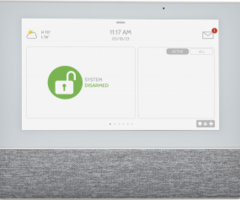
The home screen is divided into three sections. The header shows the date & time, today’s weather (Wi-Fi enrollment
only), message center and the Settings tray. The Primary interface shows arming options and sensor status & partition
select. The footer shows panic options and additional pages.
QOLSYS CONFIDENTIAL AND PROPRIETARY
PAGE
OF
13
42
Page
Indication and
Emergency
HOME SCREEN OVERVIEW The header contains the the pull down settings tray, the weather icon (Wi-Fi enrollment only), time/date and
a message icon in the upper right portion of the screen where you will find Security Provider messages and
contact info, alerts, video tutorials and FAQ’s
USER INTERFACE
QOLSYS CONFIDENTIAL AND PROPRIETARY
PAGE
OF
14
42
MESSAGE CENTER
This is where you will find Panel Alerts/Alarms notifications
This is where you will find messages from the Security Provider.
Note: This is only available when enrolled with Wi-Fi.
This is where you will find the Security Provider’s Contact Information USER INTERFACE
SETTINGS TRAY
QOLSYS CONFIDENTIAL AND PROPRIETARY
PAGE
OF
15
42
To access the Settings tray swipe down on the bar at the top of the screen. The
Settings tray has quick access to system, battery, PowerG signal strength & Wi-Fi status
as well as volume control, brightness and other quick settings.
Swipe down
for access
FIND IT
When partitions are
DISABLED, a Status
icon resides in the
upper left corner of
the settings tray.
Touch this icon to
return to the security
page. PROGRAMMING The Settings page allows quick access to various simple
features & settings.
PROGRAMMING
FIND IT
Swipe down
for access
SETTINGS
SETTINGS
Setting
Description
Display
Adjust brightness, font size & 12/24 hour time
About
Displays software, battery, Wi-Fi, Panel and PowerG information
Master Reset
Restores remote to factory settings and erases all content. Only appears
with dealer code (2222)
Wi-Fi
Connect to Wi-Fi
PowerG Upgrade
Update IQ Remote PowerG software (PowerG enrollment only)
PowerG Remote Settings
Configuration to enable or disable Power Management (PowerG
enrollment only)
Network Test
Checks the Wi-Fi signal strength (Wi-Fi enrollment only)
ENTER CODE (1111, 2222) CUSTOMIZATION
To connect to a Wi-Fi network, follow
the steps below:
Touch Settings
(Installer Code)
Then touch “Wi-Fi”
Available networks appear in a list. Touch the
desired network and use the keyboard to type
the password (if required)
QOLSYS CONFIDENTIAL AND PROPRIETARY
PAGE
OF
18
42
Enable Wi-Fi if not already active
Swipe down from the top menu bar
and select settings.
CONNECTING TO WI-FI
FIND IT
WI-FI
Swipe down
for access
SETTINGS
ENTER CODE (1111, 2222) CUSTOMIZATION
TODAY’S FORECAST
Today’s forecast is displayed on the weather icon with a graphical
representation of precipitation and High and Low temps.
LOCATION
Weather reporting is based on
location as indicated by the zip
code entered into Alarm.com
when the account is created.
4-DAY FORECAST
Touch the weather icon to get a
4-day forecast. This information
is updated once daily
via
Alarm.com services.
(Will not
display or update weather connected to
wifi only)
QOLSYS CONFIDENTIAL AND PROPRIETARY
PAGE
OF
19
42
WEATHER
FIND IT
Touch the weather icon in the
upper left corner of the header to
reveal a 4 day forecast
Note: This feature is only available during Wi-Fi enrollment. CUSTOMIZATION
PHOTO FRAME
The IQ Remote PowerG can be set to display digital photos when not in use.
This feature, called “Photo Frame”, can be changed or turned off through
“Photo Frame Settings”.
(Swipe down from the menu bar)
.
Display type
Choose a display
type for your photo
frame. Opt to turn it
off completely, scroll
through pre loaded
images or view a
“weather clock” (Wi-
Fi enrollment only)
QOLSYS CONFIDENTIAL AND PROPRIETARY
PAGE
OF
20
42
PHOTO FRAME
FIND IT
Swipe down
for access
PHOTO FRAME CUSTOMIZATION
QOLSYS CONFIDENTIAL AND PROPRIETARY
PAGE
OF
21
42
PLAY:
Starts Photo Frame immediately. Good for testing photo frame
feature appearance and transitions
REMOVE PHOTOS:
Allows you to remove photos one by one or all at
once
SETTINGS:
Change the Photo Frame’s “Display Type” from Off to On or
enable a “Weather Clock” screen saver. Change transitions, adjust
display time, set automatic on/off times and more
PHOTO FRAME APP BUTTONS
FIND IT
Swipe down
for access
PHOTO FRAME CUSTOMIZATION
PHOTO FRAME SETTINGS
FIND IT
PHOTO FRAME SETTINGS
PHOTO FRAME
Swipe down
for access
Item
Default
Description
Duration
1 minute
How long each image will show before transitioning to the next image in
the library (1, 2, or 5 minutes)
Effect
Dissolve
Transition effect used between each image (fade to black, dissolve)
Shuffle
Enabled
Display pictures in random or sequential order
Display Type
Photo Frame
Choose what to display on the screen when the panel is not in use. (Off,
Photo Frame and Weather Clock)
Photo Frame
Start Time
10 minutes
Choose the amount of time to wait after the last touch before starting the
selected display type. (1, 5, 10, 15, 20, 25, or 30 minutes)
Nighttime Mode
Start Time
11:00 PM
Determines the time when the display, voices or chimes shutdown
completely. (Use this feature to turn off the LCD, voices and/or chimes at
night)
Nighttime Mode
End Time
6:00 AM
Determines the time when the display, voices or chimes “wake up" after
sleeping. (Use this feature to turn the LCD, voices and/or chimes back on
in the morning)
Nighttime Mode
Settings
Display
Choose what the Nighttime Mode Start/End times have the ability to
control (Display, Voices and/or Chimes) MAINTENANCE MAINTENANCE
Upgrade Software
Upgrade the software version using PowerG.
UPGRADE SOFTWARE
FIND IT
Swipe down
for access
SETTINGS
ENTER CODE (1111, 2222)
NOTE:
Proper maintenance requires prompt administration of any software updates
QOLSYS CONFIDENTIAL AND PROPRIETARY
PAGE
OF
24
42
To perform a software update, follow the steps below:
1.
From the drop down menu select “Settings” and enter access code (Installer/Dealer
Code).
2.
Touch “PowerG Upgrade”
3.
A pop up message will appear asking if you want to start update for IQ Remote PowerG.
4.
Press “Start”. If a software update is available the remote will automatically begin
downloading it.
5.
Once the download is complete, the IQ Remote PowerG will restart to install the
update.
Note
: This is only valid for PowerG enrollment. Software update is automatic upon
enrollment for Wi-Fi enrollment.
Note:
For UL/cUL installations, remote software uploading is not allowed.
Wi-Fi does not need to be
manually activated on IQ
Remote PowerG in order to
update the remote
POWERG UPGRADE MAINTENANCE
QOLSYS CONFIDENTIAL AND PROPRIETARY
PAGE
OF
25
42
BATTERY REPLACEMENT
1.
Power down panel:
Press and hold the power
button on the side of the IQ Remote PowerG
for 2 seconds and select "Power Down" from
the pop up
2.
Remove Battery Door:
Remove the panel
from the backplate or table stand and then
use a small screwdriver to remove the plastic
door covering the battery.
3.
Remove Battery:
Pull the fabric tab that is
located under the battery to remove it from
the panel.
4.
Install New Battery:
Install the new battery
paying careful attention to polarity and being
sure to place the fabric pull tab under the
battery to make future removal easier.
Re-install Battery Door and screw, then re-
mount to backplate or table stand.
2
CAUTION: Do
NOT
use a screwdriver or anything sharp that could puncture the battery.
Battery
3 TROUBLESHOOTING TROUBLESHOOTING
QOLSYS CONFIDENTIAL AND PROPRIETARY
PAGE
OF
27
42
ABOUT
FIND IT
Swipe down
for access
SETTINGS
ENTER CODE (1111, 2222)
ABOUT TROUBLESHOOTING
ABOUT
QOLSYS CONFIDENTIAL AND PROPRIETARY
PAGE
OF
28
42
Item
Battery
Battery Status: Disconnected, Charging, Full
Battery Level: Displayed in %
Software
Software Version: Current Software Version
Build Number:
LInux Version:
Android Version:
Panel
MAC Address:
Panel Up Time:
PowerG*
Radio Software Version
Device Network Status
Device Radio Frequency
Sensor ID
Wi-Fi Information
Connection: Connected/Disconnected
IP Address: Panel’s IP Address when connected
SSID: Network panel is connected to
Speed: Connection speed shown in Mbps
Internal Storage
Total Space: Total space shown in GB
Photos: Breakdown of space used for photos
Videos: Breakdown of space used for videos Logs: Space
used for storing panel logs
Description
*Shown during PowerG enrollment only, TROUBLESHOOTING
DO NOT remove all power without following the steps below. In the event of needing
to move the panel from one location to another it is safe to unplug the power supply
while leaving the battery plugged in.
1.
Press and hold the power button for 2 seconds until a popup message appears on
the screen.
2.
Select “Power Down”.
3.
A popup message will appear to confirm that remote will shut down. Select “OK”.
4.
Wait for 30 seconds until the IQ Remote PowerG shuts down fully.
5.
Disconnect the power.
?
QUESTIONS?
Contact us at
techsupport@qolsys.com
IMPORTANT: Failure to
perform these steps in
the proper sequence may
result in data corruption
and/or panel failure.
QOLSYS CONFIDENTIAL AND PROPRIETARY
PAGE
OF
29
42
POWER DOWN TROUBLESHOOTING
If the panel is experiencing difficulties you can often resolve it by resetting the operating system:
1.
Press and hold the power button for 2 seconds until a pop up message appears on the screen.
2.
Select “Power Reboot”.
3.
A pop up message will appear to confirm that the remote will reboot. Select “OK”.
4.
Wait for the IQ Remote PowerG to restart.
QUESTIONS?
Contact us at
techsupport@qolsys.com
IMPORTANT: Failure to follow these steps properly may
result in data corruption and/or panel failure.
QOLSYS CONFIDENTIAL AND PROPRIETARY
PAGE
OF
30
42
?
PANEL REBOOT LEGAL LEGAL
UL/cUL RESIDENTIAL FIRE & BURGLARY INSTALLATIONS
This product has been tested and found in compliance with the following standards: UL1023 Household Burglar-Alarm
System Units, UL985 Household Fire Warning System Units, ULC-S545 Residential Fire Warning Systems Control Units
and ULC-S304 Security Level I Control Units, Accessories and Receiving Equipment for Intrusion Alarm Systems. For ULC
Installations refer to the Standard for the Installation of Residential Fire Warning Systems, CAN/ULC-S540:
-
Use only the compatible power supply referenced in this Installation Manual. 24 h standby power must be provided for
fire applications and 4h for burglary only applications (AC trouble must be transmitted to SRC within 60 minutes).
-
Priority of signals on the Panel is set as Fire, CO, Burg, Panic, Aux and then Flood.
-
Use at least one compatible listed Smoke Detector for Fire Installations.
-
The entry delay shall not exceed 45 sec (UL) and 180 sec (ULC Security Level 1).
-
The exit delay shall not exceed 120 seconds (UL).
-
The control panel supports the Temporal 3 pattern for fire alarm notification
-
Test transmission cycle shall be set for 7 days transmission for Residential Fire applications, or 30 days for Residential
Burglary only applications.
-
Keypad siren is for supplementary use.
Note
:
For ULC Residential Fire and Burglary (ULC-S304 Level I) installations set for daily test transmission, Wireless
Supervision window shall be set to 4 hours for UL/ULC Residential Fire Installations. Wireless Supervision window shall be
set to 24 hours for Residential Burglary Installations only. RF Jam detection shall be enabled.
For UL 985 6th Ed. Compliant installations using also the Wi-Fi connection, ensure Power for network equipment such as
hubs, switches, routers, servers, modems, etc., is backed up or powered by an uninterruptible power supply (UPS), standby
battery or the control unit, capable of facilitating 24 h standby. LEGAL
UL/ULC COMMERCIAL BURGLARY INSTALLATIONS
This product has been tested and found in compliance with the following standards: UL2610 Central Station Burglar-Alarm
Units and ULC-S304 Control Units, Accessories and Receiving Equipment for Intrusion Alarm Systems, Security Levels I-II.
The subscriber control unit shall provide for the connection of protective wiring, conductors, and attachments in accordance
with the Standard for Installation and Classification of Burglar and Holdup Alarm Systems, UL 681 in USA and in accordance
with ULC-S301, CSA C22.1, Canadian Electrical Code, Part I, Safety Standard for Electrical Installations and ULC-S302
Standard for the Installation, Inspection and Testing of Intrusion Alarm Systems, in Canada.
Note: The product is not intended for installation outdoors or outside the protected premises.
This product is UL/ULC listed under the following categories: AMQE/AMCX7 Central Stations Alarm Units, UTOU/UTOU7
Control Units and Accessories, Household System Type NBSX/NBSX7 Household Burglar Alarm System Units. For further
information on this product’s listings please also refer to the official listing guides published at the UL website (www.ul.com)
under Online Directory Section.
Programming:
The notes in the Installation Manual describing the system configurations for UL/uLC listed installations shall be
implemented. RJ Jam detection shall be enabled. Panel Siren is for supplementary use.
Use only PowerG sensors listed in “Supported PowerG Sensors” on page 176 of this installer manual for UL/ULC
Commercial Burglary installations. Hardwire input zones cannot be used in UL/ULC Commercial Burg installations.
Partitions have not been evaluated for UL/ULC Commercial Burg installations. Require valid user code to arm this system
must be enabled.
LEGAL
UL2610 Central Station with Standard or Encrypted Line Security Service and ULC-S304 Security Level I-II/A3 Active
communication channel:
-
The installation must use the integral cellular communicator, which sends events over Cellular Data Network to the
compatible Sur-Gard System I/II/III/IV/5 receiver.
-
The communication path supervision window is set to 180s with 90s heartbeat and the compromise detection takes
place within 3 minutes. The panel is using encrypted line security AES256. NIST certificate A1552.
-
Wireless Supervision window shall be enabled and set to 4hours
-
Open/Closing acknowledgment shall be enabled
-
For ULC-S304 compliant installations using also the Wi-Fi connection, ensure Power for network equipment such as
hubs, switches, routers, servers, modems, etc., is backed up or powered by an uninterruptible power supply (UPS),
standby battery or the control unit, capable of facilitating 24 h standby.
-
The entry delay shall not exceed 60s (UL) and 60s (ULC Security Level II).
-
The exit delay shall not exceed 60s (UL) and 45s (ULC Security Level II).
Note: For UL certified Commercial Burglary Central Station applications the IQ Remote PowerG provides an
acknowledgment signal to the user interface to confirm that normal closing signal has been received once the system has
been armed. The device causes an audible and visual indication, when it receives the acknowledgment signal transmitted
from the monitoring station compatible receiver: “Panel- Arming Response from Central Station is Acknowledged”
UL/ULC COMMERCIAL BURGLARY INSTALLATIONS continued...
QOLSYS CONFIDENTIAL AND PROPRIETARY
PAGE
OF
34
42 LEGAL
Protection of the Control Unit:
The local control unit and the local power supply must be protected in one of the following ways:
-
The control unit and audible alarm device must be in a protected area which is armed 24 hours a day.
-
Each partition must arm the area protecting the control unit and the audible alarm device power supply. This may
require duplicate protection armed by each partition. Access to this protected area, without causing an alarm, will
require that all partitions be disarmed.
-
In all cases described above, the protected area for the control unit must be programmed as not-bypassable
For installations employing packet switched (network) communications such as Cellular/Wi-Fi the following
recommendations shall be followed:
-
Select the Internet Service Providers that have redundant servers/systems and Back-up power.
-
Routers shall have Firewalls enabled and methods to identify and protect against “Denial of Service” attacks (i.e. via
“spoofing”).
For UL Commercial Burglary applications the loss of communication with the monitoring station shall be treated as an alarm
condition by monitoring station personnel when the burglar alarm system is in the armed state, and as a trouble condition
while the system is disarmed. Packet switched data network (PSDN) interface equipment, manufactured by other than the
burglar alarm equipment manufacturer, that is not provided with the burglar alarm system and/or not required for the
processing of the signals shall be evaluated to the applicable requirements of the Standard for Information Technology
Equipment - Safety - Part 1: General Requirements, UL 60950-1, or the Standard for Audio/Video, Information and
Communication Technology Equipment - Part 1: Safety Requirements, UL 62368-1, as communication equipment. Any
network interface device which adds value or manipulates the original data packet such as changing transmissions formats,
adding encryption, and the like, shall comply with the applicable requirements noted in this standard.
UL/ULC COMMERCIAL BURGLARY INSTALLATIONS continued... LEGAL
User Information:
-
The installer should advise the user and note in the User’s Manual
-
Service organization name and telephone number
-
The programmed exit and entry time
-
Instructions to test system weekly
-
Note that the installer code cannot arm or disarm the system
-
The installer should caution the user not to give system information (e.g., codes, bypass methods, etc.) to
casual users (e.g., service people) and to only give out codes set to expire within 24 hours
-
Identification of the conditions that might be expected to result in false alarms or impaired operation of the
product(s): arming the system and not respecting the exit delay, entering the protected premises and not
respecting the entry delay for disarming the system can cause false alarms.
QOLSYS CONFIDENTIAL AND PROPRIETARY
PAGE
OF
36
42
UL/ULC COMMERCIAL BURGLARY INSTALLATIONS continued... LEGAL
FCC & ISED CANADA COMPLIANCE STATEMENT
This Class [B] digital apparatus meets all requirements of the Canadian Interference
-
Causing Equipment
Regulations.
Cet appareil numérique de la classe [B] respecte toutes les exigences du Réglement sur le matériel brouilleur du
Canada.
IMPORTANT!
Changes or modifications not expressly approved by Qolsys Inc. could void the user’s authority to
operate the equipment.
CAUTION!
This equipment complies with radiation exposure limits set forth for uncontrolled environment. The
antenna(s) used for this transmitters must be installed to provide a separation distance of at least 20 cm from all
persons and must not be collocated or operating in conjunction with any other antenna or transmitter.
This device complies with Part 15 of the FCC Rules. Operation is subject to the following two conditions: (1) this
device may not cause harmful interference, and (2) this device must accept any interference received, including
interference that may cause undesired operation.
QOLSYS CONFIDENTIAL AND PROPRIETARY
PAGE
OF
37
42 LEGAL
This equipment has been tested and found to comply with the limits for a Class B digital device, pursuant to part
15 of the FCC Rules. These limits are designed to provide reasonable protection against harmful interference in a
residential installation. This equipment generates, uses and can radiate radio frequency energy and, if not
installed and used in accordance with the instructions, may cause harmful interference to radio communications.
However, there is no guarantee that interference will not occur in a particular installation. If this equipment does
cause harmful interference to radio or television reception, which can be determined by turning the equipment
off and on, the user is encouraged to try to correct the interference by one or more of the following measures:
—Reorient or relocate the receiving antenna.
—Increase the separation between the equipment and receiver.
—Connect the equipment into an outlet on a circuit different from that to which the receiver is connected.
—Consult the dealer or an experienced radio/TV technician for help
.
QOLSYS CONFIDENTIAL AND PROPRIETARY
PAGE
OF
38
42
FCC & ISED CANADA COMPLIANCE STATEMENT continued... SPECIFICATIONS SPECIFICATIONS
Items
Parameters
IQ Remote PowerG
Platform
Android OS
Android 7.1
LCD Display
Size
7” LCD
Resolution
1024 x 600
RG
24bit
Touchscreen
Type
Capacitive glass multi-touch
User Codes
Up to 242
Role based (Dealer, Installer, Master, User, Guest, Duress)
Wireless
Security R/F
PowerG 912- 915MHz. Up to 128 RF Zones
WiFi
Wi-Fi 802.11 b/g/n/ac dual band 2.4/5ghz
Flash Memory
Internal Storage
16GB
QOLSYS CONFIDENTIAL AND PROPRIETARY
PAGE
OF
40
42 Items
Parameters
IQ Remote PowerG
LED Indicator
Status LED
Disabled
Speaker
Mono 1W
Microphone
Microphone
x 2 microphone
Siren
SPL minimum 85dB for UL985
Tamper
Tamper Switch
Wall and Enclosure Tamper
Battery
Type
Lithium Polymer 2600mAh. Guangzhou Great Power Energy & Technology CO LTD. Model ICR 18650
Buttons
Standby
Right side button used for sleep/wake, and clean screen cancel, panel power down, panel reboot
Mechanical
Dimension
6.1”H x 7.7”W x 1”D (155mm x 195mm x 27mm)
Power Supply
AC/DC External Plug-in
Adapter
Output: 12v 1000mA CC, Input 100-240VAC 50/60Hz. Adapter evaluated at 120vAC for UL/cUL.
Sheznzhen Sure-Power Electrical CO LTD. Model SW-120100
Mount
Back Plate
Wall mount or table top stand (optional)
Certification
UL/cUL/ULC
UL/cUL Residential Fire and Burglary and UL/ULC Commercial Burglary Alarm Control Unit. Compliant
with standards: UL985, UL1023, UL2610, ULC-S545, ULC-S304
FCC/IC
2AAJXQS-IQRTPG/11205A-QSIQRTPG
Temperature
Operational
0 to 40C, up to 93% relative humidity, indoor, dry ordinary locations use only
Storage
-20 to 60C
SPECIFICATIONS Document#: IQRPG-IM-07-22
Revision Date: 07/29/22
Qolsys Inc. proprietary.
Reproduction without permission is not permitted.
- Uploaded