Resideo IPCAM-WOC2 - Quick Install Guide - Dated 03/21 Rev. C
Related Products
Related Categories
- Security Cameras
- HD Security Cameras
- Wireless Security Cameras
- Security Cameras
- Outdoor Cameras
- Low-Light Security Cameras
- HD Security Cameras
- 1080P Security Cameras
Document Transcript
Google Play and the Google Play logo are trademarks
of Google Inc.
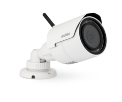
IPCAM-WOC2
HD Wi-Fi Outdoor Video Camera
Quick Installation Guide
IPCAM-WOC2 is a 1080p, full HD Wi-Fi
®
video camera intended for outdoor use with Resideo
Total Connect® 2.0.
•
Camera setup requires a Total Connect® 2.0 account
and the Total Connect 2.0 mobile app.
Video Services
must be enabled in AlarmNet 360™.
•
Camera operation requires minimum available bandwid
th of 2.1 Mbps.
Package Contents
A. Camera
B. Sun shield
C. Power cable extension [8’ cable]
D. Power adapter with 7’ cable
E. Pig-tail power cable
F. Screws and Allen wrench
G. Antenna
a. Reset switch
b. Microphone Jack
c. Power
Planning Configuration and Installation
See the other side of this sheet for more about mou
nting at the installation site
•
The camera should be situated within
200 feet
of a power outlet and within the verified range of
its Wi-Fi® connection. DO NOT mount the camera wit
hin 1
foot of any other wireless device. Depending on the
specifics of your installation, a range extender m
ay be needed to ensure adequate Wi-Fi signal streng
th.
•
Pre-installation: It is strongly recommended that c
amera configuration be done as close as possible to
the Wi-Fi router with which the camera will be lin
ked.
After setup, use a third-party app to check signal
strength at the installation site before mounting (
over for more information on signal strength.)
•
The power adapter must be connected to a non-switch
able power outlet.
•
Direct sunlight on the camera lens / image sensor m
ay affect picture quality. When placing the camera,
consider how the lighting can vary with time of da
y
and other conditions. The included sun shield can b
e attached to the camera to help minimize problems
with sun glare.
IMPORTANT
: Use only ONE of the included power extension cabl
es. This cable adds
8 feet
to the supplied power adapter for a total of
15 feet
. Alternately, you may
use the pig-tail power cable to extend the power ad
apter cable with a maximum of
200 feet
of
18 AWG
wire.
If the included extension cable is
not used
, you may cut and splice (observing good workmanshi
p) the power transformer cable.
Ensure proper polarity if the pig-tail power cable
is used. The pig-tail’s black (negative) wire must
be connected to the negative (white
dashed) wire on the power adapter.
Wi-Fi Configuration and Camera Registration
Download the Total Connect® 2.0 app from the App St
ore or on Google Play.
(Look for the red Total Connect 2.0 logo.)
Note
: Significant differences between the
iOS and Android versions of the app are noted in th
ese instructions.
For best results, configure only one camera at a ti
me.
Check these settings when you turn on your mobile d
evice’s Wi-Fi and Bluetooth:
•
Make sure the Bluetooth isn’t connected to another
device, such as headphones
•
Also, make sure the mobile device
is NOT on Silent
(ringer and speaker should be audible)
a. Verify that the camera’s antenna is securely con
nected.
b. Turn on your smart device’s Bluetooth and Wi-Fi.
c. Launch the app and sign in with your Total Conne
ct® 2.0 account.
d. Plug the power supply into an AC outlet,
but:
.
DON’T CONNECT THE POWER SUPPLY TO THE CAMERA YET!
When you do,
refer to the diagram at right
→
→→
→
If your account has more than one
Location
, select the appropriate one using the
dropdown
menu at the top of the screen.
Press
CAMERAS
at the bottom (iOS) or top (Android) of the screen.
(Remember that the
horizontal Navigation Order can be customized in iO
S.)
a. At upper right, press
ADD CAMERA
(iOS) or
(Android)
b. Select the type of camera you’re installing. The
names of the camera models may
vary from the illustration at right.
c. Name the camera and press
NEXT
.
d. Connect the power supply to the camera. The LED
at the top flashes various colors. Then,
WAIT
for the camera’s LED to flash blue
only
. This may take a couple of minutes.
e. Press
NEXT
on the app.
a. On the
Pair Your Camera
screen, press
Generate QR Code
. After a brief wait, the
code appears.
b. Show the QR code on your device to the camera fr
om 3 – 8 inches away.
If you can, keep an eye on your device’s screen; wh
en the code is scanned
successfully, a confirmation message will appear ov
er the QR code.
The app will also provide audible confirmation via
your mobile device’s speaker.
c. Select your Wi-Fi network and press
NEXT
.
d. Enter the network password and press
NEXT
. Final setup begins.
When setup is complete, the LED on the camera chang
es from steady blue, to purple
and finally to steady green.
The app also displays
Setup Successful
*. Press
DONE
or
ADD ANOTHER CAMERA
.
After setup, go back to the
CAMERAS
page and check your newly-registered camera.
Touch the
preview image
to launch a live stream from the camera.
*The app will tell you if you need to repeat the se
tup process. This involves resetting the
camera, which is described in the app itself.
See the other side of this sheet for more informati
on about the required steps.
WOC2
Privacy
WOC2 Resetting the Camera
If setup needs to be repeated, or to connect the ca
mera to a different network, activate the Reset swi
tch.
•
To
reset
the connection, press and hold the reset button unt
il the LED on the camera starts blinking white. Rel
ease the button immediately after the LED
starts blinking.
•
To
join a new/different
network:
o
On the app’s
Cameras
screen, press and delete the camera from the li
nk on its
settings
page.
o
Press and hold the
Reset
switch to reset all settings to their factory defa
ults
o
Unplug the camera and then reconnect it.
o
Repeat the registration procedure.
LED STATUS INDICATOR
During installation
Blue, blinking
Power on. Ready to start setup.
Blue, steady
Connected to the app. Ready to comple
te setup.
Purple, steady
QR code scan is complete. Restart t
he Wi-Fi connection process.
Green, blinking
Connecting to Wi-Fi network.
Red, steady
Setup timed out. Unplug the camera, pl
ug it back in and restart setup process.
During operation
Green, blinking
Connecting to Wi-Fi network.
Green, steady
Connected to Wi-Fi and operating. Note: The camera
is always ready to record but only originates live
streaming video when called for by
the app.
Red, blinking
Not connected to Wi-Fi.
Low-light operation is indicated by four red LEDs a
rranged around the lens on the front of the camera.
More about mounting at the installation site
IPCAM-WOC2 can be wall- or ceiling-mounted. The cam
era can be installed with cables running along the
outside of a wall, or inside the wall. For outdoor
installations where cables are exposed to the weath
er, please protect the cable-ends with an enclosure
such as a weatherproof single-gang box, available
at most
hardware stores. In any installation, make sure the
camera’s antenna is firmly connected.
Checking Wi-Fi signal strength at the site using th
e app:
•
On the
Cameras
page, touch
for
the camera you’re setting up
(on
Android
, touch )
•
Select
Camera Information >
•
Signal Strength
is displayed under
“IP Address”
o
60 – 100 Optimal
o
40 – 59 Marginal
o
0
0
– 39 Use of a Wi-Fi range
extender strongly
recommended
Wall mount example
Ceiling mount example
(both shown with weatherproof single-gang box)
FEDERAL COMMUNICATIONS COMMISSION & ISED STATEMENTS
The user shall not make any changes or modification
s to the equipment unless authorized by the Install
ation Instructions or User's Manual. Unauthorized c
hanges or modifications could void
the user's authority to operate the equipment.
CLASS B DIGITAL DEVICE STATEMENT
This equipment has been tested to FCC requirements
and found to comply with the limits for a Class B d
igital device, pursuant to part 15 of the FCC Rules
. These limits are designed to
provide reasonable protection against harmful inter
ference in a residential installation. This equipme
nt generates uses and can radiate radio frequency e
nergy and, if not installed and used in
accordance with the instructions, may cause harmful
interference to radio communications. However, the
re is no guarantee that interference will not occur
in a particular installation. If this
equipment does cause harmful interference to radio
or television reception, which can be determined by
turning the equipment off and on, the user is enco
uraged to try to correct the
interference by one or more of the following measur
es:
•
If using an indoor antenna, have a quality outdoor
antenna installed.
•
Reorient or relocate the receiving antenna.
•
Move the radio or television receiver away from th
e receiver/control.
•
Increase the separation between the equipment and
receiver.
•
Connect the equipment into an outlet on a circuit
different from that to which the receiver is connec
ted.
•
Consult the dealer or an experienced radio/TV tech
nician for help.
FCC / ISED STATEMENT
This device complies with Part 15 of the FCC Rules,
and ISED’s license-exempt RSSs. Operation is subje
ct to the following two conditions: (1) This device
may not cause harmful interference,
and (2) This device must accept any interference re
ceived, including interference that may cause undes
ired operation.
Cet appareil est conforme à la partie 15 des règles
de la FCC et exempt de licence RSS d’ISED. Son fon
ctionnement est soumis aux conditions suivantes: (1
) Cet appareil ne doit pas causer
d’interférences nuisibles. (2) Cet appareil doit ac
cepter toute interférence reçue y compris les inter
férences causant une réception indésirable.
This radio transmitter (IC: 573F-IPCAMWOC2) has bee
n approved by Innovation, Science and Economic Deve
lopment Canada to operate with the antenna types li
sted below, with the
maximum permissible gain indicated. Antenna types n
ot included in this list that have a gain greater t
han the maximum gain indicated for any type listed
are strictly prohibited for use with this
device.
Le présent émetteur radio (IC: 573F-IPCAMWOC2) a ét
é approuvé par Innovation, Sciences et Développemen
t économique Canada pour fonctionner avec les types
d'antenne énumérés ci-
dessous et ayant un gain admissible maximal. Les ty
pes d'antenne non inclus dans cette liste, et dont
le gain est supérieur au gain maximal indiqué pour
tout type figurant sur la liste, sont
strictement interdits pour l'exploitation de l'émet
teur.
Antenna Type /
Type d'antenne
Model Number /
Numéro de modèle
Antenna Gain /
gain de l'antenne
Support /
Support
Dipole
98865MRSX004
2 dB
2.4GHz+BT
Note
For product available in the USA/Canada market, onl
y channel 1~11 can be operated. Selection of
other channels is not possible.
Pour les produits disponibles aux États-Unis / Cana
da du marché, seul le canal 1 à 11 peuvent
être exploités. Sélection d'autres canaux n'est pas
possible.
RF EXPOSURE STATEMENT:
The antenna(s) used for this device must be install
ed to provide a separation distance of at least 7.8
inches (20 cm) from all persons and must not be co
-located or operating in conjunction
with any other antenna or transmitter except in acc
ordance with FCC and ISED multi-transmitter product
procedures.
MISE EN GARDE EXPOSITION AUX FRÉQUENCES RADIO:
La/les antenne(s) utilisée(s) pour cet émetteur doi
t/doivent être installée(s) à une distance de sépar
ation d'au moins 20 cm (7,8 pouces) de toute person
ne et ne pas être située(s) ni
fonctionner parallèlement à tout autre transmetteur
ou antenne, excepté en conformité avec les procédu
res de produit multi transmetteur FCC et ISED.
DECLARACIÓN IFETEL
La operación de este equipo está sujeta a las sigui
entes dos condiciones
1. Es posible que este equipo o dispositivo no caus
e interferencia perjudicial y
2.
Este equipo debe aceptar cualquier interferencia, i
ncluyendo la que pueda causar su operación
no deseada.
DECLARACIÓN ANATEL
Este equipamento opera emcarátersecundário, isto é,
nãotemdireito a proteção contra interferência
prejudicial, mesmo de estações do mesmotipo, e nãop
odecausarinterferência a sistemas operando
emcaráterprimário.
For the latest documentation, support and warranty
information, please go to:
www.resideo.com
This product manufactured by Resideo Technologies,
Inc. and its affiliates
R800-26818C 3/21 Rev C
2 Corporate Center Drive, Suite 100
P.O. Box 9040, Melville, NY 11747
2021 Resideo Technologies, Inc.
www.resideo.com
- Uploaded