2GIG GC3/GC3e - Installation and Program Guide Rev B
Related Products

Related Categories
Document Transcript
2GIG
®
GC3/GC3e Security & Automation System
Installation and Programming Guide
10023748 B
WARNING: OWNER’S INSTRUCTION NOTICE
Not to be removed by anyone except occupant Copyright © 2019 Nortek Security & Control LLC
2
Copyright © 2019 Nortek Security & Control LLC. All Rights Reserved. U.S. Patent D727,857. Australian Patent No. 357098. Additi
onal Patents Pending.
The 2GIG, GC3, GC3e, GoControl, and Linear logos are registered trademarks of Nortek Security & Control LLC in the United State
s and/or other countries. Other Nortek
Security & Control trademarks may also appear in these materials. Other names or brands may be claimed as the property of other
s. For more information, contact your
2GIG alarm dealer for pricing or visit
www.nortek.com
,
www.nortekcontrol.com
, or
www.2gig.com
.
This document utilizes the Cue gestural icon system by P.J. Onori, which is available under a Creative Commons Attribution-Shar
eAlike 3.0 United States (CC-BY-SA-3.0)
license.
Information in this document is subject to change without notice. The availability of particular products, services, and featur
es may vary by region. Please check with your
local dealer for further details and availability of language options.
No part of this publication may be reproduced, stored in a retrieval system, or transmitted in any form or any means electronic
or mechanical, including photocopying and
recording for any purpose other than the purchaser's personal use without the written permission of Nortek Security & Control.
Nortek Security & Control
5919 Sea Otter Place, Suite 100
Carlsbad, CA 92010
USA
800-421-1587
Contents
Introduction. . . . . . . . . . . . . . . . . . . . . . . . . .
. . . . . . . . . . . . . . . . . . . . . . . . . . . . . . .
. . . . . . . . . . . . . . . . . .5
About this Guide . . . . . . . . . . . . . . . . . . . . . . .
. . . . . . . . . . . . . . . . . . . . . . . . . . . . . . .
. . . . . . . . . . . . . . . . . . . . . . . . 5
Introduction to Smart Areas™. . . . . . . . . . . . . . . . . .
. . . . . . . . . . . . . . . . . . . . . . . . . . . . . . .
. . . . . . . . . . . . . . . . . . . 5
Document Conventions. . . . . . . . . . . . . . . . . . . . . .
. . . . . . . . . . . . . . . . . . . . . . . . . . . . . . .
. . . . . . . . . . . . . . . . . . . . 6
Technical Support . . . . . . . . . . . . . . . . . . . . . .
. . . . . . . . . . . . . . . . . . . . . . . . . . . . . . . .
. . . . . . . . . . . . . . . . . . . . . . . 6
Planning the Installation . . . . . . . . . . . . . . . . . .
. . . . . . . . . . . . . . . . . . . . . . . . . . . . . . . .
. . . . . . . . . . . . . .7
System Features and Capabilities . . . . . . . . . . . . . . .
. . . . . . . . . . . . . . . . . . . . . . . . . . . . . . .
. . . . . . . . . . . . . . . . . . 7
Internal Components. . . . . . . . . . . . . . . . . . . . . .
. . . . . . . . . . . . . . . . . . . . . . . . . . . . . . . .
. . . . . . . . . . . . . . . . . . . . . 9
Additional Accessories . . . . . . . . . . . . . . . . . . . .
. . . . . . . . . . . . . . . . . . . . . . . . . . . . . . .
. . . . . . . . . . . . . . . . . . . . . . 10
Important Information . . . . . . . . . . . . . . . . . . . .
. . . . . . . . . . . . . . . . . . . . . . . . . . . . . . . .
. . . . . . . . . . . . . . . . . . . . . . 11
Create the Installation Plan. . . . . . . . . . . . . . . . . .
. . . . . . . . . . . . . . . . . . . . . . . . . . . . . . .
. . . . . . . . . . . . . . . . . . . . . 11
Installation Steps. . . . . . . . . . . . . . . . . . . . . . .
. . . . . . . . . . . . . . . . . . . . . . . . . . . . . . .
. . . . . . . . . . . . . . . . . . . . . . . . 15
Installing the System . . . . . . . . . . . . . . . . . . . . .
. . . . . . . . . . . . . . . . . . . . . . . . . . . . . . .
. . . . . . . . . . . . . . .16
Install the GC3 Cellular Radio Module . . . . . . . . . . . .
. . . . . . . . . . . . . . . . . . . . . . . . . . . . . . . .
. . . . . . . . . . . . . . . . . 16
Install/Replace the Cellular Radio Module . . . . . . . . . .
. . . . . . . . . . . . . . . . . . . . . . . . . . . . . . . .
. . . . . . . . . . . . . . . . 16
Mount the GC3 Panel’s Backplate . . . . . . . . . . . . . . .
. . . . . . . . . . . . . . . . . . . . . . . . . . . . . . . .
. . . . . . . . . . . . . . . . . 21
Connect an External Alarm Sounder. . . . . . . . . . . . . . .
. . . . . . . . . . . . . . . . . . . . . . . . . . . . . . . .
. . . . . . . . . . . . . . . . 23
Connect the Hardwire Loops. . . . . . . . . . . . . . . . . . .
. . . . . . . . . . . . . . . . . . . . . . . . . . . . . . .
. . . . . . . . . . . . . . . . . . . 24
Connect the Power Wires . . . . . . . . . . . . . . . . . . . .
. . . . . . . . . . . . . . . . . . . . . . . . . . . . . . . .
. . . . . . . . . . . . . . . . . . . 25
Control Panel Wiring Diagram. . . . . . . . . . . . . . . . . .
. . . . . . . . . . . . . . . . . . . . . . . . . . . . . . .
. . . . . . . . . . . . . . . . . . . 27
Terminal Blocks Wiring Diagram. . . . . . . . . . . . . . . . .
. . . . . . . . . . . . . . . . . . . . . . . . . . . . . . .
. . . . . . . . . . . . . . . . . . 28
Connect the Backup Battery . . . . . . . . . . . . . . . . . . .
. . . . . . . . . . . . . . . . . . . . . . . . . . . . . . .
. . . . . . . . . . . . . . . . . . . 29
Hang the GC3 Panel. . . . . . . . . . . . . . . . . . . . . . .
. . . . . . . . . . . . . . . . . . . . . . . . . . . . . . .
. . . . . . . . . . . . . . . . . . . . . 29
Ethernet Module Installation (Optional). . . . . . . . . . . .
. . . . . . . . . . . . . . . . . . . . . . . . . . . . . . . .
. . . . . . . . . . . . . . . . . 29
Install the Retaining Wall Bracket and Connect the AC Power Sup
ply. . . . . . . . . . . . . . . . . . . . . . . . . . . . . .
. . . . . . . 30
Update the GC3 Panel Firmware . . . . . . . . . . . . . . . .
. . . . . . . . . . . . . . . . . . . . . . . . . . . . . . . .
. . . . . . . . . . . . . . . . . 31
Navigate to the Installer Toolbox. . . . . . . . . . . . . . .
. . . . . . . . . . . . . . . . . . . . . . . . . . . . . . . .
. . . . . . . . . . . . . . . . . . . 32
Broadband. . . . . . . . . . . . . . . . . . . . . . . . . . .
. . . . . . . . . . . . . . . . . . . . . . . . . . . . . . . .
. . . . . . . . . . . . . . . . . . . . . . . . 32
Attaching to a Wireless Network. . . . . . . . . . . . . . . .
. . . . . . . . . . . . . . . . . . . . . . . . . . . . . . . .
. . . . . . . . . . . . . . . . . . 33
Selection Buttons . . . . . . . . . . . . . . . . . . . . . .
. . . . . . . . . . . . . . . . . . . . . . . . . . . . . . . .
. . . . . . . . . . . . . . . . . . . . . . . 33
Wired (Ethernet) . . . . . . . . . . . . . . . . . . . . . . .
. . . . . . . . . . . . . . . . . . . . . . . . . . . . . . . .
. . . . . . . . . . . . . . . . . . . . . . . 34
Programming Sensors and Peripherals. . . . . . . . . . . . . .
. . . . . . . . . . . . . . . . . . . . . . . . . . . . . . . .
. . . . . .37
Navigate to the System Confi guration Menu. . . . . . . . . . .
. . . . . . . . . . . . . . . . . . . . . . . . . . . . . . . .
. . . . . . . . . . . . . . 37
Program a Wireless Zone . . . . . . . . . . . . . . . . . . . .
. . . . . . . . . . . . . . . . . . . . . . . . . . . . . . . .
. . . . . . . . . . . . . . . . . . . 37
Next Steps. . . . . . . . . . . . . . . . . . . . . . . . . . .
. . . . . . . . . . . . . . . . . . . . . . . . . . . . . . .
. . . . . . . . . . . . . . . . . . . . . . . . . 41
Program a Wired Zone . . . . . . . . . . . . . . . . . . . . .
. . . . . . . . . . . . . . . . . . . . . . . . . . . . . . .
. . . . . . . . . . . . . . . . . . . . . 42
Program a Keyfob. . . . . . . . . . . . . . . . . . . . . . . .
. . . . . . . . . . . . . . . . . . . . . . . . . . . . . . .
. . . . . . . . . . . . . . . . . . . . . . 45 Copyright © 2019 Nortek Security & Control LLC
3
Program a Keypad . . . . . . . . . . . . . . . . . . . . . . .
. . . . . . . . . . . . . . . . . . . . . . . . . . . . . . .
. . . . . . . . . . . . . . . . . . . . . . 49
Next Steps. . . . . . . . . . . . . . . . . . . . . . . . . . .
. . . . . . . . . . . . . . . . . . . . . . . . . . . . . . .
. . . . . . . . . . . . . . . . . . . . . . . . . 53
Reset a Zone, Keyfob, or Keypad to the Factory Default Settings
. . . . . . . . . . . . . . . . . . . . . . . . . . . . . . .
. . . . . . . . . 53
Panel Programming . . . . . . . . . . . . . . . . . . . . . . .
. . . . . . . . . . . . . . . . . . . . . . . . . . . . . . .
. . . . . . . . . . . . . .54
Q1: Enter installer code (4 digits) . . . . . . . . . . . . .
. . . . . . . . . . . . . . . . . . . . . . . . . . . . . . . .
. . . . . . . . . . . . . . . . . . . . 54
Q2: Lock installer programming . . . . . . . . . . . . . . . .
. . . . . . . . . . . . . . . . . . . . . . . . . . . . . . .
. . . . . . . . . . . . . . . . . . . 54
Q3: Lock default programming . . . . . . . . . . . . . . . . .
. . . . . . . . . . . . . . . . . . . . . . . . . . . . . . .
. . . . . . . . . . . . . . . . . . . 54
Q4: Exit delay, in seconds (45-120) . . . . . . . . . . . . .
. . . . . . . . . . . . . . . . . . . . . . . . . . . . . . . .
. . . . . . . . . . . . . . . . . . 54
Q5: Entry delay 1, in seconds (30-240). . . . . . . . . . . . .
. . . . . . . . . . . . . . . . . . . . . . . . . . . . . . .
. . . . . . . . . . . . . . . . . 54
Q6: Entry delay 2, in seconds (30-240). . . . . . . . . . . . .
. . . . . . . . . . . . . . . . . . . . . . . . . . . . . . .
. . . . . . . . . . . . . . . . . 55
Q7: Remote services provider. . . . . . . . . . . . . . . . . .
. . . . . . . . . . . . . . . . . . . . . . . . . . . . . . .
. . . . . . . . . . . . . . . . . . . 55
Q8: 2-way voice . . . . . . . . . . . . . . . . . . . . . . .
. . . . . . . . . . . . . . . . . . . . . . . . . . . . . . . .
. . . . . . . . . . . . . . . . . . . . . . . 55
Q9: Disable siren after two-way audio . . . . . . . . . . . .
. . . . . . . . . . . . . . . . . . . . . . . . . . . . . . . .
. . . . . . . . . . . . . . . . . 55
Q10: Police emergency key . . . . . . . . . . . . . . . . . .
. . . . . . . . . . . . . . . . . . . . . . . . . . . . . . . .
. . . . . . . . . . . . . . . . . . . 56
Q11: Fire emergency key . . . . . . . . . . . . . . . . . . . .
. . . . . . . . . . . . . . . . . . . . . . . . . . . . . . .
. . . . . . . . . . . . . . . . . . . . 56
Q12: Emergency key. . . . . . . . . . . . . . . . . . . . . . .
. . . . . . . . . . . . . . . . . . . . . . . . . . . . . . .
. . . . . . . . . . . . . . . . . . . . . 56
Q13: Quick arming . . . . . . . . . . . . . . . . . . . . . .
. . . . . . . . . . . . . . . . . . . . . . . . . . . . . . . .
. . . . . . . . . . . . . . . . . . . . . . 56
Q14: Auto stay. . . . . . . . . . . . . . . . . . . . . . . . .
. . . . . . . . . . . . . . . . . . . . . . . . . . . . . . .
. . . . . . . . . . . . . . . . . . . . . . . . 56
Q15: Exit delay restart. . . . . . . . . . . . . . . . . . . .
. . . . . . . . . . . . . . . . . . . . . . . . . . . . . . . .
. . . . . . . . . . . . . . . . . . . . . . 56
Q16: Allow quick exit. . . . . . . . . . . . . . . . . . . . .
. . . . . . . . . . . . . . . . . . . . . . . . . . . . . . . .
. . . . . . . . . . . . . . . . . . . . . . 57
Q17: Quick bypass . . . . . . . . . . . . . . . . . . . . . .
. . . . . . . . . . . . . . . . . . . . . . . . . . . . . . . .
. . . . . . . . . . . . . . . . . . . . . . 57
Q18: Alert on disarm with keyfob after alarm . . . . . . . . .
. . . . . . . . . . . . . . . . . . . . . . . . . . . . . . .
. . . . . . . . . . . . . . . . 57
Q19: Keyfob arm/disarm confi rmation. . . . . . . . . . . . . .
. . . . . . . . . . . . . . . . . . . . . . . . . . . . . . . .
. . . . . . . . . . . . . . . . 57
Q20: Keyfob/remote arming mode on system not ready. . . . . . .
. . . . . . . . . . . . . . . . . . . . . . . . . . . . . . .
. . . . . . . . . . 57
Q21: Z-Wave feature. . . . . . . . . . . . . . . . . . . . . .
. . . . . . . . . . . . . . . . . . . . . . . . . . . . . . . .
. . . . . . . . . . . . . . . . . . . . . 57
Q22: Smart Home Controls require master code . . . . . . . . .
. . . . . . . . . . . . . . . . . . . . . . . . . . . . . . .
. . . . . . . . . . . . . 57
Q24: Temperature display units. . . . . . . . . . . . . . . . .
. . . . . . . . . . . . . . . . . . . . . . . . . . . . . . .
. . . . . . . . . . . . . . . . . . . 58
Q25: Swinger shutdown count (1-6) . . . . . . . . . . . . . .
. . . . . . . . . . . . . . . . . . . . . . . . . . . . . . . .
. . . . . . . . . . . . . . . . . 58
Q26: Cross sensor zones 99-100 . . . . . . . . . . . . . . . . .
. . . . . . . . . . . . . . . . . . . . . . . . . . . . . . .
. . . . . . . . . . . . . . . . . 58
Q27: Cross sensor timeout, in seconds (10- 120). . . . . . . .
. . . . . . . . . . . . . . . . . . . . . . . . . . . . . . . .
. . . . . . . . . . . . . 58
Q28: Siren supervision time . . . . . . . . . . . . . . . . .
. . . . . . . . . . . . . . . . . . . . . . . . . . . . . . . .
. . . . . . . . . . . . . . . . . . . . 58
Q29: CS lack of usage notifi cation time, in days (0-255) . . .
. . . . . . . . . . . . . . . . . . . . . . . . . . . . . . .
. . . . . . . . . . . . . 59
Q30: Radio modem network failure time, in minutes (0-255) . .
. . . . . . . . . . . . . . . . . . . . . . . . . . . . . . . .
. . . . . . . . . . 59
Q31: Radio network failure causes trouble. . . . . . . . . . .
. . . . . . . . . . . . . . . . . . . . . . . . . . . . . . . .
. . . . . . . . . . . . . . . 59
Q32: Radio network failure reports . . . . . . . . . . . . . . .
. . . . . . . . . . . . . . . . . . . . . . . . . . . . . . .
. . . . . . . . . . . . . . . . . . 59
Q33: Broadband network failure time in minutes . . . . . . . .
. . . . . . . . . . . . . . . . . . . . . . . . . . . . . . .
. . . . . . . . . . . . . . 59
Q34: Broadband network failure causes trouble. . . . . . . . .
. . . . . . . . . . . . . . . . . . . . . . . . . . . . . . . .
. . . . . . . . . . . . . 59
Q35: Broadband network failure reports. . . . . . . . . . . . .
. . . . . . . . . . . . . . . . . . . . . . . . . . . . . . .
. . . . . . . . . . . . . . . . 60
Q36: Periodic test, in days (0-255) . . . . . . . . . . . . .
. . . . . . . . . . . . . . . . . . . . . . . . . . . . . . . .
. . . . . . . . . . . . . . . . . . . 60
Q37: Alarm cancel time, in minutes (5-255) . . . . . . . . . .
. . . . . . . . . . . . . . . . . . . . . . . . . . . . . . .
. . . . . . . . . . . . . . . . 60
Q38: Alarm cancel display. . . . . . . . . . . . . . . . . . .
. . . . . . . . . . . . . . . . . . . . . . . . . . . . . . . .
. . . . . . . . . . . . . . . . . . . . 60
Q39: Alarm abort window transmission delay. . . . . . . . . . .
. . . . . . . . . . . . . . . . . . . . . . . . . . . . . . .
. . . . . . . . . . . . . . 60
Q40: Burglary bell cutoff
time . . . . . . . . . . . . . . . . . . . . . . . . . . . .
. . . . . . . . . . . . . . . . . . . . . . . . . . . . . . .
. . . . . . . . . 60
Q41: Fire bell cutoff
time. . . . . . . . . . . . . . . . . . . . . . . . . . . . .
. . . . . . . . . . . . . . . . . . . . . . . . . . . . . . .
. . . . . . . . . . . . 60
Q42: Trouble doesn’t sound at night. . . . . . . . . . . . . .
. . . . . . . . . . . . . . . . . . . . . . . . . . . . . . . .
. . . . . . . . . . . . . . . . . 61
Q43: Z-Wave siren mode . . . . . . . . . . . . . . . . . . . .
. . . . . . . . . . . . . . . . . . . . . . . . . . . . . . .
. . . . . . . . . . . . . . . . . . . . 61
Q44: Open collector #1 output . . . . . . . . . . . . . . . .
. . . . . . . . . . . . . . . . . . . . . . . . . . . . . . . .
. . . . . . . . . . . . . . . . . . . 61
Q45: Open collector #2 output . . . . . . . . . . . . . . . .
. . . . . . . . . . . . . . . . . . . . . . . . . . . . . . . .
. . . . . . . . . . . . . . . . . . . 61
Q46: Time to detect AC loss, in minutes. . . . . . . . . . . .
. . . . . . . . . . . . . . . . . . . . . . . . . . . . . . . .
. . . . . . . . . . . . . . . . 62
Q47: Random AC loss report time . . . . . . . . . . . . . . .
. . . . . . . . . . . . . . . . . . . . . . . . . . . . . . . .
. . . . . . . . . . . . . . . . . 62
Q48: Programming mode entry reports to CS. . . . . . . . . . .
. . . . . . . . . . . . . . . . . . . . . . . . . . . . . . . .
. . . . . . . . . . . . . 62 Copyright © 2019 Nortek Security & Control LLC
4
Q49: Trouble reports to CS. . . . . . . . . . . . . . . . . . .
. . . . . . . . . . . . . . . . . . . . . . . . . . . . . . .
. . . . . . . . . . . . . . . . . . . . 62
Q50: Trouble restore reports to CS. . . . . . . . . . . . . . .
. . . . . . . . . . . . . . . . . . . . . . . . . . . . . . .
. . . . . . . . . . . . . . . . . . 62
Q51: Manual bypass reports to CS. . . . . . . . . . . . . . . .
. . . . . . . . . . . . . . . . . . . . . . . . . . . . . . .
. . . . . . . . . . . . . . . . . 62
Q52: Bypass restore reports to CS. . . . . . . . . . . . . . .
. . . . . . . . . . . . . . . . . . . . . . . . . . . . . . . .
. . . . . . . . . . . . . . . . . 62
Q53: AC loss reports to CS. . . . . . . . . . . . . . . . . . .
. . . . . . . . . . . . . . . . . . . . . . . . . . . . . . .
. . . . . . . . . . . . . . . . . . . . 62
Q54: AC restore reports to CS . . . . . . . . . . . . . . . .
. . . . . . . . . . . . . . . . . . . . . . . . . . . . . . . .
. . . . . . . . . . . . . . . . . . . 63
Q55: System low battery reports to CS. . . . . . . . . . . . .
. . . . . . . . . . . . . . . . . . . . . . . . . . . . . . . .
. . . . . . . . . . . . . . . . 63
Q56: System low battery restore reports to CS. . . . . . . . .
. . . . . . . . . . . . . . . . . . . . . . . . . . . . . . . .
. . . . . . . . . . . . . . 63
Q57: RF low battery reports to CS . . . . . . . . . . . . . .
. . . . . . . . . . . . . . . . . . . . . . . . . . . . . . . .
. . . . . . . . . . . . . . . . . . 63
Q58: Sensor low battery restore reports to CS. . . . . . . . .
. . . . . . . . . . . . . . . . . . . . . . . . . . . . . . . .
. . . . . . . . . . . . . . 63
Q59: System disarmed reports to CS . . . . . . . . . . . . . . .
. . . . . . . . . . . . . . . . . . . . . . . . . . . . . . .
. . . . . . . . . . . . . . . . 63
Q60: System armed reports to CS . . . . . . . . . . . . . . .
. . . . . . . . . . . . . . . . . . . . . . . . . . . . . . . .
. . . . . . . . . . . . . . . . . 63
Q61: Alarm restore reports to CS . . . . . . . . . . . . . . .
. . . . . . . . . . . . . . . . . . . . . . . . . . . . . . .
. . . . . . . . . . . . . . . . . . . 63
Q62: Smart test reports. . . . . . . . . . . . . . . . . . . .
. . . . . . . . . . . . . . . . . . . . . . . . . . . . . . . .
. . . . . . . . . . . . . . . . . . . . . 64
Q63: RF jam causes trouble . . . . . . . . . . . . . . . . . . .
. . . . . . . . . . . . . . . . . . . . . . . . . . . . . . .
. . . . . . . . . . . . . . . . . . . 64
Q64: System tamper causes trouble. . . . . . . . . . . . . . .
. . . . . . . . . . . . . . . . . . . . . . . . . . . . . . . .
. . . . . . . . . . . . . . . . 64
Q65: Auto unbypass for manual bypass . . . . . . . . . . . . . .
. . . . . . . . . . . . . . . . . . . . . . . . . . . . . . .
. . . . . . . . . . . . . . . 64
Q66: Force bypass reports . . . . . . . . . . . . . . . . . .
. . . . . . . . . . . . . . . . . . . . . . . . . . . . . . . .
. . . . . . . . . . . . . . . . . . . . 64
Q67: Event log . . . . . . . . . . . . . . . . . . . . . . . .
. . . . . . . . . . . . . . . . . . . . . . . . . . . . . . .
. . . . . . . . . . . . . . . . . . . . . . . . 64
Q68: Allow backlight always on (demo mode) . . . . . . . . . .
. . . . . . . . . . . . . . . . . . . . . . . . . . . . . . .
. . . . . . . . . . . . . . 64
Q69: Smart Areas . . . . . . . . . . . . . . . . . . . . . . .
. . . . . . . . . . . . . . . . . . . . . . . . . . . . . . . .
. . . . . . . . . . . . . . . . . . . . . . 64
Q70: Main Panel Sounder Follows . . . . . . . . . . . . . . .
. . . . . . . . . . . . . . . . . . . . . . . . . . . . . . . .
. . . . . . . . . . . . . . . . . 65
Q71: Security pin code length. . . . . . . . . . . . . . . . .
. . . . . . . . . . . . . . . . . . . . . . . . . . . . . . . .
. . . . . . . . . . . . . . . . . . . 65
Restore the Factory Default Settings . . . . . . . . . . . . .
. . . . . . . . . . . . . . . . . . . . . . . . . . . . . . .
. . . . . . . . . . . . . . . . . . 65
System Confi
guration Reference . . . . . . . . . . . . . . . . . . . . .
. . . . . . . . . . . . . . . . . . . . . . . . . . . . . . . .
. . . .66
Sensor Programming Reference. . . . . . . . . . . . . . . . . .
. . . . . . . . . . . . . . . . . . . . . . . . . . . . . . .
. . . . . . . . . . . . . . . . . 66
Panel Programming Reference. . . . . . . . . . . . . . . . . .
. . . . . . . . . . . . . . . . . . . . . . . . . . . . . . . .
. . . . . . . . . . . . . . . . . 71
Features to Limit False Alarms . . . . . . . . . . . . . . . .
. . . . . . . . . . . . . . . . . . . . . . . . . . . . . . .
. . . . . . . . . . . . . . . . . . . . 75
Image Sensor . . . . . . . . . . . . . . . . . . . . . . . . .
. . . . . . . . . . . . . . . . . . . . . . . . . . . . . . .
. . . . . . . . . . . . . . . . . . . . . . . . 76
Smart Home Settings Menu. . . . . . . . . . . . . . . . . . . .
. . . . . . . . . . . . . . . . . . . . . . . . . . . . . . .
. . . . . . . . . . .76
Smart Home Settings Menu . . . . . . . . . . . . . . . . . . .
. . . . . . . . . . . . . . . . . . . . . . . . . . . . . . .
. . . . . . . . . . . . . . . . . . . 76
Navigate to the Smart Home Settings Menu. . . . . . . . . . . .
. . . . . . . . . . . . . . . . . . . . . . . . . . . . . . .
. . . . . . . . . . . . . . 76
Add a New Device. . . . . . . . . . . . . . . . . . . . . . . .
. . . . . . . . . . . . . . . . . . . . . . . . . . . . . . .
. . . . . . . . . . . . . . . . . . . . . . 77
Remove a Device . . . . . . . . . . . . . . . . . . . . . . .
. . . . . . . . . . . . . . . . . . . . . . . . . . . . . . . .
. . . . . . . . . . . . . . . . . . . . . . 78
Check the Network . . . . . . . . . . . . . . . . . . . . . .
. . . . . . . . . . . . . . . . . . . . . . . . . . . . . . . .
. . . . . . . . . . . . . . . . . . . . . . 79
Rediscover the Network . . . . . . . . . . . . . . . . . . . .
. . . . . . . . . . . . . . . . . . . . . . . . . . . . . . .
. . . . . . . . . . . . . . . . . . . . . 79
View All Devices . . . . . . . . . . . . . . . . . . . . . . .
. . . . . . . . . . . . . . . . . . . . . . . . . . . . . . .
. . . . . . . . . . . . . . . . . . . . . . . . 80
Associating Z-Wave Devices. . . . . . . . . . . . . . . . . . .
. . . . . . . . . . . . . . . . . . . . . . . . . . . . . . .
. . . . . . . . . . . . . . . . . . . 84
Reset the Controller . . . . . . . . . . . . . . . . . . . . .
. . . . . . . . . . . . . . . . . . . . . . . . . . . . . . .
. . . . . . . . . . . . . . . . . . . . . . . 85
Learn Controller . . . . . . . . . . . . . . . . . . . . . . .
. . . . . . . . . . . . . . . . . . . . . . . . . . . . . . .
. . . . . . . . . . . . . . . . . . . . . . . . 86
Testing the Installation. . . . . . . . . . . . . . . . . . . .
. . . . . . . . . . . . . . . . . . . . . . . . . . . . . . .
. . . . . . . . . . . . . . .87
Disable the Piezo Sounder . . . . . . . . . . . . . . . . . .
. . . . . . . . . . . . . . . . . . . . . . . . . . . . . . . .
. . . . . . . . . . . . . . . . . . . . 87
Perform a Walk Test . . . . . . . . . . . . . . . . . . . . .
. . . . . . . . . . . . . . . . . . . . . . . . . . . . . . . .
. . . . . . . . . . . . . . . . . . . . . . 87
Verify the Radio Status . . . . . . . . . . . . . . . . . . .
. . . . . . . . . . . . . . . . . . . . . . . . . . . . . . . .
. . . . . . . . . . . . . . . . . . . . . . 88
Adding a Demo Video . . . . . . . . . . . . . . . . . . . . .
. . . . . . . . . . . . . . . . . . . . . . . . . . . . . . . .
. . . . . . . . . . . . .88
Demo Mode. . . . . . . . . . . . . . . . . . . . . . . . . . .
. . . . . . . . . . . . . . . . . . . . . . . . . . . . . . . .
. . . . . . . . . . . . . . . . . . . . . . . 88
Limited Warranty . . . . . . . . . . . . . . . . . . . . . . .
. . . . . . . . . . . . . . . . . . . . . . . . . . . . . . .
. . . . . . . . . . . . . . . .91
Waste Electrical and Electronic Equipment (WEEE) Statement. . .
. . . . . . . . . . . . . . . . . . . . . . . . . . . . . . .
. . . . . . . . 91
WARNINGS . . . . . . . . . . . . . . . . . . . . . . . . . . .
. . . . . . . . . . . . . . . . . . . . . . . . . . . . . . .
. . . . . . . . . . . . . . . . .91
Limitations of Alarm Products . . . . . . . . . . . . . . . .
. . . . . . . . . . . . . . . . . . . . . . . . . . . . . . . .
. . . . . . . . . . . . . . . . . . . . 91
Risk of Noise Induced Hearing Loss. . . . . . . . . . . . . . .
. . . . . . . . . . . . . . . . . . . . . . . . . . . . . . .
. . . . . . . . . . . . . . . . . 91 Copyright © 2019 Nortek Security & Control LLC
5
Introduction
Before you get started, review this information.
About this Guide
This guide applies to the GC3 and GC3e security panels. All ref
erences to the GC3 panel, unless otherwise noted, apply
to both the GC3 and GC3e.
This guide is designed for distributors, alarm dealers, and pro
fessional installers of the GC3 Security & Automation
System. It provides general system information, safety precauti
ons, and step-by-step instructions for installing and
setting up the system. It is intended for use only by professio
nal installers who are employed by or under contract with an
authorized 2GIG alarm dealer.
For a list of 2GIG alarm dealers and distributors in your area,
visit:
http://www.nortekcontrol.com
or
http://www.2gig.com
.
Introduction to Smart Areas™
Smart Areas is 2GIG’s new partitioning solution. Partitioning i
s the process of dividing security sections of a home or
building into smaller areas so that users can arm some sections
of the house while leaving other areas disarmed. This
provides home and building owners both security and convenience
, as it allows them to walk through their structure
without concern of tripping alarms for areas they’d like to kee
p secure and armed. Some examples of partitioning use
cases include:
»
Arming a section of a room that contains a safe that contains g
un collections or valuables. These areas may not be
accessed as frequently as the other areas in the room.
»
Having a portion of the home designated for use by others, such
as guests or property rentals. Partitioning enables
the homeowner to arm some sections of the house they’d like to
be ‘off
limits’ to other people.
»
Disarming the garage while the homeowner is at work to allow a
package to be delivered and stored safely on the
premises.
»
Secure swimming pool or spa area to help reduce the risk of dro
wning accidents. In California, it is now required
that newly-built pools and spas include at least one safety mea
sure, including an alarm.
Smart Areas was designed for ease of setup and everyday use. Fo
r installation, the process for adding device enrollments
has been simplifi ed. All smart area parameters are displayed on
the screen for quick scanning. This reduces time for the
installer, who with legacy partitioning systems would have to m
emorize the codes and work fl ow, in addition to working
through each parameter in a list to verify them. With the addi
tion of Smart Areas, the GC3 becomes a self-contained
partitioning panel, complete with user interface, controller, w
ireless transceiver, and communicator (cell radio and/or Wi-Fi)
all-in-one package. This reduces complexity for the installer.
All of the equipment is self-contained; there are no modules
that require additional set up procedures.
For the end user, Smart Areas is a one-touch solution that prov
ides Global System Access. They can now access any
partition/Smart Area with appropriate authorization. ‘Arm/Disar
m’ and ‘Emergency/Panic’ functions can be accessed
quickly. No matter where in the menu a user fi nds themselves, a
ll they need to do is press the ‘Home’ button and they
immediately return to the ‘Arm/Disarm’ screen. Past partitionin
g examples required users to swipe from screen to screen.
This added time, complexity and confusion for the user. The sim
plifi ed user interface will reduce confusion and frustration
for those who may not interact with their security system every
day. With the common tasks up front, it’s easy to select
without having to memorize. Copyright © 2019 Nortek Security & Control LLC
6
Document Conventions
This section describes the document conventions used in this gu
ide.
Safety Precautions and Notations
It is imperative that you observe all of the safety precautions
documented in this guide. For your safety and the safety of
others, the following table details how this guide calls specia
l attention to information intended to safeguard life, health,
and property.
DANGER!!!
This notation is used to indicate hazardous
situations which, if not avoided, will result in serious injury
or death.
WARNING!!
This notation is used to indicate potentially
hazardous situations which, if not avoided, could result in
serious injury or death.
CAUTION!
This notation is used to indicate a potentially
hazardous situation which, if not avoided, could result in
minor or moderate injury.
IMPORTANT:
This notation is used to indicate a situation
which, if not avoided, could result in property damage,
equipment damage, or data loss.
NOTE:
This notation is used to call attention to notable
information that should be followed when installing,
servicing, or using this product.
TIP:
This notation is used to call attention to helpful hints
related to using the product.
Touchscreen Navigation
This table describes the action words used to inform users of m
ethods for touchscreen navigation.
Glyph
Action Word
Glyph
Action Word
Tap (or single tap)
Swipe left
Touch and hold
Swipe right
Swipe down
Swipe up
Technical Support
Should you require support services for this system, contact 2G
IG Technical Support at Nortek Security & Control.
For support in the USA and Canada, contact 2GIG Technical Suppo
rt at Nortek Security & Control:
»
Telephone: 855-2GIG-TECH
»
Email: 2gigtechsupport@nortek.com Dealer Site: dealer.2gig.com
»
Websites: www.nortekcontrol.com and www.2gig.com
For support outside of the USA or Canada, contact your regional
2GIG distributor. For a list of distributors in your region,
visit the websites above. Copyright © 2019 Nortek Security & Control LLC
7
Planning the Installation
System Features and Capabilities
If you’re familiar with other 2GIG Control Panels, you’ll notic
e the new GC3 Panel from Nortek Security & Control off
ers
the very best components of the GC2 Panel and has been transfor
med by a major visual upgrade— off
ering a larger
touchscreen and an intuitive user interface featuring convenien
t, gesture-based navigation.
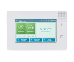
GC3 Control Panel - Front View
Features
The system includes:
»
Touchscreen Display:
A large, full-color, 7-in (17.8 cm) diagonal touchscreen with
an intuitive, gesture-based user
interface.
»
Piezo Sounder and Internal Speaker:
An 85 dB Piezo Sounder sounds external alarms. An internal spe
aker to
delivers voice annunciations, chimes, other system notifi cation
s.
CAUTION!
Long or repeated exposure to sounds at or above 85 dB can lead
to Noise-Induced Hearing Loss (NIHL).
»
Alarm Button/LED Indicator:
Tap this button to show Panic, Fire, and Emergency buttons. For
more information,
see the GC3 Security & Automation System Fingertip Guide.
»
Home Button/LED Indicator:
A button to wake the touchscreen and give users the ability to
return to the
touchscreen’s Home screen. For more information, see the GC3 Se
curity & Automation System Fingertip Guide.
»
Removable Faceplate:
A removable faceplate concealing a door lock for the Cellular
Radio Module bay.
»
Microphone and Speaker:
A built-in microphone and speaker provide clear 2-Way Voice co
mmunication during
alarm events between users at the GC3 Panel and operators at th
e Central Station.
»
Cellular Radio Module with Internal Antenna:
A snap-in Cellular Radio Module with an internal antenna that fi
ts
neatly in the side panel.
»
24-Hour Backup Battery:
A 24-hour backup battery to support the GC3 Panel during tempor
ary AC power failures
and outages.
»
USB Port:
A convenient USB port at the top of the GC3 Panel that can be
used with a USB thumb drive (not
supplied) to update the system’s fi rmware. See “Update the GC3
Panel Firmware.”
»
WiFi:
The built-in WiFi module allows the system to be connected to a
WiFi network for dual path communication,
OTA updates, and connection with secondary keypads.
»
Ethernet:
(optional) An Ethernet module can be added to the system to all
ow for a hardwired connection to a local
network for dual path communication, OTA updates, and connectio
n with secondary keypads.
»
Access Point:
The built-in Access Point allows for a direct connection with s
econdary keypads via WiFi without
the need to connect to a local network. Copyright © 2019 Nortek Security & Control LLC
8
Capabilities
The system includes these capabilities:
»
Smart Areas:
Smart Areas allows for partitioning the system. Partitioning i
s the process of dividing security
sections of a home or building into smaller areas so that users
can arm some sections of the house while leaving
other areas disarmed. This provides home and building owners bo
th security and convenience, as it allows them to
walk through their structure without concern of tripping alarms
for areas they’d like to keep secure and armed.
»
Security Codes:
The system supports a maximum of 100 unique, programmable, secu
rity codes for accessing
system functions. You are provided with one (1) Master User Cod
e, one (1) Duress Code, and one (1) Installer
Code (reserved for use by 2GIG alarm dealers and installers), a
nd the ability to create 98 additional user codes for
accessing the system.
»
Z-Wave
® and
Z-Wave Plus
™
Compatibility:
Installers (and end users, if confi gured on the system) can ad
d up
to 232 smart home devices to communicate with the GC3 Panel usi
ng the Z- Wave and Z-Wave Plus wireless
communication protocol. The GC3 Panel can be included and opera
ted in any Z-Wave network with other Z-Wave
certifi ed devices from other manufacturers and/or other applica
tions. All non-battery operated nodes within the
network will act as repeaters regardless of vendor to increase
reliability of the network. This device is a security
enabled Z-Wave Plus product that is able to use encrypted Z-Wav
e Plus messages to communicate to other
security enabled Z-Wave Plus products.
»
2-Way Voice:
(Optional) Operators at the Central Station can communicate di
rectly with end users through the
GC3 Panel . Operators can also silently listen-in after receivi
ng a user duress report.
»
Date, Time, and Weather Forecasts
1
: Users can view the current date, time, and weather forecast i
n an easy-to-
read format.
»
System Vocabulary/Voice Descriptors:
A list of vocabulary words integrates with the on-screen user i
nterface
and audio announcements. This lets installers customize the sen
sor names that display on the GC3 Panel , as well
as for the audible system announcements. For example, when some
one opens the front door, the system can be
set up to announce “front door.”
1
Date, Time and Weather Forecasts are supported by most Remote
Service Providers in most regions. Consult your provider to det
ermine if this feature is enabled. Copyright © 2019 Nortek Security & Control LLC
9
Internal Components
This illustration details the GC3 Panel’s internal components.
GC3 Panel - Internal Components
Callout
Component
Description
A
Backup Battery
A backup battery used with the GC3 Panel to exte
nd service during a power
outage.
B
Cellular Radio Module An on-board digital communicator transmit
s alarms and trouble alerts to the
Central Station, and also supports 2-Way Voice communication.
C
Terminal Block
Two terminal blocks with screw-terminal position
s for connecting the GC3
Panel to electrical power (PWR+/PWR1), hardwire loops/wired zon
es (ZONE1/
ZONE2), solid state output (BELL+/BELL-), and an open collector
output (OCL1/
OCL2).
NOTE: Terminals are still marked as 2 Wire Smoke but 2 Wire smo
ke is not
supported
D
Third Hand Hanging
Strap
A durable hanging strap provides installers with an extra hand
when installing
and servicing the GC3 Panel.
E
Receiver Board
The main receiver board.
F
Piezo Sounder
An internal 85-dB Piezo Sounder.
G
GC3 Panel Siren/
Speaker
An internal speaker that sounds loud, clear alarms, navigation
tones, alert
tones, and supports 2-Way Voice communication.
H
WLAN Card
A Wireless LAN card to support the GC3 system’s self-
contained Wi-Fi network.
I
USB Port
A built-in USB port for updating the panel’s fi rmware. Copyright © 2019 Nortek Security & Control LLC
10
Additional Accessories
The installer typically sets up the system to communicate with
a variety of wired and/or wireless sensors. Some sensors
are visible on the wall or ceiling. For example, Wireless Smoke
/Heat/Freeze Alarms and Wireless Carbon Monoxide
Detectors. Others may be hidden in door jambs . For example, Re
cessed Door/Window Contacts. Sensors might also be
installed in additional locations. For example, a Glass Break D
etector and a Passive Infrared Motion Detector.
NOTE:
A variety of 2GIG and GoControl branded devices are compatible
with the GC3 Security & Automation
System. Sensors manufactured by other companies may also be com
patible with the system. For information, visit
dealer.2gig.com
IMPORTANT:
This notation is used to indicate a situation which, if not av
oided, could result in property damage,
equipment damage, or data loss.
IMPORTANT:
To ensure that the system’s sensors are operating properly, it
is important for 2GIG alarm dealers
and system owners to ensure sensor batteries and wireless signa
ls are tested at least once a year.
Depending on the specifi c installation, systems may also be ins
talled with one or more of the following 2GIG accessories:
Kits & Keypads
»
2GIG Control Panel Desktop Kit
»
2GIG SP1 Keypad
»
2GIG SP2 Keypad
»
2GIG PAD1
Radios & Antennas
»
2GIG Cellular Radio Module
»
2GIG External Attic Mount Antenna
Sensors & Peripherals (
eSeries sensors are only
compatible with the GC3e panel
)
»
2GIG Thin Door/Window Surface Contact
»
2GIG Recessed Door/Window Contact
»
2GIG Passive Infrared (PIR) Motion Detector
»
2GIG Glass Break Detector
»
2GIG Smoke/Heat/Freeze Alarm
»
2GIG Smoke/Heat Detector
»
2GIG Panic Button Remote
»
2GIG Carbon Monoxide Sensor
»
2GIG Takeover Module
»
2GIG Doorbell
»
Universal Garage Door Receiver
»
2GIG Tilt Sensor
»
2GIG Bypass Sensor
»
2GIG Flood Sensor
»
2GIG Repeater
Z-Wave Smart Home Controls
Consult your 2GIG alarm dealer for information about
installing a wide variety of compatible Z-Wave smart home
controls including:
»
Lights
»
Locks
»
Thermostats
»
Garage Door Controllers Copyright © 2019 Nortek Security & Control LLC
11
Important Information
The GC3 Security & Automation System conforms to the Security I
ndustry Alarm Coalition’s
ANSI/SIA CP-01-2010:
Control Panel Standard - Features for False Alarm Reduction.
The system also meets the residential security system
certifi cation criteria for the ETL Listed Mark.
For Residential Settings
When installing the system in a residential setting, be aware o
f the following:
»
Fire warning systems must be installed in accordance with nati
onal codes:
In the United States, fi re warning
systems must be installed in accordance with
ANSI/NFPA 72: National Fire Alarm and Signaling Code
and
ANSI/
NFPA 70: National Electric Code.
Before installing this system, always ensure that you are in c
ompliance with any
national, regional, and local laws, rules, and/or guidelines.
»
A permit may be required for this alarm system:
Some cities and municipalities may require an alarm system
permit. Before installing this system, always ensure that you a
re in compliance with any national, regional, and
local laws, rules, and/or guidelines.
»
This system is intended for use with approved-model smoke alarm
s only:
For use as a smoke alarm system,
there must be at least one (1) approved 2GIG-branded smoke alar
m programmed into the GC3 Panel. See
dealer.2gig.com.
»
Failure to follow ETL requirements voids this system’s ETL List
ed Mark:
Failure to install the GC3 Panel and
accessories in accordance with the ETL requirements documented
in this manual voids its ETL Listed Mark.
Operating Temperature
The recommended storage temperature for the GC3 Panel is -10°C
to 60°C (14°F to 140°F). For optimal use, operation
temperature is 0°C to 49°C (32°F to 120°F). No altitude range l
imitations have been reported while transporting the GC3
Panel.
Create the Installation Plan
Before installing the system, the fi rst step is to create an
installation plan for the premises. Next, determine the
mounting location for all system components, including the
GC3 Panel and all sensors. If the system includes wired
sensors, you will need to connect the wiring to the GC3
Panel’s terminal block.
Recommended Tools and Equipment
To install the system, these tools and equipment are
recommended:
»
2-Conductor Power Wire (if connecting the GC3
Panel’s power supply to the system’s terminal block)
»
Drywall Saw (or Equivalent)
»
Ladder
»
Magnetic Phillips Head Screwdriver
»
Screwdrivers
»
Staple Gun
»
Wire Stripper
Where to Mount the GC3 Panel
When choosing a location for mounting the GC3 Panel,
work with the end user to determine the best location. See
also “Create the Installation Plan” above. For best results,
keep the following items in mind:
»
Always choose an indoor location that is protected
from temperature extremes.
»
Always choose a location that is above ground and
centrally located.
»
Always choose a location where you can connect
the GC3 Panel to an unswitched outlet. Do NOT
connect the GC3 Panel to a switch-controlled outlet.
»
Always choose a location above ground level. Do
NOT install the GC3 Panel below ground level, as
this can impair wireless range.
»
Avoid choosing a location that can be easily viewed
from doors or windows.
»
Avoid choosing a location that is within reach of
small children.
»
Avoid choosing a location in direct sunlight.
NOTE:
If mounting the GC3 Panel on a wall is not
an option, the 2GIG Desktop Kit can be purchased
for use with the GC3 Security & Automation System.
This is an accessory that lets one mount the GC3
Panel on a stand that can be placed on a fl at
surface, such as desk or counter. Use of this option
may aff
ect compliance with state or regional codes. Copyright © 2019 Nortek Security & Control LLC
12
Where to Place Wireless Sensors
When placing the system’s wireless sensors, it is important to
remember that they communicate with the GC3 Panel
over radio frequency (RF). This subjects the system to radio in
terference, which can be caused by a variety of sources,
such as other RF devices, construction materials, or even when
placing sensors in close proximity to other appliances,
electronic devices, or electrical wiring.
CAUTION!
While the GC3 Panel includes a sensitive receiver that typical
ly allows for placement of wireless
sensors in nearly all locations, it is important to always inst
all sensors in areas that provide the best possible signal
strength.
To ensure the system and sensors are placed appropriately, revi
ew the following illustration.
Control Panel Location Relative to Sensors
CORRECT
Centrally Locate
Control Panel
INCORRECT
Sensors at the other end of the
house might be too far away
Control Panel Location Height
CONTROL
PANEL
Basement
CORRECT
Mount Control Panel as HIGH
above earth level as practical
INCORRECT
Locating Control Panel below
earth level impairs range
Sensor Signal Loss Through Materials
90% - 100%
Of Full Power
65% - 95%
Of Full Power
10% - 70%
Of Full Power
Wallboard and
Wood Studs
Light Concrete
Or Brick
Concrete with Steel
Reinforcement or Metal
Lath and Plaster
Location of Sensors
SENSOR
DOOR
Minimum
3 ft
Concrete
slab
floor
DOOR
Concrete
slab
floor
Less
than
3 ft
above
slab
SENSOR
SENSOR
Wall
CORRECT
CORRECT
INCORRECT
Large
metal
appliance
(refrig.)
CONTROL
PANEL
Basement Copyright © 2019 Nortek Security & Control LLC
13
Where to Place Burglary Protection Sensors
The following diagram shows a typical residential installation
and the various types of wireless sensors and their function.
Burglary Protection Sensors—Residential Installation
CP
ES
DW
PIR
CP - CONTROL PANEL
DW - DOOR/WINDOW SENSOR
PIR - MOTION DETECTOR
GB - GLASS BREAK SENSOR
PAD - WIRELESS KEYPAD
ES - EXTERNAL SIREN
LIVING
DINING
KITCHEN
ENTRY
BATH
DEN
GB
BED
DW
DW
DW
DW
DW
DW
DW
DW
FRONT AND SIDE DOOR SENSORS
(WITH ENTRY/EXIT DELAY)
DW
BED
DW
GARAGE
GB
PAD
PIR
DW
DW
DW
MAIN AND SIDE GARAGE DOOR SENSORS
(WITH ENTRY/EXIT DELAY)
diag-gc3-burglary-floor-plan-en Copyright © 2019 Nortek Security & Control LLC
14
Where to Place Fire Protection Sensors
IN THE UNITED STATES, CANADA, AND OTHER COUNTRIES REQUIRED TO M
EET THIS STANDARD: THIS
EQUIPMENT MUST BE INSTALLED IN ACCORDANCE WITH CHAPTER 2 of ANS
I/NFPA 72: National Fire Alarm and
Signaling Code (National Fire Protection Association, Batteryma
rch Park, Quincy, MA 02269).
Where NOT to Install a Smoke Alarm
»
Do NOT install a smoke alarm in a location where the normal amb
ient temperature is below 40°F (4.4°C) or higher
than 100°F (37.8°C). Do NOT install a smoke alarm directly abov
e a sink, shower, or bathtub.
»
Do NOT mount a smoke alarm next to a door or window aff
ected by drafts. For example, do NOT install near an
extractor fan or air vent. Do NOT mount a smoke alarm outside.
The alarm is designed for indoor use only.
»
Do NOT mount a smoke alarm in or below a cupboard.
»
Do NOT mount a smoke alarm in a location where air fl ow is obst
ructed by curtains, furniture, or other items. Do
NOT mount a smoke alarm where dirt, dust, or grease can collect
and block the sensor.
»
Do NOT mount a smoke alarm where it can be knocked, damaged, or
inadvertently removed.
»
Do NOT place any smoke alarm within 10 ft (3.04 m) of a kitchen
appliance, furnace, water heater, or other source
of combustion to minimize the risks of setting off
a nuisance alarm.
Recommended Smoke Alarm Placement
Early warning fi re detection is best achieved when fi re detecti
on equipment is installed in all rooms and areas of the
premises. Equipment should be installed as follows:
Recommended Smoke Alarm Placement
DINING
KITCHEN
BEDROOM
BEDROOM
BEDROOM
LIVING
ROOM
SMOKE
ALARM
A smoke alarm should be located between the sleeping
area and the rest of the family living unit.
BEDROOM
BEDROOM
BEDROOM
TV
ROOM
DINING
KITCHEN
SMOKE
ALARMS
LIVING
ROOM
In family living units with more than one (1) sleeping
area, a smoke alarm should be provided to protect
each sleeping area.
Indicates a required smoke alarm
Indicates an optional smoke alarm
if door is not provided between
living and recreation rooms
Indicates additional smoke alarms
required for new construction
BED
ROOM
BED
ROOM
LIVING
ROOM
HALL
BASEMENT
DINING
ROOM
A smoke alarm should be
located on each story.
IMPORTANT
: Regulations pertaining to smoke alarm installations vary. For more information, contact your local fire
department or local authority having jurisdiction.
LIVING
ROOM
BASEMENT
BED
ROOM
HALL
BED
ROOM
RECREATION ROOM
A
B
C
D
In split-level configurations, smoke
alarms are optional where a door is
not provided between a living and
recreation room. Copyright © 2019 Nortek Security & Control LLC
15
Installation Steps
When installing the GC3 Security & Automation System, use the s
teps below as a general guideline. Before you begin,
make sure that you have created the Installation Plan. See “Cre
ate the Installation Plan.”
1. Unpack the System:
Unpack the system and ensure you have all of the required tools
and components.
2. Install the Cellular Radio Module:
Ensure the Cellular Radio Module is properly installed. Verify
cell coverage
with the proposed panel location in the home. See “Install the
GC3 Cellular Radio Module.”
3. Mount the GC3 Panel’s Backplate:
If you will be mounting the GC3 Panel on the wall, identify th
e best location
for the GC3 Panel near an unswitched power outlet. Then use the
GC3 Panel’s backplate to mark the wiring cutout
locations and mount the backplate to the wall. See “Mount the G
C3 Panel’s Backplate.”
NOTE:
If mounting the GC3 Panel on a wall is not an option, the 2GIG
Desktop Kit can be purchased for use with
the GC3 Security & Automation System. This is an accessory that
lets one mount the GC3 Panel on a stand that
can be placed on a fl at surface, such as desk or counter. Use o
f this option may aff
ect compliance with state or
regional codes.
4. Connect an External Alarm Sounder:
If the property will be protected by an external alarm sounder,
install the
alarm sounder following the instructions provided with the soun
der. Once installed, route the sounder’s wiring to
the appropriate screw terminals on the GC3 Panel’s terminal blo
ck. See “Connect an External Alarm Sounder.”
5. Connect the Hardwire Loops:
If the property will be protected by any wired sensors, route
the hardwire loop
wiring to the appropriate screw terminals on the GC3 Panel’s te
rminal block. See “Connect the Hardwire Loops.”
6. Connect the Power Wires:
There are two methods of connecting power to the GC3 Panel. Co
nnect the power
cord using the barrel connector or connect a 2-conductor power
wire (not supplied) to the appropriate screw
terminals on the GC3 Panel’s terminal block. See “Connect the P
ower Wires.”
7. Connect the Backup Battery:
Before connecting the GC3 Panel to the AC power source, ensure
the backup
battery is connected. See “Connect the Backup Battery.”
8. Install the Wall Bracket and AC Power Supply:
After mounting the GC3 Panel on the wall, install the wall
bracket and then plug in the AC Power Supply. See “Install the
Retaining Wall Bracket and Connect the AC Power
Supply.”
9. Install the Sensors and Peripheral Devices:
Follow the Installation Instructions included with each sensor
and
peripheral that you plan to install.
10. Program the Sensors & Peripherals:
Program the system’s wireless and wired zones, as well as any
keyfobs or
keypads. See “Programming Sensors & Peripherals.”
11. Complete the Panel Programming Steps
: Program settings for the GC3 Panel and the rest of the system
. See
“Panel Programming.” Copyright © 2019 Nortek Security & Control LLC
16
Installing the System
Install the GC3 Cellular Radio Module
The 2GIG GC3 Cellular Radio Module is a snap-in unit providing
the GC3 Security & Automation System with
communication to the Central Station for alarm signaling and de
livering (Over-the-Air) OTA fi rmware updates to the GC3
Panel. It also provides connectivity to the Remote Service Prov
ider and 2-way voice communication. The module also
includes a built-in antenna to provide a consistently strong co
mmunication signal.
The illustration below shows you the top view and bottom view o
f the GC3 Cellular Radio Module.
GC3 Cellular Radio Module—Top & Bottom View
Install/Replace the Cellular Radio Module
System Completely Powered OFF
To install/replace the Cellular Radio Module into a system that
is completely powered OFF:
1. Remove the hinged door from the GC3 Control Panel.
Cellular Radio Module—Hinged Door
NOTE:
If you are not able to remove the door, remove the door-lock sc
rew for the Cellular Radio Module bay. See
“(Optional) Lock/Unlock the Cellular Radio Module Door.”
2. If you are replacing a module, pull the tab to remove the Ce
llular Radio Module. Otherwise, skip this step and
continue with step 3.
3. Insert the GC3 Cellular Radio Module until it clicks into pl
ace.
4. Replace the hinged door.
5. (Optional) Install the lock on the Cellular Radio Module bay
door. See “(Optional) Lock/Unlock the Cellular Radio
Module Door.”
6. Power up the system and wait for the Control Panel to recogn
ize the Cell Radio Module. (This may take up to 5
minutes to complete.).
7. After installing the Cellular Radio Module, go to the
Installer Toolbox > System Confi
guration > Radio Test
.
Then tap
Start Radio Test
. When the test reads “Success,” tap
Done
. Copyright © 2019 Nortek Security & Control LLC
17
System Powered ON
To replace the Cellular Radio Module into a system that is powe
red ON:
1. From the Home screen, tap
System Settings
.
2. From the System Settings menu, tap
Cell Radio Swap
.
3. Tap Begin.
4. If the Cellular Radio Module bay is locked, remove the facep
late and then move the door-lock screw to the
UNLOCK position. See “(Optional) Lock/Unlock the Cellular Radio
Module Door.”
5. Remove the hinged door from the GC3 Control Panel.
Cellular Radio Module—Hinged Door
6. Pull the tab to remove the Cellular Radio Module.
7. Insert the GC3 Cellular Radio Module until it clicks into pl
ace.
8. (Optional) Install the lock on the Cellular Radio Module bay
door.
9. Replace the hinged door.
10. Tap
Done
. Copyright © 2019 Nortek Security & Control LLC
18
(Optional) Install the External Radio Module Antenna
To install the optional External Radio Module Antenna, follow t
hese steps:
1. Disconnect the AC power supply from the power source.
2. Remove the Control Panel from the backplate and secure the p
anel with the Third Hand Hanging Strap
3. Disconnect the battery from the Control Panel.
4. If the Cellular Radio Module is already installed, remove th
e hinged door from the GC3 Control Panel and pull the
tab to remove the Cellular Radio Module. Otherwise, skip this s
tep and continue with step 5.
5. Remove the three (3) screws that secure the Cellular Radio M
odule cover and remove the cover.
Cellular Radio Module—Remove Cover
6. Disconnect the antenna from the Cell Radio Module PCB and re
move the antenna.
7. Connect the external antenna to the Cell Radio Module PCB.
Cellular Radio Module—Route Antenna Cable
8. Route the external antenna cable out through the slot on the
bottom of the module.
9. Replace the Cellular Radio Module cover and secure with the
three screws.
10. Secure the antenna cable within the channel on the bottom o
f the module.
11. Route the external antenna into the Control Panel and inser
t the Cellular Radio Module into the Control Panel until
it clicks into place.
12. Route the antenna cable through the wiring cutout on the GC
3 Control Panel’s backplate.
13. Connect the battery to the Control Panel.
14. Mount the Control Panel on the backplate.
15. Connect the AC power supply to the power source. Copyright © 2019 Nortek Security & Control LLC
19
(Optional) Install the External Attic Mount Cellular Radio Modu
le Antenna
If you will be installing the optional External Attic Mount Cel
lular Radio Module Antenna, follow these steps:
1. Mount the antenna plate as high as possible on a wall or in
the attic.
2. Drop the antenna’s 10-foot cable down to the GC3 Panel.
External Attic Mount Cellular Radio Module Antenna
3. Route the antenna cable through the wiring cutout on the GC3
Panel’s backplate.
4. Route the antenna cable and attach it to the connector on th
e Cellular Radio Module.
(Optional) Lock/Unlock the Cellular Radio Module Door
The Cellular Radio Module fi ts into the bay on the side of the
GC3 Panel and features a built-in door lock under the
faceplate. The Control Panel ships with the door-lock screw in
the UNLOCK position. To limit the possibility of someone
removing the door, installers have the option of moving the scr
ew to the LOCK position.
GC3 Cellular Radio Module Door Lock Copyright © 2019 Nortek Security & Control LLC
20
To lock and unlock the Cellular Radio Module door:
1. Use your fi ngertips or carefully insert a screwdriver at the
edge of the faceplate. Then gently pry the faceplate from
the chassis.
GC3 Panel—Removeable Faceplate
2. Remove the door-lock screw from the UNLOCK position on the r
ight.
GC3 Panel—UNLOCK position
3. Install the screw into the LOCK position on the left. This l
ocks the hinged door on the GC3 Control Panel.
GC3 Panel—LOCK position
4. Snap the faceplate back on the GC3 Control Panel. Mount the
GC3 Panel’s Backplate Copyright © 2019 Nortek Security & Control LLC
21
Mount the GC3 Panel’s Backplate
Before mounting the GC3 Panel in its permanent location, use th
e guidelines below to choose the placement. Also ensure
you have the recommended tools and equipment. See “Recommended
Tools and Equipment.”
Choose the Wall Location
To choose a wall location for the GC3 Panel, see “Where to Moun
t the GC3 Panel.”
Mount the Backplate to a Wall
To mount the backplate to a wall:
1. Position the GC3 Panel at the desired location on the wall.
2. Insert a pencil into the placement feature on the top of the
panel and make a mark in the reference groove.
3. Loosen the locking screw on the bottom of the GC3 Panel. Thi
s allows the backplate to be removed from the rest
of the chassis.
NOTE:
The locking screw cannot be removed from the panel. Do not use
excessive force to remove the captive
screw from the case.
GC3 Panel Backplate—Nonremovable Locking Screw
4. Separate the backplate from the GC3 Panel. The backplate hin
ge is located on the top of the panel. Remove the
bottom of the backplate fi rst.
5. Press the backplate fl ush against the wall at the mounting l
ocation.
NOTE:
The backplate has a built-in level to ensure the GC3 Panel hang
s straight.
GC3 Panel—Built-in Level
6. Use the backplate as a template to mark the location of the
wiring cutout. Then cut a slot in the dry wall for the AC
power cord and other electrical wiring (if needed).
7. Route the barrel connector for the power supply or 2-conduct
or
wire (if connecting power to the GC3 Panel’s terminal block) th
rough
the wiring cutout.
8. If you are installing any hardwire loops, an external alarm
sounder, an external in-wall antenna, or open collector outputs
that
must be connected to the GC3 Panel’s terminal block, route thos
e
wires through the cutout.
WARNING!!
To avoid serious injury or death while wiring the
terminal block connections, do NOT connect the GC3 Panel’s
power supply to a power source and always ensure that you
disconnect the backup battery before servicing the panel’s
internal components.
9. Attach the backplate to the wall using the four (4) wall anc
hors
and screws (supplied). The center top screw is the wall tamper
and
MUST have an anchor to work. Copyright © 2019 Nortek Security & Control LLC
22
10. Attach the backplate to the wall using the four (4) wall an
chors and screws (supplied). The center top screw is the
wall tamper and MUST have an anchor to work.
GC3 Panel—Backplate Installation
NOTE:
If you are upgrading the control panel from the previous versio
n, you can reuse the two (2) GC2 mounting
screws.
11. Attach the GC3 Panel’s third-hand hanging strap to the hoo
k at the bottom of the backplate. Optional Desktop Kit
Optional Desktop Kit
NOTE:
If mounting the GC3 Panel on a wall is not an option, the 2GIG
Desktop Kit can be purchased for use with
the GC3 Security & Automation System. This is an accessory that
lets one mount the GC3 Panel on a stand that
can be placed on a fl at surface, such as desk or counter. Use o
f this option may aff
ect compliance with state or
regional codes.
Optional 2GIG Desktop Kit—Rear View Copyright © 2019 Nortek Security & Control LLC
23
Connect an External Alarm Sounder
The terminal block inside the GC3 Panel includes two (2) solid-
state bell terminals (BELL+/BELL-) for an external alarm
sounder. An external alarm sounder is typically housed outside
of a property, in a location that will attract the most
attention, in order to scare unwanted intruders away with an au
dible alarm (and sometimes also a strobe light). When
choosing a location for the sounder, ensure it is protected fro
m harsh weather (either housed indoors or in a weatherproof
box). It should also be mounted in a location where the siren c
an be easily heard by occupants.
»
If you are installing a new external sounder:
First, install the external sounder in the desired location. T
hen
route the wiring to the GC3 Panel’s terminal block.
»
If you are replacing an existing external sounder:
First, install the replacement sounder in the desired location
.
Then route the wiring to the GC3 Panel’s terminal block.
»
If an external sounder is already installed:
First, disconnect power to the external sounder. Then route the
sounder’s existing wiring to the GC3 Panel’s terminal block.
IMPORTANT:
The GC3 Panel is designed to connect to Solid-State Relay sound
ers only. To avoid damage to
the output, do NOT connect an Electromechanical Relay bell to t
he BELL+ or BELL- position on the GC3 Panel’s
terminal block. In addition, bell output is only provided when
the GC3 Panel’s power supply is connected to an AC
power source.
To connect an external alarm sounder to the GC3 Panel:
1. Install the sounder in a secure, weatherproof location where
it can be easily heard.
2. Disconnect the sounder from its power source.
3. Ensure the GC3 Panel is disconnected from both the AC power
source and the backup battery.
4. Route the wiring from the sounder through the back of the GC
3 Panel’s wiring cutout.
5. Connect the sounder’s wires to the BELL+ and BELL- positions
on the GC3 Panel’s terminal block.
NOTE:
For sounders with low current consumption, low current relays,
or in the event that the Piezo Sounder
produces a humming sound or noise, install an 820Ω resistor in
parallel with the sounder.
Wiring Diagram—Bell Output
TIP:
After the installation is complete, navigate to
the
Panel Programming
menu to confi gure siren
supervision. This lets the system notify both the user
and the Central Station if the wire between the external
alarm sounder and GC3 Panel is cut. By default, this
setting is turned OFF. See “Q28: Siren supervision time.” Copyright © 2019 Nortek Security & Control LLC
24
Connect the Hardwire Loops
The GC3 Panel supports up to two (2) wired zones. Typically, th
ese zones are used for hardwired Door/Window contact
sensors. You fi rst install the contact sensors and then route t
he loop wiring to the GC3 Panel. This type of connection is
commonly referred to as hardwire loops.
IMPORTANT:
The GC3 Panel’s hardwire loops are designed to support contact
sensors such as magnetic reed
switches or pressure pads. They are not designed for hardwire s
moke detectors, carbon monoxide detectors,
motion detectors, or glass break detectors.
TIP:
If you are planning to upgrade the existing wired security syst
em at the home or business to a wireless system
or if you have a need to retrofi t any pre-wired sensors in newe
r construction for wireless, you can purchase the
2GIG Hardwire Conversion Kit ( 2GIG-TAKE-KIT1) .
To install the hardwire loop wiring for the contact sensors:
1. Install the wired contact sensors.
2. Route the contact sensor’s loop wire(s) through the back of
the GC3 Panel’s wiring cutout.
3. Use the diagram below as a guide for connecting the sensor’s
loop wires to the GC3 Panel terminal block.
»
Normally Closed (N/C):
Used for Normally Closed (N/C) circuits. This means the circui
t on the contact switch is
closed when the magnets are aligned on the door/window contact.
When armed, the GC3 Panel activates an alarm
signal it detects that the door or window is no longer in the n
ormally closed state.
»
Normally Open (N/O):
Used for Normally Open (N/O) circuits. This means the circuit o
n the contact switch is open
when the magnets are aligned on the door/window contact. When a
rmed, the GC3 Panel activates an alarm signal
when it detects that the door or window is no longer in the nor
mally open state.
»
End-of-Line Resistor (EOLR):
Used to supervise the sensor for open or short circuit conditio
ns with an End- of-
Line Resistor (EOLR). If EOLR supervision is required, you must
install a 2.2 kΩ resistor (not supplied). End of
Line Resistors must be installed at the location in the loop fa
rthest away from the panel. This feature allow for the
use of an EOL resistor for existing zones.
NOTE:
For compliance with UL 38: Manual Signaling Boxes for Fire Alar
m Systems, stranded conductors
clamped under wire binding screws or similar parts shall have t
he individual strands soldered together or shall be
equivalently arranged.
Wiring Diagram—Hardwire Loops
TIP:
After the installation is complete, you must program the wired
zone into the GC3 Panel. During programming,
you must defi ne the normal state of the circuit for each wired
zone. See “Program a Wired Zone.” Copyright © 2019 Nortek Security & Control LLC
25
Connect the Power Wires
There are two ways to connect the wires for the power supply to
the GC3 Panel:
1. Terminal Block:
Securely fasten a 2-conductor power wire (not supplied) to the
appropriate PWR+/PWR- screw
positions on the GC3 Panel’s terminal block.
2. Barrel Connector:
A plug-in power supply with a barrel connector can be plugged i
nto the DC power adapter’s
barrel jack on the GC3 Panel.
IMPORTANT: When selecting a wall outlet, never connect the plug
-in power supply to a switch-controlled outlet.
Maximum Wire Gauge and Length
American Wire Gauge
(AWG)
Maximum Length
(feet)
Maximum Length
(meters)
22 AWG
50
16.8
20 AWG
80
25.9
22 AWG 2-pairs
(19 AWG equivalent)
110
33.5
18 AWG
125
41.1
Terminal Block
The most common way to connect the AC power supply for the GC3
Panel is to use the system’s terminal block. This
requires you securely fasten 2- conductor power wire (not suppl
ied) to the appropriate PWR+/PWR- screw terminals.
GC3 Panel—Terminal Block
To connect the power supply to the GC3 Panel:
1. Locate an unswitched wall outlet for the plug-in power suppl
y. Do NOT
connect the power supply to the outlet at this time.
2. Route 2-conductor power wire from the plug-in power supply t
hrough
the wiring cutout on the GC3 Panel’s backplate. See “Connect th
e Power
Wires” above.
WARNING!!
The proper wiring sequence for the DC power supply
terminal block is always ground to ground, positive to positive
, and
negative to negative. However, grounding the GC3 Panel is NOT
required for proper operations.
3. Insert the positive wire into the PWR+ terminal position. Th
en tighten
the terminal block’s contact screw.
IMPORTANT:
Do not over-tighten the terminal block’s contact screws.
NOTE:
Terminal 1 only provides power for the GC3 Panel when its powe
r
supply is connected to an AC power source. Copyright © 2019 Nortek Security & Control LLC
26
5. Insert the negative wire into the PWR- terminal position. Th
en tighten the terminal block’s contact screw.
GC3 Panel—Terminal Block Power
WARNING!!
Do NOT plug the power supply into the outlet at this time. Alwa
ys complete all system wiring and then
secure the backplate to the GC3 Panel before connecting its pow
er supply to the outlet.
Barrel Connector
An alternate method for connecting the AC power supply for the
GC3 Panel is to use the optional barrel connector.
To connect the power supply’s barrel connector to the GC3 Panel
:
1. Locate an unswitched wall outlet for the plug-in power suppl
y. Do NOT connect the power supply to the outlet at
this time.
2. Route the power wire from the plug-in power supply through t
he wiring cutout on the GC3 Panel’s backplate.
3. Plug the barrel connector into the DC power adapter barrel j
ack on the back of the GC3 Panel.
GC3 Panel—Barrel Connector to DC Power Jack
WARNING!!
Do NOT plug the power supply into the
outlet at this time. Always complete all system wiring
and then secure the backplate to the GC3 Panel
before connecting its power supply to the outlet. Copyright © 2019 Nortek Security & Control LLC
27
Control Panel Wiring Diagram
The following diagram shows the Control Panel wiring.
Control Panel Wiring Diagram
ALL output
voltages are
Class 2
Terminal 1 only
provides power when
the Control Panel’s
power supply is
connected to an
AC power source
CONTROL
PANEL
1 – 14VDC Power Input (+)
2 – 14VDC Power Input (–)
3 – COM
4 – Bell (+)
5 – Bell (–)
6 – ZONE 1
7 – ZONE 2
OBSERVE POLARITY
when connecting the
Power Supply
Plug-in 14 VDC
1.7 AMP
Switching
Power Supply
Piezo
Siren
Supervised
Bell Output
14 VDC
@ 500 mA
Maximum
2.2 K
Normally
Closed
Contact
2.2 K
Normally Closed
Contact
UL NOTE: Wiring for
all wired sensors
and annunciators
must use UL Listed
low voltage Class 2
or better grade wire.
Sensor and display
voltages must comply
with Class 2 low
voltage requirements
End-of-Line
Resistors
are
optional
on
hardwire
loops
Open
Collector
Output
250 mA
@ 16 VDC
Maximum
Example
hookup
showing
an armed
LED. The
Open Collector
output can be
programmed
to activate
during various
conditions.
1 K
LED
1234
5
678 Copyright © 2019 Nortek Security & Control LLC
28
Terminal Blocks Wiring Diagram
The GC3 Panel includes an 8-position terminal block and a 6-pos
ition terminal block. The table below describes each
position on the terminal blocks.
Terminal Block Positions*
Terminal Block Positions
Position Label
Output
Voltage
Maximum Length
(meters)
1
CLASS 2
14 VDC Power Input (+). Only provides
power when the GC3Panel’s power supply is
connected to an AC power source.
2
CLASS 2
14 VDC Power Input (-)
3
CLASS 2
Ground (Low Side Hardwire Zone)
4
CLASS 2
Bell +
5
CLASS 2
Bell -
6
CLASS 2
Hardwire Loop Zone 1
7
CLASS 2
Hardwire Loop Zone 2
8
CLASS 2
Ground (Lowside Hardwire Zone)
9*
CLASS 2
Transmit (RS232 TX) (Image Sensor)
10*
CLASS 2
Receive (RS232 RX) (Image Sensor)
11
CLASS 2
Open Collector Output 1
12
CLASS 2
Open Collector Output 2
13
CLASS 2
(+) Image Sensor
14
CLASS 2
Not supported Copyright © 2019 Nortek Security & Control LLC
29
Connect the Backup Battery
After connecting or wiring the DC power supply on the panel, us
e these steps to connect the backup battery.
To connect the backup battery:
1. Ensure the backup battery is properly seated in the GC3 chas
sis. The battery’s label should be facing up and
the battery’s connector wire should be on the left with the wir
e running in the empty space between the battery
compartment and Cellular Radio Module’s compartment
2. Insert the wired battery pin into the PCB battery connector.
The connector is located directly behind the DC power
adapter barrel jack.
GC3 Panel—Backup Battery Connector
Important:
The GC3 Panel will not recognize the
backup battery connection until you plug the AC power
supply into the wall outlet.
Warning!!:
Do NOT plug the power supply into the
outlet at this time. Always complete all system wiring
and then secure the backplate to the GC3 Panel before
connecting its power supply to the outlet.
Hang the GC3 Panel
To hang the GC3 Panel on the mounting plate:
1. Ensure all installed wiring is securely fastened.
2. Ensure the connector to the Piezo Sounder is secure.
GC3 Panel—Interal Siren/Speaker Connector
3. Ensure the connector to the internal siren/speaker is
secure.
4. Place the backplate over the lower lip on the back of
the chassis and fl
ip the GC3 Panel upwards.
5. Push the GC3 Panel over the mounting bracket until it
clicks into place.
Note:
Continue with the next step in the section
that follows titled, “Install the Retaining Wall Bracket
and Connect the AC Power Supply.”
Ethernet Module Installation (Optional)
An Ethernet module can be added to the GC3 Panel to
allow a hardware network connection to the system.
Note:
Only a single broadband is available on the
GC3 panel at any time. If a hardwired connection
is active on the GC3 the WiFi connection will be
disabled. Copyright © 2019 Nortek Security & Control LLC
30
Install the Retaining Wall Bracket and Connect the AC Power Sup
ply
After you have completed all of the required system wiring and
connected the battery backup, install the wall bracket and
connect the AC power supply to the wall receptacle.
Note:
When power is initially applied to the panel it should not be
face down. In addition, do not touch the panel
buttons until after the panel is powered up.
Note:
For compliance with ANSI/NFPA 70: National Electric Code in the
United States, you must install the power
supply retaining bracket. Use of the power supply retaining bra
cket is not required in Canada.
To install the wall bracket and connect the AC power supply:
1. Locate an unswitched wall outlet for the plug-in power suppl
y. Do NOT connect the power supply to the receptacle.
2. Peel the adhesive backing off
the power supply’s retaining wall bracket and attach it to th
e receptacle.
3. Secure the bracket to the wall using the fastening screw.
4. Spread the ears of the retaining bracket apart. Then plug th
e power supply into the outlet.
Retaining Wall Bracket—Standard-Style Duplex Receptacle
Retaining Wall Brackect—Decora-Style Duplex Receptacle
5. Thread zip ties through the slots on the power supply and fa
sten them securely.
Wall Bracket Zip Tie—Standard-Style Duplex Receptacle
Wall Bracket Zip Tie—Decora-Style Duplex Receptacle
With the installation complete, you can begin programming senso
rs and peripherals for use with the GC3 Panel. See
“Programming Sensors & Peripherals.” Copyright © 2019 Nortek Security & Control LLC
31
Update the GC3 Panel Firmware
As 2GIG releases fi rmware updates for the GC3 Panel,
download the update to a USB thumb drive and then
connect it to the USB port on the GC3 Panel.
To update the fi rmware:
1. Download the latest fi rmware update from
dealer.2gig.com.
2. Copy the fi rmware update to a USB thumb drive (not
supplied).
Note:
The USB thumb drive must be FAT/FAT
32 formatted. The system will not read an NTFS
formatted thumb drive.
3. Remove the USB protector from the USB port on
the top of the GC3 Panel.
GC3 Panel-—USB Protector
4. Insert a thumb drive storing the desired fi rmware
version into the USB port at the top of the GC3
Panel.
GC3 Panel—USB Port
The
Firmware Update
icon appears in the
Status Icons
area and the
Firmware Update Available
from
USB
Device
message appears.
5. Tap Update.
Firmware Update Available from USB Device
Note:
Firmware Update Available from USB Device
message appears for approximately 10 seconds.
If you are not able to tap the
Update
button in the
message in that time, you can alternately tap the
System Settings
button or the
Firmware Update
button in the system icons area. Then enter the
Master User Code, and then tap
Firmware Update
to start the update process.
The GC3 Panel turns BLACK
and in a few moments,
the
Updating Firmware
message appears.
Important:
During the update process, do NOT
disconnect the GC3 Panel from its power source
and do NOT remove the USB thumb drive until the
update is complete.
When complete, the system restarts automatically and a
new message appears in the system’s Inbox to notify users
that the fi rmware update was successful.
6. On the Home screen, tap the Inbox system icon.
Then tap
Messages
.
Inbox Messages - Update with Areas on Control Panel Illustration
On the
Messages
screen, tap the
GoControl Firmware
Update
message.
7. On the
Messages
screen, tap the
GoControl
Firmware Update
message. Copyright © 2019 Nortek Security & Control LLC
32
Messages
8. Review the message as needed. Then tap
Delete,
Mark as Read
, or
Mark as Unread
as desired.
New Message
Navigate to the Installer Toolbox
When installing sensors and peripherals for use with
system, refer to the
Installation Instructions
included with
each product. Once you know where you will install the
sensors, you can program them for use with the GC3
Panel. To do this, use the
Installer Toolbox
menu.
The
Installer Toolbox
is the primary menu used by 2GIG
alarm dealers and professional installers. It provides these
users with access to system and peripheral programming
functions for the GC3 Security & Automation System. There
are two (2) ways to navigate to the
Installer Toolbox
menu. Use the system logo in the top-right corner of the
Home screen (or a menu) or access it from the
System
Settings
menu.
Note:
To use this feature, you must enter the
Installer Code. The factory default setting is 1561.
To navigate to the Installer Toolbox:
»
At the Home screen or one of the menus, tap the
logo in the top- right corner. Then enter your code to
access the Installer Toolbox.
OR
»
At the Home screen, tap System Settings. Then,
enter your code and tap Installer Toolbox.
Navigate to the Installer Toolbox Menu
The
Installer Toolbox
menu is shown below.
Installer Toolbox Window
Broadband
The built-in WiFi module and optional Ethernet
module allow for broadband connection for dual-path
communication, OTA updates, and connection with
secondary keypads.
Dual Path
Dual path communication is enabled by the backend
provider if available and allows for 2-way communications
between the panel and backend over broadband (WiFi
or Ethernet) with the cell radio as a second path of
communication.
Note:
2-way voice communication is available by
cell radio only.
OTA
“Over the Air” updates by broadband are supported for
fi rmware v.3.1.0+, and High-Speed OTA is supported for
fi rmware v.3.1.3+. Check with your backend provider about
discounted pricing for OTA over broadband.
Secondary Keypads
Broadband is also used for connection of secondary
keypads (SP1 and SP2). Keypads can be connected to
the same client WiFi as the main panel or to the systems
internal Access Point. See the section “Access Point.” Copyright © 2019 Nortek Security & Control LLC
33
Attaching to a Wireless Network
Attach to a Wireless Network
1. Navigate to Installer Toolbox menu and tap
Network
Settings
.
Installer Toolbox
2. Tap
Wireless
.
Wireless Selection
A list of available networks will be displayed.
3. Tap
Network
to connect to.
Select Wireless Network
4. Enter network password and tap
Next
.
Keyboard Entry Screen
You will see the IP Address and other network information.
Wireless Network Setup
Note:
This WiFi connection only connects the panel to
the local network. WiFi is required for connecting wireless
touchscreens to the GC3 Panel.
Selection Buttons
Refresh
Network Options
Tapping
Refresh
will refresh the list of available networks. Copyright © 2019 Nortek Security & Control LLC
34
WPS
Tapping
WPS
allows you to connect securely to routers that
support WPS.
1. Tap
WPS
on GC3 Panel.
WPS Button
2. Tap
Connect
.
Connect Button
3. Locate and press
WPS
on router.
GC3 Panel will securely connect with the router.
Join Other Network
Tapping
Join Other Network
allows you to join a network
not shown in the list.
1. Tap
Join Other Network
.
Join Other Network
2. Enter network SSID.
3. Select authentication type used by the network.
4. Enter password.
Forget Network
Forget Network
Tapping
Forget Network
disconnects the GC3 Panel from
the wireless network and erases the password so that it will
not automatically reconnect to the network.
Wired (Ethernet)
Attaching to a Wired Network (Ethernet Network)
Attach to a Wired Network.
1. Navigate to
Installer Toolbox
menu and tap
Network Settings
.
2. Tap
Wired
.
If the DHCP server is available on the network, the GC3
panel will automatically receive an IP address. Copyright © 2019 Nortek Security & Control LLC
35
See the section “Setting up a Static IP address” to manually
confi gure a static connection to the network.
3. Tap ▼.
NOTE:
Hardwired connection must be active for
the Wired tile to be available. Once a hardwired
connection is active the Wireless (WiFi) tile will be
greyed out.
Access Point
Setup the GC3 Panel Access Point
1. Navigate to the
Installer Toolbox
menu and tap
Network Settings
.
2. Tap
Access Point
3. Enable Access Point
»
Optional:
Press
Edit
icon next to default SSID,
enter new SSID name
»
Optional:
Press
Edit
icon next to
Password
, enter
new password
»
Optional:
Press
Edit
icon next to
IP address,
the
last two octets of the Access Point can be changed
to customize setup.
4. After any edits have been made, press
Save
Access Point Settings
to save any confi guration
settings.
Note:
Make a note of SSID and Password for use in
WiFi setup of SP1 and SP2 keypads.
5. Tap ▼.
Setting Up a Static IP Address
By default the the GC3 Panel will connect using DHCP to
get the IP Address assignment. If you want to set a Static
IP Address, follow these steps.
1. Tap
Manual
and select the
Edit
icon for
IP Address
.
Auto/Manual
2. Enter the desired IP Address.
IP Address
3. Select the edit icon for
SubNet Mask
and enter the
desired
SubNet Mask Address
.
Subnet Mask Copyright © 2019 Nortek Security & Control LLC
36
4. Select the
Edit
icon for
Gateway
and enter the
desired
Gateway Address
.
Gateway Address
5. Select the
Edit
icon for
DNS Server
and enter the
desired
DNS Server Address
.
6. Tap
Confi
gure Network Settings.
Confi gure Network Settings
Network Test
Testing the Broadband network connection
1. Navigate to the
Installer Toolbox
menu and tap
Network Test
.
2. Tap
Start
.
3. The Network test will run:
»
If successful green dots will appear under each test:
LAN, Internet, and Backend.
»
If a failure is detected a red dot will appear under
the test.
»
LAN
– Connection to Local Network
»
Internet
– Connection to Internet
»
Backend
– Connection to Alarm.com
NOTE:
Correct any network issues to resolve
broadband connectivity
4. Tap
to return to Installer Toolbox Copyright © 2019 Nortek Security & Control LLC
37
2. At the
Installer Toolbox
menu, tap
System
Confi
guration
.
Navigate to the System Confi guration Menu
Program a Wireless Zone
The GC3 Panel lets you program a maximum of 100
wireless zones. To begin zone programming, navigate
to the
Installer Toolbox
. See “Navigate to the Installer
Toolbox” above. Then, tap
System Confi
guration
>
Wireless Zones
.
NOTES:
When programming eSensors (Wireless & Keyfobs)
the equipment code must match the sensor being
installed. See page 68 for eSensor Equipment
Codes.
eSeries sensors are only compatible with the GC3e
panel.
Wireless Zones Menu
This reveals the
Wireless Zones
screen shown below.
Step 1: Select a Wireless Zone
First, select the wireless zone to edit.
1. On the left side of the
Wireless Zones
screen,
swipe up or down to move through the list of zones.
2. Tap one of the available zones to highlight it.
Pairing with a System
This feature allows the panel to pair with approved third-
party systems.
1. Navigate to the
Installer Toolbox
and tap
System
Pairing
.
Tap System - Pairing Mode
2. Press the
+
button to start the pairing process.
System Pairing - Enter Key
The system will listen for the pairing request from the third
party system.
Programming Sensors and Peripherals
Navigate to the System Confi
guration Menu
The System Confi guration menu provides installers with
access to programming features for wireless zones, wired
zones, keyfobs, and keypads. It also provides installers
with access to panel programming options.
To navigate to the
System Confi
guration
menu:
1. Navigate to the
Installer Toolbox
. See “Navigate to
the Installer Toolbox.” Copyright © 2019 Nortek Security & Control LLC
38
Note:
A zone is available for programming when it
appears in gray text. A zone that has already been
programmed appears in black text.
3. Tap
Edit Zone
.
Wireless Zones Screen
This reveals the
Wireless Zones <###>
screen.
NOTE:
S1 is the pirmary Smart Area (partition) and
default.
Step 2: Select a Sensor Type
Next, select the appropriate sensor type for the sensor or
peripheral being programmed.
1. At the
Wireless Zone <###>
screen, highlight
Sensor Type
.
2. Tap
to expand the list.
3. Tap to select the appropriate sensor type from the
list.
For example, if you are programming a
Thin Door/Window
Contact for a Front Door
, you might select
01-Exit/Entry
as
the sensor type.
Wireless Zone <###> Screen—Sensor Type
Tip:
You can alternatively use the touchscreen
keypad to enter the two-digit code to select the
Sensor Type
.
4. Tap ▼.
Step 3: Select the Sensor Equipment Type
Note:
If you selected
04-Interior Follower, 06-24-
Hour Silent Alarm, 07- 24-Hour Audible Alarm, 08-
24-Hour Auxiliary Alarm, 10-Interior with Delay
, or
23-No Response Type
in “Step 2: Select a Sensor
Type” above, you must also select the
Sensor
Equipment Type
. If you selected a diff
erent
Sensor
Type
, skip this step and continue with “Step 4:
Select the Equipment Code” below.
1. At the Wireless Zone <###> screen, highlight
Sensor Equipment Type.
2. Under Sensor Equipment Type, choose Contact
or Emergency or Motion. Available options vary
depending on the selected Sensor Type.
3. Tap ▼.
Step 4: Select the Equipment Code
Next, select the four-digit equipment code. For a list of
codes, see “Equipment Code.”
1. At the
Wireless Zone <###>
screen, highlight
Equipment Code
.
2. Tap
to expand the list.
3. Tap to select the desired equipment code from list.
Wireless Zone Screen—Equipment Code
Tip:
You can alternatively use the touchscreen
keypad to enter the four-digit
Equipment Code
.
See “Equipment Code.”
4. Tap ▼.
Step 5: Enter the Serial Number (TX ID)
Next, enter the 7-digit TX ID (this is product’s serial
number) for the sensor or peripheral. This is typically
affi
xed to the product and/or its packaging. To enter the
number, choose one of these options:
»
Touchscreen Keypad Entry:
Use the touchscreen
keypad to type the TX ID into the system.
OR
»
Learning Mode Entry:
Place the GC3 Panel into
Learning Mode and then trigger the sensor twice
to transmit the TX ID from the sensor to the GC3
Panel. Copyright © 2019 Nortek Security & Control LLC
39
1. At the
Wireless Zone <###>
screen, highlight
Serial Number
.
2. Place the GC3 Panel into Learning Mode by tapping
Learn
.
Wireless Zone Screen—Serial Number Keypad
The panel listens for the 7-digit TX ID transmission from the
sensor or peripheral.
Wireless Zone Screen—Learning Serial Number
Tip:
Instead of placing the GC3 Panel into Learning
Mode, you can alternatively use the touchscreen’s
keypad to manually enter the 7-digit TX ID. Or, if you
have previously programmed the wireless zone, you
can tap the
button to the right of the entry display
fi eld to automatically paste the last entered serial
number (TX ID).
3. Trigger the sensor or peripheral. To learn how,
see the
Installation Instructions
that came with the
product. When the panel receives the sensor’s
7-digit TX ID, the
Sensor Received
message
appears.
4. Verify that the serial number on the touchscreen
matches the 7-digit TX ID on the sensor or
peripheral. Then tap
Accept
.
5. Tap ▼.
Step 6: Smart Areas Assignment
Select a Smart Area Assignment.
1. At the
Wireless Zone<###>
screen, highlight
Smart
Areas Assignment
.
2. Under
Smart Areas Assignement
, choose a Smart
Area (Partition) for the zone.
3. Tap ▼.
Step 7: Choose the Equipment Age
Next, choose the equipment age.
1. At the
Wireless Zone <###>
screen, highlight
Equipment Age
.
2. Under
Equipment Age
, choose
New
or
Existing
.
3. Tap ▼.
Wireless Zone Screen—Equipment Age
Step 8: Choose the Sensor Loop
A sensor loop is a communication channel that informs
the system how to respond when events are triggered.
Most 2GIG sensors and peripherals are designed to use
Loop 1
as the default setting. However, some sensors
and peripherals have additional features and programming
options that require a sensor loop. For example, when
programming the Wireless Smoke/Heat/Freeze Alarm,
you can program it for smoke detection using
Loop 1
, for
heat detection using
Loop 2
, and/or for freeze detection
using
Loop 3
. Always check the Installation Instructions
that came with the sensor or peripheral or consult with your
dealer. Copyright © 2019 Nortek Security & Control LLC
40
Note:
When programming wireless sensors and
peripherals, each loop programmed for a wireless
sensor is treated as its own zone by the GC3 Panel.
Note:
If the serial number (TX ID) for the sensor
was added using Learning Mode, the sensor loop
will typically be automatically selected for you.
However, you must verify that the loop number is
correct.
Next, choose the sensor loop:
1. At the
Wireless Zone <###>
screen, highlight
Sensor Loop
.
2. Choose
Loop 1
,
Loop 2
, or
Loop 3
.
Note:
To determine the appropriate loop number,
see the
Installation Instructions
included with the
sensor or peripheral. If the serial number was
entered using the Learning Mode in Step 5, the loop
will automatically be added.
3. Tap ▼.
Wireless Zone Screen—Sensor Loop
Step 9: Enable or Disable the Transmission Delay
Next, turn the Transmission Delay ON or OFF. When
enabled, the feature is ON and the system uses the dialer
delay. The transmission delay specifi es the amount of time
the system waits for it to initiate the digital transmission
when an alarm condition is triggered (see “Q39: Alarm
abort window transmission delay.” When set to OFF, the
dialer delay is not used.
Note:
This setting does not apply to CO or smoke
alarms.
1. At the
Wireless Zone <###>
screen, highlight
Dialer Delay
.
2. Under
Dialer Delay
, choose
Enabled
or
Disabled
.
3. Tap ▼.
Wireless Zone Screen—Transmission Delay
Step 10: Select a Voice Descriptor
Next, create a voice descriptor for the sensor or peripheral
using the words in the system’s vocabulary. See “Voice
Descriptor.”
1. At the
Wireless Zone <###>
screen, highlight
Voice
Descriptor
.
2. Tap
Edit Voice Descriptor
to reveal the
touchscreen keypad.
Wireless Zone Screen—New Voice Descriptor
Step 11: Enable or Disable Sensor Reports
Next, turn the sensor reports feature ON or OFF. When
enabled, the feature is ON and the system sends a report
to the Central Station when the sensor or peripheral
triggers an alarm. When disabled, the feature is OFF and
reports are not sent to the Central Station.
Note:
If this report feature is turned OFF< the
sensor can still be used to trigger an alarm.
1. At the
Wireless Zone <###>
screen, highlight
Sensor Reports
. Copyright © 2019 Nortek Security & Control LLC
41
2. Under
Sensor Reports
, choose
Enabled
or
Disabled
.
Wireless Zone <###>—Sensor Reports
3. Tap ▼.
Step 12: Enable or Disable Sensor Supervision
Next, turn the
Sensor Supervised
option ON or OFF.
When enabled, the feature is ON and the GC3 Panel
checks for regular, wireless transmissions from the
sensor or peripheral. If the GC3 Panel doesn’t receive a
transmission from the sensor after a set amount of time, the
system issues a loss of supervision trouble report. When
disabled, the feature is OFF.
Note:
Because portable sensors (for example, the Panic
Button Remote) are frequently moved out of the system’s
range when users leave the premises, always disable the
Sensor Supervised
for panic buttons. A sensor will still
report to the Central Station with supervision disabled.
1. At the
Wireless Zone <###>
screen, highlight
Sensor Supervised.
2. Under
Sensor Supervised
, choose
Enabled
or
Disabled
.
3. Tap ▼.
Wireless Zone <###>—Sensor Supervised
Step 13: Choose a Chime
Next, select the desired chime for the sensor or peripheral.
1. At the
Wireless Zone <###>
screen, highlight
Sensor Chime
.
2. Choose the desired chime from the
Sensor Chime
list. The default setting is
Disabled
.
Wireless Zone <###>—Sensor Chime
Next Steps
You have fi nished programming a wireless zone. You can
now choose one of these options:
»
To program the next wireless zone, tap
Next
Zone
and repeat the programming steps for
another sensor. The system keeps track of all
your programming changes and prompts you to
permanently save all your changes as a group when
you exit the
System Confi
guration
menu.
»
To program the next wireless zone, tap uu|. This
button becomes visible and available only when
programming the last setting for a zone.
»
To erase all of the settings you just programmed for
the zone, tap
Reset Zone
.
»
To permanently save the settings you just
programmed, tap
Return to System Confi
guration
.
Then tap
. At the
Confi
rm Changes
screen, tap
Save
. Copyright © 2019 Nortek Security & Control LLC
42
Program a Wired Zone
The GC3 Panel lets you program a maximum of two (2)
wired zones. To begin zone programming, navigate to the
Installer Toolbox
. See “Navigate to the Installer Toolbox.”
Then, tap
System Confi
guration
>
Wired Zones
.
System Confi guration > Wired Zones
This reveals the
Wired Zones
screen shown in step that
follows.
Step 1: Select a Wired Zone
First, select the wired zone to edit:
1. On the left side of the
Wired Zones
screen, review
the list of zones.
2. Tap one of the available zones to highlight it.
Note:
A zone is available for programming when it
appears in gray text. A zone that has already been
programmed appears in black text.
3. Tap Edit Zone.
Wired Zones—Edit Zone Button
Step 2: Select a Sensor Type
Next, select the appropriate sensor type for the sensor or
peripheral being programmed.
1. At the
Wired Zone <###>
screen, highlight
Sensor
Type
.
2. Tap
to expand the list.
3. Tap to select the appropriate sensor type from the
list.
Wired Zone <###>—Sensor Type
If you selected
04-Interior Follower, 06-24-Hour Silent
Alarm, 07- 24-Hour Audible Alarm, 08-24-Hour Auxiliary
Alarm, 10-Interior with Delay, or 23-No Response Type
in
“Step 1: Select a Wired Zone” above, you must also select
the
Sensor Equipment Type
. If you selected a diff
erent
Sensor Type, skip this step and continue with “Step 3:
Choose the Equipment Age” below.
Tip:
You can alternatively use the touchscreen
keypad to enter the two-digit code to select the
Sensor Type
.
4. Tap ▼.
Step 3: Select a Smart Area Assignment
Select the Smart Area Assignment.
1. At the
Wired Zone<###>
screen, highlight
Smart
Areas Assignment
.
2. Under
Smart Areas Assignment
, choose the Smart
Area (Partition) for the zone.
3. Tap▼.
Wired Zone <###>—Choose Smart Area Copyright © 2019 Nortek Security & Control LLC
43
Step 4: Choose the Equipment Age
Next, choose the equipment age:
1. At the
Wired Zone <###>
screen, highlight
Equipment Age
.
2. Under
Equipment Age
, choose
New
or
Existing
.
Figure 23 Wired Zone <###>—Equipment Age
3. Tap ▼.
Step 5: Choose the Normal State
Next, choose the normal state of the circuit for the
switching component for the wired sensor or peripheral.
1. At the
Wired Zone <###>
screen, highlight
Normal
State
.
2. Under
Normal State
, choose one of these options:
»
Not Used:
Turns the switching component OFF and
disables the use of the sensor or peripheral for the
zone. This is the default setting.
»
Normally Closed (NC):
Sends an alert signal to
the security system when the sensor’s circuit is no
longer in the NC state. For example, if the security
system was armed and a wired door/window contact
programmed as NC goes into the NO state, the
change from NC to NO would trigger an alarm.
»
Normally Open (NO):
Sends an alert signal to
the security system when the sensor’s circuit is no
longer in the NO state. For example, if the security
system was armed and a wired door/window contact
programmed as NO goes into the NC state, the
change from NO to NC would trigger an alarm.
»
End-of-Line Resistor (EOL):
Choose this option
when an end-of-line (EOL) resistor is present.
Note:
An EOL resistor must be installed at the
sensor, not at the panel.
Wired Zone <###>—Normal State
Step 6: Enable or Disable the Transmission Delay
Next, turn the Transmission Delay ON or OFF.
1. At the
Wired Zone <###>
screen, highlight
Transmission Delay
.
2. Under
Transmission Delay
, choose
Enabled
or
Disabled
.
Wired Zone <###>—Transmission Delay
3. Then tap ▼.
Step 7: Select a Voice Descriptor
Next, create a voice descriptor for the sensor or peripheral
using the words in the system’s vocabulary. See “Voice
Descriptor.”
1. At the
Wired Zone <###>
screen, highlight
Voice
Descriptor
. Copyright © 2019 Nortek Security & Control LLC
44
2. Tap
Edit Voice Descriptor
to reveal the
touchscreen keypad.
Wired Zone <###>—Edit Voice Descriptor
3. At the touchscreen keypad, enter the fi rst few letters
of the desired vocabulary word.
4. Tap the matching vocabulary word above the
touchscreen keypad to select it.
Voice Descriptor—Touchscreen Keypad Entry
Note:
You can scroll through the list of vocabulary words by
swiping to the right or the left.
5. Repeat the steps above to enter the desired phrase.
Enter up to six words to create a voice descriptor.
6. Tap
Done
.
Voice Descriptor—Touchscreen Keypad Entry
7. Review the voice descriptor.
Review Voice Descriptor
8. Tap ▼.
Step 8: Enable or Disable Sensor Reports
Next, turn the sensor reports feature ON or OFF. When
enabled, the feature is ON and the system sends a report
to the Central Station when the sensor or peripheral is
triggered. When disabled, the feature is OFF and reports
are not sent to the Central Station.
1. At the
Wired Zone <###>
screen, highlight
Sensor
Reports
.
2. Under
Sensor Reports
, choose
Enabled
or
Disabled
.
3. Tap ▼.
Step 9: Choose a Chime
Next, select the desired chime for the sensor or peripheral.
1. At the
Wired Zone <##>
screen, highlight
Sensor
Chime
. Copyright © 2019 Nortek Security & Control LLC
45
2. Choose the desired chime from the
Sensor Chime
list. The default setting is
Disabled
.
Wired Zone <###>—Sensor Chime
Next Steps
You have fi nished programming a wired zone. You can now
choose one of these options:
»
To program the next wired zone, tap
Next Zone
and
repeat the programming steps for another sensor.
The system keeps track of all your programming
changes and prompts you to permanently save all
your changes as a group when you exit the
System
Confi
guration
menu.
»
To program the next wired zone, tap uu|. This
button becomes visible and available only when
programming the last setting for a zone.
»
To erase all of the settings you just programmed for
the zone, tap
Reset Zone
.
»
To permanently save the settings you just
programmed, tap
Return to System Confi
guration
.
Then tap
. At the
Confi
rm Changes
screen, tap
Save
.
Program a Keyfob
The GC3 Panel lets installers program up to 32 portable
keyfobs per system. To begin zone programming, navigate
to the
Installer Toolbox
. See “Navigate to the Installer
Toolbox.” Then tap
System Confi
guration
>
Keyfobs
.
NOTES:
When programming eSensors (Wireless & Keyfobs)
the equipment code must match the sensor being
installed. See page 68 for eSensor Equipment
Codes.
eSeries sensors are only compatible with the GC3e
panel.
System Confi guration Menu
This reveals the
Keyfobs
screen shown in the next step.
Step 1: Select a Keyfob
First, select the keyfob to edit.
1. At the Keyfobs screen, swipe up and down to move
through the list of keyfobs.
2. Tap to select one of the available keyfobs.
Note:
A keyfob is available for programming when it
appears in gray text. A keyfob that has already been
programmed appears in black text.
3. Tap
Edit Keyfob
.
Keyfobs Screen—Edit Keyfob
This reveals the Keyfobs screen shown in the next step.
Step 2: Enable or Disable the Fob Used
Next, enable or disable the Fob Used option. When
enabled, the keyfob is ON and can be used with the
system. When disabled, the keyfob is OFF and cannot be
used with the system (this is the default setting).
1. At the
Keyfob <###>
screen, highlight
Fob Used
. Copyright © 2019 Nortek Security & Control LLC
46
2. Under
Fob Used
, choose
Enabled
or
Disabled
.
Keyfobs <###> Screen—Fob Used
3. Tap ▼.
Step 3: Select Equipment Code
Next, select the equipment code for the keyfob.
1. At the Keyfob <###> screen, highlight Equipment
Code.
2. Tap
to expand the list.
3. Tap to select the desired equipment code from the
list.
Keyfob <###> Screen—Equipment Code
Tip:
You can alternatively use the touchscreen
keypad to enter the four-digit Equipment Code. See
“Equipment Code.”
4. Tap ▼.
Step 4: Enter Serial Number
Next, enter the 7-digit TX ID (this is product’s serial
number) for the keyfob. This is typically affi
xed to the
product and/or its packaging. To enter the number, choose
one of these options:
»
Touchscreen Keypad Entry:
Use the touchscreen
keypad to type the TX ID into the system.
OR
»
Learning Mode Entry:
Place the GC3 Panel
into Learning Mode and then trigger the keyfob
to transmit the TX ID from the keyfob to the GC3
Panel.
1. At the
Keyfob <###>
screen, highlight
Serial
Number
.
2. Place the panel into Learning Mode by tapping
Learn
.
Keyfob <###> Screen—Serial Number
The panel listens for the 7-digit TX-ID transmission from the
sensor or peripheral.
Keyfob <###> Screen—Listening for TX ID
3. Press any button on the keyfob for three (3) to
fi ve (5) seconds. When the TX ID is received, the
Sensor Received
message appears.
4. Verify the serial number on the touchscreen
matches the keyfob’s 7-digit TX ID. Then tap
Accept
. Copyright © 2019 Nortek Security & Control LLC
47
Keyfob <###> Screen—Accept Serial Number
Tip:
Instead of placing the GC3 Panel into Learning
Mode, you can manually enter the 7-digit TX ID on
the keyfob.
5. Tap ▼.
Step 5: Selecting the Smart Area Assignment
Select a Smart Area Assignment.
1. At the
Wireless Zone<###>
screen, highlight
Smart
Areas Assignment
.
2. Under
Smart Areas Assignment
, choose a Smart
Area (Partition) for the zone.
3. Tap ▼.
Keyfob <###> Screen—Choose Smart Area
NOTE:
If Smart Areas option is enabled (Q69),
keyfob can be assigned to a single Smart Area and
will arm/disarm and initiate alarms (if programmed)
on the assigned Smart Area only.
Step 6: Choose the Equipment Age
Next, choose the equipment age.
1. At the
Keyfob <###>
screen, highlight
Equipment
Age
.
2. Under
Equipment Age
, choose
New
or
Existing
.
Keyfob <###> Screen—Equipment Age
3. Tap ▼.
Step 7: Enable the Emergency Key
Next, choose whether simultaneously pressing the
Arm
Away
and
Disarm
buttons on the keyfob triggers an
emergency alarm.
1. At the Keyfob <###> screen, highlight Emergency
Key.
2. Under Emergency Key, choose one of these
options:
»
Disabled:
This turns the emergency key function
OFF on the keyfob.
»
Auxiliary:
This setting triggers a 24-hour auxiliary
alarm on the system.
»
Audible:
This setting triggers a 24-hour audible
alarm on the system.
»
Silent Panic:
This setting triggers a 24-hour silent
alarm on the system.
Keyfob <###> Screen—Emergency Key
3. Tap ▼.
Step 8: Enable or Disable Fob Can Disarm
Next, choose whether the keyfob can be used to disarm the
system. When enabled, the keyfob has the ability to disarm
the system. When disabled, the keyfob does not have the
ability to disarm the system. Copyright © 2019 Nortek Security & Control LLC
48
1. At the
Keyfob <###>
screen, highlight
Fob Can
Disarm
.
2. Under
Fob Can Disarm
, choose
Enabled
or
Disabled
.
Keyfob <###> Screen—Fob Can Disarm
3. Tap ▼.
Step 9: Edit Voice Descriptor
Next, create a voice descriptor for the keyfob using the
words in the system’s vocabulary. See “Voice Descriptor.”
1. At the
Keyfob <###>
screen, highlight
Voice
Descriptor
.
2. Tap
Edit Voice Descriptor
to reveal the
touchscreen keypad.
Keyfob Programming—Edit Voice Descriptor
3. At the touchscreen keypad, enter the fi rst few letters
of the desired vocabulary word.
4. Tap the matching vocabulary word above the
touchscreen keypad to select it.
Keyfob Programming—Word Entry Touchscreen
5. Repeat the steps above to enter the desired phrase
for the keyfob. Enter up to six words to make a voice
descriptor.
6. Tap
Done
.
7. Review the voice descriptor.
Keyfob Programming—New Voice Descriptor
8. Tap ▼.
Step 10: Enable or Disable Arm with No Entry
Delay
Next, enable or disable the
Fob Arm with No Delay
option.
When enabled, the option is turned ON, the system ignores
all Entry Delay timers (see “Q5: Entry delay 1, in seconds
(30-240)” and “Q6: Entry delay 2, in seconds (30-240)” )
when a keyfob is used to arm the system. When disabled,
the option is turned OFF and the system uses the Entry
Delay timers when a keyfob is used to arm the system.
1. At the
Keyfob <###>
screen, highlight
Arm with No
Entry Delay
. Copyright © 2019 Nortek Security & Control LLC
49
2. Under
Arm with No Entry Delay
, choose
Enabled
or
Disabled
.
Keyfob Programming—Arm with No Entry Delay
3. Tap ▼.
Step 11: Enable or Disable Fob Output
Finally, select whether the auxiliary (*) button on the keyfob
can be used to trigger the GC3 Panel’s Open Collector #1
output.
1. At the
Keyfob <###>
screen, highlight
Fob
Output
.
2. Under
Fob Output
, choose one of these options:
»
Disabled
: This deactivates the option.
»
Toggle Output
: Choose this option for toggle
output. This lets users press the Auxiliary (*) button
on the fob to control the device that is connected
to the system’s Open Collector Output #1. For
example, to use the keyfob to open and close a
garage door, you would typically choose Toggle
Output.
»
Momentary Output: Choose this option for
momentary output. This lets users press the
Auxiliary (*) button on the fob to control the device
that is connected to the system’s Open Collector
Output #1. For example, to use the keyfob to turn
system-controlled lights ON or OFF, you would
typically choose Momentary Output.
Keyfob <###> Screen—Fob Output
Next Steps
You have fi nished programming a keyfob. You can now
choose one of these options:
»
To program another keyfob, tap
Next Keyfob
and
repeat the programming steps for another keyfob.
The system keeps track of all your programming
changes and prompts you to permanently save all
your changes as a group when you exit the
System
Confi
guration
menu.
»
To program the next keyfob, tap uu|. This
button becomes visible and available only when
programming the last setting for a keyfob.
»
To erase all of the settings you just programmed for
the keyfob, tap
Reset Keyfob
.
»
To permanently save the settings you just
programmed, tap
Return to System Confi
guration
.
Then tap
. At the
Confi
rm Changes
screen, tap
Save
.
Program a Keypad
The GC3 Panel lets you program a maximum of eight (8)
keypads. To begin keypad programming, navigate to the
Installer Toolbox
. See “Navigate to the Installer Toolbox.”
Then tap
System Confi
guration
>
Keypads
.
System Confi guration Menu
This reveals the
Keypads
screen shown in the step that
follows.
Step 1: Select a Keypad
First, select the keypad to edit:
1. On the left side of the Keypads screen, swipe up to
move through the list of keypads.
2. Tap one of the available keypads to select it.
Note:
A keypad is available for programming when
it appears in gray text. A keypad that has already
been programmed appears in black text. Copyright © 2019 Nortek Security & Control LLC
50
3. Tap
Edit Keypad
.
For example, tap
Keypad 1
to select it.
Keypads Screen—Edit Keypad
Step 2: Enable or Disable Keypad Used
Next, enable or disable the keypad. When enabled, the
keypad can be used with the system. When disabled, the
keypad cannot be used with the system.
1. At the
Keypad <###>
screen, highlight
Keypad
Used
.
2. Under
Keypad Used
, choose
Enabled
or
Disabled
.
Keypad <###> Screen—Keypad Used
3. Tap ▼.
Step 3: Select Equipment Code
For a complete list of the system’s four-digit equipment
codes, see “Equipment Code.”
1. At the
Keypad <###>
screen, highlight
Equipment
Code
.
2. Tap
to expand the list.
3. Tap to select the desired equipment code from the
list.
Keypad <###> Screen—Equipment Code
Tip:
You can alternatively use the touchscreen
keypad to enter the four-digit
Equipment Code
.
See “Equipment Codes.”
4. Tap ▼.
Step 4A: Pair SP1 or SP2
Pair the SP1 or SP2 keypad to the system. If
SP1
or
SP2
was selected in
Equipment Code,
this option will show as
Device ID.
NOTE:
If programming a PAD1, the option will show
as Serial Number, follow Step 4B.
»
Before Pairing SP1 or SP2 the system and the
keypad must both be connected to the same
broadband network or keypad must be connect to
the systems internal Access Point via WiFi.
»
Before pairing a SP2, make note of the GC3s
broadband or Access Point IP address before
starting the process.
For more details, see the installation manual of the device.
1. Press
Pair
button.
2. Start pairing process on SP1 or SP2 (See SP1/2
installation manual for details).
3. System will show Device ID when paired.
4. Tap ▼. Copyright © 2019 Nortek Security & Control LLC
51
Step 4B: Enter the PAD1 Serial Number (TX ID)
Next, enter the 7-digit TX ID (this is product’s serial
number) for the keypad. This is typically affi
xed to the
product and/or its packaging. To enter the number, choose
one of these options:
»
Touchscreen Keypad Entry:
Use the touchscreen
keypad to manually enter the TX ID into the system.
OR
»
Learning Mode Entry:
Place the GC3 Panel into
Learning Mode
to automatically enter the TX ID
into the system.
1. At the
Keypad <###>
screen, highlight
Serial
Number
.
2. Place the GC3 Panel into Learning Mode by
tapping
Learn
.
<###> Screen—Serial Number
The panel listens for the 7-digit TX ID transmission from the
keypad.
Keypad <###> Screen—Listening for TX ID
3. Touch and hold any button on the keypad. Consult
the
Installation Instructions
that came with the
product for information on how to trigger it. When
the panel receives the TX ID, the
Sensor Received
message appears.
4. Verify that the TX ID on the touchscreen matches
the one on the product.
5. Tap
Accept
.
Keypad <###> Screen—Accept Serial Number
Tip:
Instead of placing the GC3 Panel into Learning
Mode, you can alternatively use the touchscreen’s
keypad to manually enter the 7-digit TX ID.
6. Tap ▼.
Step 5: Selecting the Smart Area Assignment
Select a Smart Area Assignment.
1. At the
Keypad Zone<###>
screen, highlight
Smart
Areas Assignment
.
2. Under
Smart Areas Assignment
, choose a Smart
Area (Partition) for the zone.
3. Tap ▼.
Keypad <###> Screen—Choose Smart Area
Note:
If Smart Areas option is enabled (Q69),
keypads can be assigned to a single Smart Area.
PAD1 will arm/disarm the assigned Smart Area.
SP2 will arm/disarm the assigned Smart Area and
display Smart Area status. SP1 will arm/disarm the
assigned Smart Area and display that Smart Area
status on the home screen and arming/disarming
and status of all Smart Areas is available from the
Smart Areas
button on the home screen. Copyright © 2019 Nortek Security & Control LLC
52
Step 6: Choose the Equipment Age
Choose the equipment age.
1. At the
Keypad <###>
screen, highlight
Equipment
Age
.
2. Under
Equipment Age
, choose
New
or
Existing
.
Keypad <###> Screen—Equipment Age
3. Tap ▼.
Step 7: Select Emergency Keys
Next, enable or disable the emergency Panic and Fire keys
on the keypad.
1. At the
Keypad <###>
screen, highlight
Emergency
Keys
setting is selected.
2. Under
Emergency Keys
, choose
Enabled
or
Disabled
.
Keypad <###> Screen—Emergency Keys
3. Tap ▼.
Step 8: Select a Voice Descriptor
1. At the
Keypad <###>
screen, highlight
Voice
Descriptor
.
2. On the touchscreen, tap
Edit Voice Descriptor
to
reveal the touchscreen keypad.
Keypad <###> Screen—Edit Voice Descriptor
3. On the touchscreen keypad, enter the fi rst few
letters of the desired vocabulary word.
4. Tap the matching vocabulary word above the
touchscreen keypad to select it.
Touchscreen Keypad—Voice Descriptor Entry
5. Repeat the steps above to enter the desired phrase
for the keypad. Add up to six words to create a voice
descriptor.
6. Tap
Done.
Touchscreen Keypad—Voice Descriptor Entry Done Copyright © 2019 Nortek Security & Control LLC
53
7. Review the voice descriptor.
Keypad <###> Screen—Review Voice Descriptor
Next Steps
You have fi nished programming a keypad. You can now
choose one of these options:
»
To program another keypad, tap
Next Keypad
repeat the programming steps for another keypad.
The system keeps track of all your programming
changes and prompts you to permanently save all
your changes as a group when you exit the
System
Confi
guration
menu.
»
To program the next keypad, tap
. This
button becomes visible and available only when
programming the last setting for a keypad.
»
To erase all of the settings you just programmed for
the keypad, tap
Reset Keypad
.
»
To permanently save the settings you just
programmed, tap
Return to System Confi
guration
.
Then tap
. At the
Confi
rm Changes
screen,
tap
Save
.
The following illustration is an example of the
Wireless
Zones
screen.
Example—Wireless Zones Screen
2. At the
Reset Zone
message, verify that you are
deleting the desired item. Then tap
Reset
.
Reset Zone Message
This restores the factory default settings for the specifi ed
zone, keyfob, or keypad.
Reset a Zone, Keyfob, or Keypad to the Factory
Default Settings
When you reset the GC3 Panel to its factory default
settings, the system erases all of the programmed settings
for any of the zones, keyfobs, or keypads controlled by the
system.
To reset zone, keyfob, or keypad to its factory default
setting:
1. At the
Wireless Zones
,
Wired Zones
,
Keyfobs
, or
Keypads
screen, tap the trash can icon next to the
desired item. Copyright © 2019 Nortek Security & Control LLC
54
two ways to restore the system’s factory default settings:
Hard Reset and Soft Reset.
Choose one of these options:
»
† Allow Reset of All Defaults: Lets installers restore
the factory-default values to the GC3 Panel.
»
Allow Limited Reset of Defaults: Lets installers
restore some of the factory-default values, with the
exception of “Q1: Enter installer code (4 digits)”
above, “Q2: Lock installer programming” above,
“Q3: Lock default programming” above, and “Q7:
Remote services provider.” This setting takes eff
ect
48 hours after the setting is changed, and the
countdown timer starts when you exit the System
Confi guration menu.
»
Do Not Allow Reset of Defaults: Does not let
installers restore the factory default values to the
GC3 Panel. This setting takes when you exit the
System Confi guration menu.
Q4: Exit delay, in seconds (45-120)
Confi gures the number of seconds for the Exit Delay
countdown. Diff
erent times may be programmed for each
Smart Areas. (Smart Areas feature must be enabled
(Q69) for values for S2-S4 to aff
ect the system) This is the
amount of time occupants have to exit the building through
a door after arming the system. The doors programmed as
Exit/Entry 1 and Exit/Entry 2 use this timer. When the user
arms the system, the countdown starts.
The GC3 Panel beeps once every two (2) seconds during
the countdown. For the last 10 seconds, the beeps speed
up to warn occupants that they have less than 10 seconds
to exit the premises.
Choose one of these options:
»
45-120 Seconds: Choose a value between 45 and
120 seconds.
»
† ‡ 60 Seconds: For compliance with ANSI/SIA CP-
01-2010, the default Exit Delay feature is set to 60
seconds.
NOTE:
Arming the system from a remote location
with a web-enabled device, such as a computer
or smart phone, does NOT initiate the Exit Delay
countdown.
Q5: Entry delay 1, in seconds (30-240)
Confi gures the number of seconds for the Entry Delay 1
timer. Diff
erent times may be programmed for each Smart
Areas. (Smart Areas feature must be enabled (Q69) for
values for S2-S4 to aff
ect the system) This specifi es the
amount of time occupants have to disarm the system after
entering the premises through a door. Typically, the primary
entrance programmed as an Exit/Entry 1 door uses this
time. When the user enters the premises, the countdown
timer starts.
The GC3 Panel beeps once every two (2) seconds during
the countdown.
Panel Programming
This section details the Panel Programming questions.
A dagger (†) indicates a factory default setting. A double
dagger (‡) indicates a default setting for compliance with
ANSI/SIA CP-01-2010: Control Panel Standard - Features
for False Alarm Reduction.
Q1: Enter installer code (4 digits)
Defi nes the unique four-digit code for installers to use when
accessing the GC3 Panel’s Installer Toolbox. See “Navigate
to the Installer Toolbox.”
Choose one of these options:
»
† 1561: This is the factory default setting.
»
Enter a unique four-digit code. If you change the
Installer Code, be sure to remember it so you can
access the system later. The Installer Code must
be unique from the Master User Code and all other
user codes.
Important:
To minimize the risk of unwanted
persons circumventing the system, 2GIG alarm
dealers and professional installers are advised to
change the system’s default Installer Code to a
unique one. This helps to prevent unwanted persons
from gaining access to critical programming features
of the GC3 Security & Automation System.
Q2: Lock installer programming
This feature prevents system takeovers by locking the
installer programming features in the System Confi guration
menu after 48 hours. The 48-hour lockout timer starts when
the installer exits System Confi guration mode. To restore
access after the 48-hour period, installers must reset the
lockout timer using the Cellular Radio Module.
When this feature is enabled, the following programming
features are locked out after 48 hours:
“Q1: Enter installer code (4 digits)” above
“Q2: Lock installer programming” above
“Q3: Lock default programming” below,
“Q7: Remote services provider”.
Choose one of these options:
»
† Disabled (Full Access): This turns the feature
OFF. Installer programming remains unlocked after
48-hours.
»
No Access: This turns the feature ON. The
programming features are fully restricted after
48-hours.
»
Limited Access: This turns the feature ON. The
programming features are partially restricted after
48-hours.
Q3: Lock default programming
Prevents system takeovers by limiting the user’s ability to
restore the GC3 Panel’s factory-default settings. There are Copyright © 2019 Nortek Security & Control LLC
55
Choose one of these options:
»
30-240 Seconds: Choose a value between 30 and
240 seconds.
»
† ‡ 30 Seconds: For compliance with ANSI/SIA CP-
01-2010, the default Entry Delay 1 feature is set to
30 seconds.
Q6: Entry delay 2, in seconds (30-240)
Confi gures the number of seconds for the Entry Delay 2
timer. Diff
erent times may be programmed for each Smart
Areas. (Smart Areas feature must be enabled (Q69) for
values for S2-S4 to aff
ect the system) This specifi es the
amount of time occupants have to disarm the system after
entering the premises through a door. Typically, secondary
entrances that require a slightly longer entry time are
programmed as an Exit/Entry 2 door. For example, a
back, side, or garage entry door. When a user enters the
premises while the system is armed, the Entry Delay 2
countdown starts.
The GC3 Panel beeps once every two (2) seconds during
the countdown.
Choose one of these options:
»
30-240 Seconds: Choose a value between 30 and
240 seconds.
»
†‡ 45 Seconds: For compliance with ANSI/SIA CP-
01-2010, the default Entry Delay 2 feature is set to
45 seconds.
Q7: Remote services provider
Confi gures the appropriate Remote Services Provider for
the system. A Remote Services Provider is the third-party
security provider that powers the system’s interactive
services.
Choose one of these options:
»
None: Does not specify the provider.
»
† Alarm.com: Choose this option if the Remote
Services Provider is Alarm.com.
Q8: 2-way voice
Confi gures the system to automatically turn the GC3
Panel’s 2-Way Voice feature ON or OFF after the type of
alarm you specify. This gives the GC3 Panel’s Cellular
Radio Module the ability to automatically dial the
Central Station and connect with an operator after an alarm
sounds. Once connected with the Central Station, people
on the premises can communicate with the operator using
the GC3 Panel’s built-in speaker and microphone.
Choose one of these options:
»
Disabled: Turns the feature OFF.
»
†Stay On Line: Turns the feature ON and
automatically enables the 2-Way Voice feature after
a burglary alarm.
»
Stay On Line, Including Fire & CO Alarms: Turns the
feature ON and automatically enables the 2-Way
Voice feature after a burglary, fi re, and/or carbon
monoxide alarm.
When the Control Panel connects with the operator, it will
beep once every six seconds. The beep alternates between
two tones and indicates the Control Panel is waiting for a
session command. If the operator fails to issue a command
withing three (3) minutes), the call is terminated. Once the
operator presses a command option, the beeps will stop
and a three (3)-minute audio session will start.
When two (2)-way voice communications have been
established, the Central Station operator can use the
following telephone keys to control the communications.
Each time the operator uses a command key, the session
is extended for three (3) additional minutes. During the last
minute of communications, the system beeps two (2) times
every 15 seconds to indicate that time is running out.
»
Tap 1 to enable Talk mode one (1)-way
communication from the Central Station to the
premises and allow the operator to talk.
»
Tap 2 to enable VOX mode two (2)-way
communications from the Central Station to the
premises.
»
Tap 3 to enable Listen mode one (1)-way
communication from the premises to the Central
Station.
»
Tap 7 to extend the session fi ve (5) minutes without
changing the mode of operation.
»
Tap 9 to end the audio session and terminate the
call.
Q9: Disable siren after two-way audio
Confi gures the system to automatically turn the alarm siren
ON or OFF after the end of a 2-Way Voice session. For
this setting to take eff
ect, “Q8: 2-way voice” above must be
enabled.
Choose one of these options:
»
Enabled: Choose this setting if you want the alarm
siren to remain OFF after a 2-Way Voice session
ends.
»
† Disabled: Choose this setting if you want the
alarm siren to resume after a 2-Way Voice session
ends.
NOTE:
When set to disabled, the alarm siren will
only resume after a 2-way voice session when the
corresponding alarm bell cutoff
time has not expired.
See “Q40: Burglary bell cutoff
time” and “Q41: Fire
bell cutoff
time.” Copyright © 2019 Nortek Security & Control LLC
56
Q10: Police emergency key
Confi gures the system to respond in two (2) ways when a
user manually activates a panic alarm on the GC3 Panel.
The system can either be set to emit a loud, patterned
warning siren or to set off
a silent panic alarm with no siren.
You can also disable the Panic button so that it is not visible
on the GC3 Panel.
Choose one of these options:
»
Disabled: Turns the feature OFF and hides the
Panic button from the Alarm screen.
»
† Audible: Turns the feature ON. This makes the
Panic button visible on the Alarm screen. The
system sounds a loud, patterned warning siren after
the user activates a panic alarm.
»
Silent Panic: Turns the feature ON. This makes
the Panic button visible on the Alarm screen. The
system sounds a silent panic alarm with no warning
siren after the user activates a panic alarm.
Q11: Fire emergency key
Confi gures the system to show or hide the Fire button on
the Alarm screen of the GC3 Panel’s touchscreen. When
set to Audible, the button is visible and the system emits
a loud, patterned warning siren when a user manually
activates a fi re emergency alarm on the GC3 Panel.
Choose one of these options:
»
Disabled: Turns the feature OFF and hides the Fire
button from the Alarm screen.
»
† Audible: Turns the feature ON. This makes the
Fire button visible on the Alarm screen. The system
sounds a loud, patterned warning siren after the
user activates a fi re alarm.
Q12: Emergency key
Confi gures the system to show or hide the Emergency
button on the Alarm screen of the GC3 Panel’s
touchscreen. When set to Audible, the button is visible and
the system emits a loud, patterned warning siren when a
user sets off
an emergency alarm on the GC3 Panel.
Choose one of these options:
»
Disabled: Turns the feature OFF and hides the
Emergency button from the Alarm screen.
»
† Audible: Turns the feature ON. This makes the
Emergency button visible on the Alarm screen. The
system sounds a loud, patterned warning siren after
the user activates an emergency alarm.
Q13: Quick arming
Turns the system’s quick arming feature ON and OFF. This
feature can be assiged individually for each Smart Area.
(Smart Areas feature must be enabled (Q69) for settings for
S2-S4 to aff
ect the system) When ON, any occupant can
arm the system. When OFF, only persons who know an
active, four-digit user code can arm the system.
Choose one of these options:
»
† Enabled: Turns the feature ON and does not
require occupants to enter a user code to arm the
system.
»
Disabled: Turns the feature OFF and requires
occupants to enter an active, four-digit user code to
arm the system.
Q14: Auto stay
Turns the system’s Auto Stay feature ON and OFF. This
feature can be assiged individually for each Smart Area.
(Smart Areas feature must be enabled (Q69) for settings
for S2-S4 to aff
ect the system) When ON, the system
monitors the Exit Delay doors after the user arms the
system in Away Mode at the GC3 Panel. If no one exits that
door before the Exit Delay countdown expires, the system
automatically arms itself in Stay Mode. See “Q4: Exit delay,
in seconds (45-120).” This setting does not go into eff
ect
when arming the system in Away Mode with a keyfob.
Choose one of these options:
»
† ‡ Enabled: Turns the feature ON. The system
monitors the Exit Delay door when the system is
armed and if no one exits the door before the Exit
Delay countdown expires, the system automatically
arms the system in Stay Mode. For compliance with
ANSI/SIA CP-01-2010, this feature is enabled by
default.
»
Disabled: Turns the feature OFF. The system arms
itself in Away Mode at the end of the Exit Delay
countdown.
Q15: Exit delay restart
Confi gures the system to restart the Exit Delay countdown
if a user must re-enter the premises through an Exit Delay
door during the initial Exit Delay countdown. This feature
can be assiged individually for each Smart Area. (Smart
Areas feature must be enabled (Q69) for settings for S2-
S4 to aff
ect the system) This is useful when a user arms
the system, exits the premises, and then needs to quickly
enter/exit the premises before the countdown expires. As
long as the user exits the premises during the Exit Delay
Restart countdown, there is no need to disarm and re-arm
the system. When this feature is turned ON, the Exit Delay
timer will restart one (1) time.
Choose one of these options:
»
† ‡ Enabled: Turns the feature ON. If the user exits
and then re-enters the premises before the Exit
Delay countdown expires, the Exit Delay countdown
restarts before the system is armed. For compliance
with ANSI/SIA CP-01-2010, this feature is enabled
by default
»
Disabled: Turns the feature OFF.
NOTE:
When the Exit Delay Restart feature is
enabled on the system and the user arms the Copyright © 2019 Nortek Security & Control LLC
57
system with the Silent Exit feature enabled, the
system will restart the exit countdown using the
Silent Exit timer, instead of the Exit Delay timer.
NOTE:
When the Exit Delay Restart feature is
enabled on the system and the user triggers the
Exit Delay Restart feature, the Quick Exit button is
disabled.
Q16: Allow quick exit
Confi gures the system to allow users to quickly exit the
premises while the system is armed in Stay Mode. When
this feature is turned ON and a user taps Arm Stay, a Quick
Exit button appears on the System Armed screen. When
a user taps Quick Exit , the system starts the Exit Delay
countdown and the user must exit the premises before
the countdown expires. After the countdown expires, the
system automatically re-arms itself in the specifi ed arming
mode.
Choose one of these options:
»
† Enabled: Turns the feature ON. This enables the
Quick Exit button on the System Armed screen.
»
Disabled: Turns the feature OFF.
NOTE:
The Quick Exit button is not available on
the System Armed screen when the user invokes
the Exit Delay Restart feature. See “Q15: Exit delay
restart.”
Q17: Quick bypass
Confi gures the system to allow users to bypass a sensor
without prompting the user to enter a user code. This
feature can be assiged individually for each Smart Area.
(Smart Areas feature must be enabled (Q69) for settings
for S2-S4 to aff
ect the system) Typically, this feature is
disabled, so a user must enter a valid user code before
bypassing a sensor.
Choose one of these options:
»
Enabled: Turns the feature ON.
»
† Disabled: Turns the feature OFF.
Q18: Alert on disarm with keyfob after alarm
Confi gures the system to activate a unique sound when
the system in the alarm state is disarmed by a keyfob.
The unique sound is four (4) beeps from the GC3 Panel’s
speaker and four (4) chirps from an external alarm sounder
(if installed).
Choose one of these options:
»
Enabled: Turns the feature ON. The system emits
the unique sound.
»
† Disabled: Turns the feature OFF.
Q19: Keyfob arm/disarm confi
rmation
Confi gures the system to activate a unique sound when
the system is armed/disarmed with a keyfob. This feature
can be assiged individually for each Smart Area. (Smart
Areas feature must be enabled (Q69) for settings for S2-
S4 to aff
ect the system) When enabled, the GC3 Panel’s
speaker emits one (1) beep when arming and two (2)
beeps when disarming the system with a keyfob. If an
external alarm sounder is installed the system sounds one
(1) chirp when arming and two (2) chirps when disarming
the system.
Choose one of these options:
»
Enabled: Turns the feature ON. The system emits
the unique sound.
»
† Disabled: Turns the feature OFF. The system does
not emit the unique sound.
Q20: Keyfob/remote arming mode on system not
ready
Defi nes how the system behaves when the system is
armed remotely while sensors are open.
Choose one of these options:
»
† Auto-Bypass with Zone Participation on Restore:
Automatically bypasses all open sensors when
the system is remotely armed and, while armed,
automatically removes the bypass if the sensor is
restored to its normal state.
»
Auto-Bypass: Automatically bypasses all open
sensors when the system is remotely armed.
»
Arm Only When System Ready: Does not allow the
system to arm remotely when sensors are open.
Q21: Z-Wave feature
Confi gures the system to show or hide the Smart Home
Controls button on Home screen of the touchscreen. When
this feature is enabled, it provides users with access to the
smart devices on the network, as well as with the ability to
edit scenes and rooms.
Choose one of these options:
»
Disabled and Hidden: Hides the Smart Home
Controls button on the Home screen.
»
Disabled but Visible: Shows the Smart Home
Controls button on the Home screen. When a user
taps the button, the This feature is not currently
activated message displays.
»
Enabled with Local Scenes Hidden: Shows the
Smart Home Controls button, feature is enabled,
and Tile for Scenes is hidden.
»
† Enabled: Shows the Smart Home Controls button
on the Home screen. Users can operate smart
devices from the touchscreen or remotely.
Q22: Smart Home Controls require master code
Confi gures the system to prompt the user for an active,
four-digit user code when attempting to access the Smart
Home Controls menu (if enabled). See “Q21: Z-Wave
feature “ above. Copyright © 2019 Nortek Security & Control LLC
58
Choose one of these options:
»
Enabled: When a user taps the Smart Home
Controls button, the Enter Your Code to Access
Smart Home
»
Controls screen appears.
»
†Enabled: Opens the Smart Home Controls menu,
without prompting the user for a code.
Q23: Master user can access Z-Wave setup
Confi gures the system to allow persons who know the
system’s Master User Code to gain access to the System
Settings > Smart Home Settings menu.
Choose one of these options:
»
Enabled: This makes the Smart Home Settings
button available in the System Settings menu after
entering the Master User Code.
»
† Disabled: This grays out the Smart Home Settings
button and makes it unavailable in the System
Settings menu.
Q24: Temperature display units
Specifi es the temperature scale used by the system to
display weather forecasts on the touchscreen.
NOTE:
Weather forecasts are only available on the
GC3 Panel when enabled by the service provider.
Choose one of these options:
† Fahrenheit: Displays information using the Fahrenheit
temperature scale.
Celsius: Displays information using the Celsius temperature
scale.
Q25: Swinger shutdown count (1-6)
Specifi es the swinger shutdown count for burglary
protection zones. This defi nes the maximum number of
times a zone’s sensor can activate (i.e., “trip”) an alarm
during a single arming session. For example, if the count
is set to two (2) trips, a window contact sensor would be
permitted to trip the alarm a maximum of two (2) times
during a single arming session.
Choose one of these options:
»
1-6 Trips: Use the touchscreen’s numeric keypad to
specify a value between one (1) and six (6) trips.
»
† ‡ 2 Trips: For compliance with ANSI/SIA CP-01-
2010, this is the default setting.
Q26: Cross sensor zones 99-100
Defi nes the alarm verifi cation requirement for a cross
sensor zone. A cross sensor zone is comprised of two
wireless sensors and both sensors must be violated before
the system activates the alarm. This means that before a
cross sensor zone can activate an alarm, the sensors for
both Wireless Zone 99 and Wireless Zone 100 must be
violated.
If only one of the two sensors in the cross sensor zone is
violated, the system automatically transmits a trouble report
about the violated sensor to the Central Station. If both
sensors in the cross zones are violated within the amount
of time specifi ed in “Q27: Cross sensor timeout, in seconds
(10-120),” the system activates an alarm and also transmits
an alarm report to the Central Station.
NOTE:
Carbon Monoxide Detectors and Smoke/
Heat Alarms cannot be used in cross sensor zones.
Choose one of these options:
»
Enabled: Turns the feature ON. The system
transmits a trouble report to the Central Station
when one sensor in a cross sensor zone is violated
and sets off
an alarm when both sensors are
violated.
»
† Disabled: Turns the feature OFF.
Q27: Cross sensor timeout, in seconds (10- 120)
Defi nes the maximum number of seconds it takes the
system to activate an alarm when both sensors in a
cross sensor zone are violated. The value you defi ne
here specifi es the maximum amount of time that can
pass between the violation of sensors programmed for
Wireless Zone 99 and Wireless Zone 100. If both sensors
are violated within the amount of time specifi ed here, the
system activates an alarm. If only one of the sensors is
violated during the timeout interval, the system transmits a
trouble report to the Central Station and does not activate
an alarm.
NOTE:
For the timeout to aff
ect the system, the
Cross Sensor Zones feature must also be enabled
on the system. See “Q26: Cross sensor zones 99-
100.”
You have these options:
»
† 10 Seconds: Defi nes the cross sensor time
interval as 10 seconds.
»
1- 120 Seconds: To extend the timeout interval,
the installer programs a value between 1 to 120
seconds.
Q28: Siren supervision time
Confi gures the system to supervise the wire between an
external alarm sounder (if installed) and the GC3 Panel. In
the event that the supervised wire is cut, the system waits
the number of seconds specifi ed here and then displays
a trouble alert on the GC3 Panel’s touchscreen. It also
transmits a trouble report to the Central Station. “Connect
an External Alarm Sounder.”
Choose one of these options:
»
† Disabled: Turns the feature OFF.
»
15 Seconds: Turns the feature ON. 15 seconds
after a wire cut is detected, the system displays a
trouble alert on the touchscreen and also transmits
a trouble report to the Central Station. Copyright © 2019 Nortek Security & Control LLC
59
»
30 Seconds: Turns the feature ON. 30 seconds
after a wire cut is detected, the system displays a
trouble alert on the touchscreen and also transmits
a trouble report to the Central Station.
»
45 Seconds: Turns the feature ON. 45 seconds
after a wire cut is detected, the system displays a
trouble alert on the touchscreen and also transmits
a trouble report to the Central Station.
Q29: CS lack of usage notifi
cation time, in days
(0-255)
Confi gures the system to monitor itself for lack of usage. If
the system is not armed for the number of days you specify
here, an inactivity report is sent to the Central Station.
Choose one of these options:
»
0 Days: Turns this feature OFF.
»
1-255 Days: Turns this feature ON and transmits
an inactivity report to the Central Station after the
specifi ed number of days.
»
† 7 Days: Turns this feature ON and transmits an
inactivity report to the Central Station after seven (7)
days of inactivity.
Q30: Radio modem network failure time, in min-
utes (0-255)
Confi gures the system to display a trouble alert on the
touchscreen when the system loses its cellular radio
network connection. The number of minutes you specify
here defi nes the amount of down time that must pass
before the system issues a trouble alert report. Once
network service is restored for fi ve (5) minutes, the trouble
alert condition automatically clears itself.
Choose one of these options:
»
0 Minutes: Turns the feature OFF. The system does
not issue a trouble alert
»
1-255 Minutes: Turns the feature ON. Use the
touchscreen’s numeric keypad to enter the number
of minutes between 1 and 255.
»
† 30 Minutes: Turns the feature ON and issues a
trouble alert on the GC3 Panel after 30 minutes of
down time.
Q31: Radio network failure causes trouble
Confi gures the system to display a trouble alert on the
touchscreen when it logs a trouble alert condition with the
cellular network connection. The GC3 Panel will display
an alert message on the touchscreen after the number of
minutes specifi ed in “Q30: Radio modem network failure
time, in minutes (0-255)” above expires.
Choose one of these options:
»
† Enabled: Turns the feature ON. The GC3 Panel
display a visual trouble indicator after a cellular radio
network failure.
»
Disabled: Turns the feature OFF. The GC3 Panel
will not display a visual indicator after a cellular radio
network failure.
NOTE:
Regardless of the setting selected here, a
radio network failure will always be logged in the
System History.
Once the network connection is restored, the system
automatically clears the visual indicator. A record of the
trouble alert condition is stored in the
System History
.
Q32: Radio network failure reports
Confi gures the system to transmit a trouble report to the
Central Station when the system detects a cellular radio
network failure.
Choose one of these options:
»
† Enabled: Turns the reporting feature ON. The GC3
Panel will transmit a trouble report to the Central
Station after a cellular radio network failure.
»
Disabled: Turns the reporting feature OFF. The GC3
Panel will not transmit a trouble report to the Central
Station after a cellular radio network failure.
Q33: Broadband network failure time in minutes
Confi gures the system to display a trouble alert on the
touchscreen when the system loses its broadband network
connection(WiFi or Ethernet). The number of minutes you
specify here defi nes the amount of down time that must
pass before the system issues a trouble alert report. Once
the broadband connection is restored for fi ve (5) minutes,
the trouble condition automatically clears itself.
Choose one of these options:
»
0 minutes: Turns the feature OFF. The system does
not issue a trouble alert
»
1-255 minutes: Turns the feature ON. Use the
touchscreen’s numeric keypad to enter the number
of minutes between 1 and 255
»
† 30 Minutes: Turns the feature ON and issues a
trouble alert on the GC3 Panel after 30 minutes of
down time.
Q34: Broadband network failure causes trouble
Confi gures the system to display a trouble alert on the
touchscreen when it logs a trouble alert condition with the
broadband network connection(WiFi or Ethernet). The GC3
Panel will display an alert message on the touchscreen
after the number of minutes specifed in “Q33: Broadband
network failure time, in minutes (0-255)” above expires.
Choose one of these options:
»
† Enabled: Turns the featur ON. The GC3
Panel displays a visual trouble indicator after the
broadband network failure.
»
Disabled: Turns the feature OFF. The GC3 Panel
will not display a visual indicator after a broadband
network failure. Once the network connection is
restored, the system automatically clears the visual
indicator. A record of the trouble alert condition is
stored in the System History. Copyright © 2019 Nortek Security & Control LLC
60
Q35: Broadband network failure reports
Confi gures the system to tranmit a trouble report to the
Central Station when the system detects a broadband
network connection(WiFi or Ethernet).
Choose one of these options:
»
† Enabled: Turns the reporting feature ON. The
GC3 Panel will transmit a trouble report to the
Central Station after a broadband network failure.
»
Disabled: Turns the reporting feature OFF. The
GC3 Panel will not transmit a trouble report to the
Central Station after a broadband network failure.
Q36: Periodic test, in days (0-255)
Confi gures the system to automatically transmit periodic
test reports about the GC3 Panel’s connections to the
Central Station at the recurring interval you specify here.
Choose one of these options:
»
0 Days: Turns the feature OFF. The system does not
transmit periodic test reports to the Central Station.
»
1-255 Days: Turns the feature ON. The system
transmits periodic test reports to the Central Station
at recurring intervals using the number of days
specifi ed here.
»
† 30 Days: Turns the feature ON. The system
transmits periodic test reports to the Central Station
once every 30 days.
Q37: Alarm cancel time, in minutes (5-255)
Confi gures the system to transmit a cancellation report to
the Central Station whenever an alarm is canceled by a
user within the amount of time specifi ed here. To learn how
to change the setting for the alarm information that displays
on the touchscreen, see “Q38: Alarm cancel display” below.
»
† ‡ 5 Minutes: For compliance with ANSI/SIA CP-
01-2010, the minimum required setting is 5 minutes.
This can be extended to a greater number of
minutes without aff
ecting compliance.
»
6-254 Minutes: Enter a value between 6 and 254
minutes.
»
255: To transmit a cancellation report anytime the
system is disarmed after an alarm, enter 255.
Q38: Alarm cancel display
Confi gures the system to display an alert message letting
the user know that an alarm cancellation report was sent to
the Central Station. The message is displayed if the alarm
is canceled within the number of minutes specifi ed in “Q37:
Alarm cancel time, in minutes (5-255).”
Choose one of these options:
»
† ‡ Enabled: Turns the feature ON. This displays
an alert message notifying the user that an alarm
cancellation report was sent to the Central Station.
For compliance with ANSI/SIA CP- 01-2010, the
default setting for this feature is enabled.
»
Disabled: Turns the feature OFF. The system will not
display an alert message when a cancellation report
is sent to the Central Station.
Q39: Alarm abort window transmission delay
Confi gures the amount of time the system will wait to
initiate the digital transmission when an alarm condition is
triggered. This setting specifi es the number of seconds the
user has to manually abort the alarm, in the event of a false
alarm.
NOTE:
The transmission delay can be increased
to 45 seconds without aff
ecting ANSI/SIA CP-01
compliance only if the combination of Q39 and “Q5:
Entry delay 1, in seconds (30-240)” in “Q6: Entry
delay 2, in seconds (30- 240)” does not exceed one
(1) minute.
Choose one of these options:
»
15 seconds: The system waits 15 seconds to initiate
the dialer.
»
† ‡ 30 seconds: For compliance with ANSI/SIA CP-
01-2010, the default minimum setting is 30 seconds.
This setting can be increased to 45 seconds without
aff
ecting compliance only if the combination of this
setting.
»
45 seconds: The system waits 45 seconds to initiate
the dialer.
Q40: Burglary bell cutoff
time
Defi nes the amount of time the system sounds the burglary
alarm after the alarm is activated. After the time set here
expires, the alarm siren shuts OFF.
NOTE:
This setting only aff
ects the GC3 Panel
alarm. It does not aff
ect any auxiliary alarms that
may be installed. Typically, auxiliary alarms are set
to sound for an unlimited amount of time.
Choose one of these options:
»
† 4 Minutes: The alarm siren shuts OFF after 4
minutes.
»
8 Minutes: The alarm siren shuts OFF after 8
minutes.
»
12 Minutes: The alarm siren shuts OFF after 12
minutes.
»
16 Minutes: The alarm siren shuts OFF after 16
minutes.
»
Unlimited Time: The alarm siren must be shut OFF
manually.
Q41: Fire bell cutoff
time
Specifi es the amount of time a Carbon Monoxide Detector
or Smoke/Heat/Freeze Alarm should sound after the alarm
is activated. After the time set here expires, the alarm siren
shuts OFF.
NOTE:
This setting only aff
ects the GC3 Panel
alarm. It does not aff
ect any auxiliary alarms that Copyright © 2019 Nortek Security & Control LLC
61
may be installed. Typically, auxiliary alarms are set
to sound for an unlimited amount of time.
Choose one of these options:
»
† 4 Minutes: The alarm siren shuts OFF after 4
minutes.
»
8 Minutes: The alarm siren shuts OFF after 8
minutes.
»
12 Minutes: The alarm siren shuts OFF after 12
minutes.
»
16 Minutes: The alarm siren shuts OFF after 16
minutes.
»
Unlimited Time: The alarm siren must be shut OFF
manually.
Q42: Trouble doesn’t sound at night
Prevents audible trouble alerts from waking users during
nighttime hours. When this feature is turned ON, audible
trouble alerts are suppressed between the preconfi gured
hours of 10:00 PM - 9:00 AM. This setting does not
suppress any other trouble alert features. The system
will continue to display trouble alert messages on the
touchscreen. It will also continue to transmit trouble reports
to the Central Station, as well as to log trouble alerts in the
system’s Alarm History.
If the reported trouble condition clears on its own or a
user acknowledges the condition(s) on the Control Panel
before 9:00 AM, no trouble tones will sound after 9:00 AM.
However, the trouble condition is recorded in the system’s
Alarm History.
Choose one of these options:
»
† Enabled: Turns the feature ON.
»
‡ Disabled: Turns the feature OFF. For compliance
with UL 985: Household Fire Warning System Units,
this setting must be disabled.
Q43: Z-Wave siren mode
Confi gures the system to sound any Z-Wave sirens that
have been added to the network.
Choose one of the options:
»
† Sound for Burglary and Fire/CO: Confi gures the
system to sound any connected Z-Wave sirens
during a burglary, fi
re, or CO alarm.
»
Sound for Burglary Only: Confi gures the system to
sound any connected Z-Wave sirens during burglary
alarms only.
Q44: Open collector #1 output
Defi nes output mode for the external device connected to
the OCL1 position of the GC3 Panel’s terminal block. See
“Control Panel Wiring Diagram.”
NOTE:
For compliance with ANSI/SIA CP-01-2010, you
must set Open Collector Output #1 to 11 - Follows Internal
Sounder Alarm.
NOTE:
If you enabled a keyfob auxiliary button to trigger
the GC3 Control Panel’s Open Collector #1, make sure this
question is set to 00 Disabled, “Program a Keyfob.”
Choose one of these options:
Q45: Open collector #2 output
Defi nes the output mode for the external device connected
to the OCL2 position of the GC3 Panel’s terminal block.
See “Control Panel Wiring Diagram.”
NOTE:
The factory default setting for
Open Collector
Output #2 is 00-Disabled
.
Choose on of these options: Copyright © 2019 Nortek Security & Control LLC
62
Q46: Time to detect AC loss, in minutes
Confi gures the system to display a trouble alert in response
to AC power loss after a specifi ed amount of time has
passed. By default, the system is confi gured to both
display and sound a trouble alert when the GC3 Panel
is without AC power for 10 minutes. When AC power is
restored to the GC3 Panel, the trouble alert condition clears
automatically after one (1) minute.
Choose one of these options
»
0 Minutes: Turns the feature OFF.
»
† 10 Minutes: The system displays a trouble alert on
the touchscreen and sounds a trouble siren when
the GC3 Panel is without AC power for 10 minutes.
»
1-30 Minutes: Enter a value between one (1) and 30
minutes
NOTE:
The Time to Detect AC Loss feature also
transmits a trouble report to the Central Station. The
time at which the trouble report is sent depends on
what the installer confi gured for “Q47: Random AC
loss report time” below
Q47: Random AC loss report time
Confi gures the GC3 Panel to transmit the Central Station
a trouble report about AC power loss. When enabled, the
system transmits the report at a random time that falls
within 45 minutes of the time at which the Time to Detect
AC Loss, in Minutes feature was fi rst triggered. See “Q46:
Time to detect AC loss, in minutes” on the previous page.
When enabled, this feature minimizes network congestion
for the Central Station, should a regional area experiencing
a widespread power outage aff
ect a large number of GC3
Panel users.
Choose one of these options:
»
† Enabled: Turns the feature ON.
»
Disabled: Turns the feature OFF.
Q48: Programming mode entry reports to CS
Confi gures the system to transmit programming reports
to the Central Station. When enabled, this setting
automatically transmits a report to the Central Station when
programming mode is started and terminated.
Choose one of these options:
»
Enabled: The system transmits a report to the
Central Station.
»
† Disabled: The system does not transmit a report to
the Central Station.
Q49: Trouble reports to CS
Confi gures the system to transmit trouble reports to the
Central Station when the system detects that any sensor
encounters a trouble condition.
NOTE:
This setting does not aff
ect trouble reports
caused by Control Panel conditions. It only aff
ects
trouble reports caused by sensors.
Choose one of these options:
»
† Enabled: The system transmits a report to the
Central Station.
»
Disabled: The system does not transmit a report to
the Central Station.
Q50: Trouble restore reports to CS
Confi gures the system to transmit reports to the Central
Station when a sensor’s trouble condition clears.
Choose one of these options:
»
† Enabled: The system transmits a report to the
Central Station.
»
Disabled: The system does not transmit a report to
the Central Station.
Q51: Manual bypass reports to CS
Confi gures the system to transmit reports to the Central
Station whenever a sensor is manually bypassed by a user.
»
Enabled: The system transmits a report to the
Central Station.
»
† Disabled: The system does not transmit a report to
the Central Station.
Q52: Bypass restore reports to CS
Confi gures the system to transmit reports to the Central
Station when a bypassed sensor (forced or manually
bypassed) is restored.
Choose one of these options:
»
Enabled: The system transmits a report to the
Central Station.
»
† Disabled: The system does not transmit a report to
the Central Station.
Q53: AC loss reports to CS
Confi gures the system to transmit reports to the Central
Station if the GC3 Panel loses AC power. When enabled,
this setting waits the number of minutes specifi ed in “Q46:
Time to detect AC loss, in minutes” on the previous page.
If “Q47: Random AC loss report time” above is enabled,
the report will be sent at a random time of up to 45 minutes
after the power loss event.
»
† Enabled: The system transmits a report to the
Central Station.
»
Disabled: The system does not transmit a report to
the Central Station.
When the system loses AC power, a “Power Lost” message
appears on the touchscreen and the system icon state
changes to show that the GC3 panel is not operating on AC
power. Copyright © 2019 Nortek Security & Control LLC
63
Q54: AC restore reports to CS
Confi gures the system to transmit a report to the Central
Station when AC power is restored to the GC3 Panel.
When enabled, AC power must be restored for one (1)
minute before the trouble condition clears from the system.
You have these options:
»
† Enabled: The system transmits a report to the
Central Station. If “Q47: Random AC loss report
time” above is enabled, the report will be sent at
a random time up to 45 minutes after the trouble
conditions clears.
»
Disabled: The system does not transmit a report to
the Central Station.
Q55: System low battery reports to CS
Confi gures the system to transmit low battery reports about
the GC3 Panel to the Central Station.
Choose one of these options:
»
† Enabled: The system transmits a report to the
Central Station.
»
Disabled: The system does not transmit a report to
the Central Station.
Q56: System low battery restore reports to CS
Confi gures the system to transmit a report to the Central
Station after a low battery condition on the GC3 Panel is
restored.
Choose one of these options:
»
† Enabled: The system transmits a report to the
Central Station.
»
Disabled: The system does not transmit a report to
the Central Station.
Q57: RF low battery reports to CS
Confi gures the system to transmit low battery reports
about the system’s sensors and peripherals to the Central
Station.
Choose one of these options:
»
† Enabled: The system transmits a report to the
Central Station.
»
Disabled: The system does not transmit a report to
the Central Station.
Q58: Sensor low battery restore reports to CS
Confi gures the system to transmit a report to the Central
Station after a low battery condition for a sensor is restored.
Choose one of these options:
»
† Enabled: The system transmits a report to the
Central Station.
»
Disabled: The system does not transmit a report to
the Central Station.
Q59: System disarmed reports to CS
Confi gures the system to transmit a report to the Central
Station when the system is disarmed by a user. The report
includes the keyfob or user code that disarmed the system.
Choose one of these options:
»
Enabled: The system transmits a report to the
Central Station.
»
† Disabled: The system does not transmit a report to
the Central Station.
Q60: System armed reports to CS
Confi gures the system to transmit a report to the Central
Station when the system is disarmed by a user. The report
includes the keyfob or user code that disarmed the system.
Choose one of these options:
»
Enabled: The system transmits a report to the
Central Station.
»
† Disabled: The system does not transmit a report to
the Central Station.
Q61: Alarm restore reports to CS
Confi gures the system to transmit reports to the Central
Station after an alarm, either when the Bell Cutoff
Time
expires or when the system is disarmed.
You have these options:
»
Enabled: The system transmits a report to the
Central Station. Depending on the number of trips
set for a cross sensor zone, the feature works as
follows:
»
If enabled and “Q25: “ on page 1 is set to two
(2) trips, the system transmits a report when the
triggering sensor is closed (i.e., in its normal
state) at the Bell Cutoff
Time or if the sensor is
closed after the Bell Cutoff
Time.
»
If enabled and “Q25: “ on page 1 is set to one
(1) trip, the system transmits a report only if
the sensor is closed at the time the system is
disarmed. Reports are not sent if a sensor is in
swinger shutdown until the time of disarm and
the sensor is closed.
»
† Disabled: The system does not transmit a report to
the Central Station. Copyright © 2019 Nortek Security & Control LLC
64
Q62: Smart test reports
Confi gures the system to transmit smart test reports to
the Central Station. A smart test report is designed to
reduce incoming network traffi
c for the Central Station.
When enabled in combination with “Q36: Periodic test, in
days (0-255),” all non-test reports occurring during normal
operations will restart the periodic test report timer (for
example, alarm, restore, trouble, etc.). Periodic test reports
are only sent when the GC3 Panel has not reported in any
way to the Central Station.
Choose one of these options:
»
Enabled: The system transmits a report to the
Central Station.
»
† Disabled: The system does not transmit a report to
the Central Station.
Q63: RF jam causes trouble
Confi gures the system to activate a trouble condition
when the GC3 Panel’s wireless receiver detects that one
of the system’s RF transmitters is causing an RF jam. For
this setting to go into aff
ect, you must also enable “Q49:
Trouble reports to CS” on the previous page.
Choose one of these options:
»
Enabled: The system detects RF jamming.
»
† Disabled: The system does not detect RF
jamming.
Q64: System tamper causes trouble
Confi gures the system to activate a trouble condition if one
of the GC3 Panel’s tamper switches (wall tamper switch or
cell radio tamper switch) is triggered while the system is
disarmed. The system will also activate an alarm condition
if a tamper switch is triggered while the system is armed.
You have these options:
»
† Enabled: The system activates a trouble condition.
»
Disabled: The system does not activate a trouble
condition.
Q65: Auto unbypass for manual bypass
Manually bypassed sensors can have their bypass
automatically removed at disarming or have their bypasses
remain in place.
You have these options:
»
† Enabled: Turns the feature ON. The system
automatically removes bypasses from manually
bypassed sensors when the system is disarmed.
»
Disabled: Turns the feature OFF. Manually bypassed
sensors will remain bypassed when the system is
disarmed.
Q66: Force bypass reports
Confi gures the system to transmit a report to the Central
Station when a user force-bypasses a sensor while the
system is armed.
You have these options:
»
Enabled: The system transmits a report to the
Central Station.
»
† Disabled: The system does not transmit a report to
the Central Station.
NOTE:
Forced bypassed sensors are always
recorded in the event log, regardless of the setting
of this programming question.
Q67: Event log
Confi gures the system to defi ne the types of system events
that are recorded in the system’s History.
You have these options:
»
Disabled : Does not record events.
»
All Events Except Open/Close/Bypass: Records
all events, except sensor opening, closing, and
bypassing.
»
All Events Except Open/Close: Records all events,
except sensor opening and closing.
»
† All Events: Records all events.
Q68: Allow backlight always on (demo mode)
Confi gures the system to always leave the touchscreen’s
backlight on. This is useful
when users want to demonstrate
panel features, without the system backlight timing out.
Important:
Leaving the backlight ON for extended
periods of time may result in image retention. To
avoid this, it is recommended that you only enable
this feature when the panel is intended for use as a
demonstration system.
Choose one of these options:
»
Enabled: The backlight for the touchscreen is
always ON.
»
† Disabled: The backlight for the touchscreen dims
automatically after 60 seconds of inactivity.
Q69: Smart Areas
Confi gures “Smart Areas” (partitioning) feature allowing
the sytem to be divided into four separate areas. Once
enabled, zones, keyfobs, keypads, and users can be
assigned to Smart Areas allowing individual control of each
area.
Choose one of these options:
»
Enabled: Smart Areas button will be displayed on
GC3 Panel and all SP1 keypads. Zones, Keyfobs,
Keypads can be assigned to a single Smart Area.
Users can be assigned and control assigned Smart
Areas. Smart Areas Settings will allow naming of all
four areas.
»
† Disabled: Smart Areas button will not be
displayed on the home screen of the GC3 and
SP1s. Smart Areas Settings will only display the
main system. Copyright © 2019 Nortek Security & Control LLC
65
NOTE:
Programming of Zones, Keyfobs, and
Keypads is not restricted and all devices can be
programmed and assigned to any of the four Smart
Areas but will be inactive if assigned to Smart Area
2-4 until this feature is enabled.
Q70: Main Panel Sounder Follows
Confi gures the system to allow alarms in all Smart Areas to
sound the Main panel.
Choose one of these options:
»
† All Smart Areas: Alarms from any Smart Area will
alert and sound at the GC3 Panel.
»
Main Panel Smart Area Only: Only alarms in Smart
Area 1 will alert at the GC3 Panel, alarms in Smart
Areas 2-4 will only alert on keypads assigned to
those areas.
Note:
With both options alarms for all Smart Areas
are visable by entering the Smart Areas Screen via
the Home Screen button.
Q71: Security pin code length
Confi gures the systems pin code length.
Choose one of these options:
»
† 4 Digits: Installer, Master, and user codes will be
4 digits long.
»
6 Digits: Installer, Master, and user codes will by 6
digits long.
Restore the Factory Default Settings
You can restore the Control Panel settings back to their
factory defaults. There are two (2) reset options:
soft
and
hard
.
NOTE:
If changing from 4 to 6-digit pin codes, all
existing codes will be appended with “11”. The
default 6-digit Installer pin code is 156111 and
Master
111111.
NOTE:
When changing from 6 to 4-digit pin codes
all pin codes will be truncated, removing the last
2 digits. If this action causes confl icts, the system
will prompt to resolve the confl icts. Confl icts can be
resolved by defaulting the user codes or changing
the existing pin codes so that no fi rst four digits of
the pin codes are the same.
Soft Reset
A soft reset lets you select which settings to restore back to
the factory defaults.
To perform a soft reset:
1. Navigate to the
Installer Toolbox
screen.
2. Tap
Restore Defaults
.
3. At the
Restore Defaults
screen select the areas
that you would like to restore and tap
Restore to
Defaults
.
Restore Defaults Screen
This restores the factory defaults setting for the areas
selected and then the system restarts.
Hard Reset
A
hard reset
restores all programing settings back to the
factory defaults.
NOTE:
Before performing a
hard reset
,
Q2: Lock
Installer Programming
must be set to No access or
Limited access, and
Q3: Lock Default Programming
must be set to
Allow reset of all defaults.
See “Q2:
Lock installer programming,” and “Q3: Lock default
programming.”
To perform a
hard reset
:
1. Remove the Control Panel cover and completely
disconnect all power to the Control Panel.
2. On the inside back of the Control Panel, plug in the
backup battery.
3. Connect DC power to the Control Panel..
4. Wait until the
Home
and
Emergency
buttons begin
fl ashing.
5. Simultaneously press and hold down the
Home
and
Emergency
buttons. The
Home
and
Emergency
buttons will fl ash at a faster rate to indicate that the
key press was registered.
Release the buttons only after both the Home and
Emergency are lit and the Control Panel screen appears.
NOTE:
Restoring “Users” will also change Q71 to
default setting of 4 digits. Installer pin code and
Master pin code will return to the 4-digit defaults. Copyright © 2019 Nortek Security & Control LLC
66
System Confi
guration Reference
When programming wireless and wired zones, as well as
keyfobs and keypads, installers are required to choose
options for a variety of settings. This topic describes each
setting and its available options.
Sensor Programming Reference
Required for all wired and wireless zones.
Sensor Types
Sensor Type
Description
(00) Unused
This is the setting for unused sensor
numbers that do not have a sensor
programmed into them. No system action
occurs at any time from this sensor type.
(01) Exit/Entry 1 This sensor type is reserved for doors
that are used for exit and entry of the
protected premises. When the system
is armed in the
Stay
or
Away
mode, the
exit delay timer starts. There is an exit
delay regardless of whether the system is
armed in
Stay
or
Away
mode. When the
exit delay timer expires, the system is fully
armed.
With the system fully armed, when this
type of sensor is triggered, the
Entry
Delay 1
timer starts. The system must be
disarmed before the
Entry Delay 1
timer
expires, or an alarm will occur.
If the entry delay timer is turned OFF
during arming, the exit/entry delay sensors
will act as non-delayed instant sensors at
the end of the exit delay.
(02) Exit/Entry 2 This sensor type operates the same as
the
Exit/Entry 1
sensor type except that
it starts the
Entry Delay 2
timer. This
provides a method of having a longer
entry delay on certain openings, such as a
garage door, to provide the end user more
time to disarm the system.
(03) Perimeter This sensor type is for perimeter doors
and windows that will not be used to enter
or exit the protected premises while the
system is armed. An instant alarm will
occur when this type of sensor is triggered
with the system armed in either the
Stay
or
Away
mode.
(04) Interior
Follower
This sensor type is for interior sensors,
such as motion detectors, interior doors,
and other sensors that detect human
presence inside the protected premises.
This type of sensor is called a “follower”
due to its action when the system is
armed. in the
Away
mode. After the exit
delay expires and the system is armed,
if an interior follower sensor is triggered,
an instant alarm will occur. If an exit/entry
delay sensor is triggered fi rst, the interior
follower sensor will also be delayed.
Interior follower sensors are always
bypassed and not active when the system
is armed in
Stay
mode. This allows
the premises to be occupied while still
protecting the perimeter.
(05) Day Zone This sensor type is the same as a
perimeter zone, except that when the
system is disarmed, a violation displays
a trouble alert on the Console’s display.
This type of sensor is commonly used
to protect sensitive areas that require
notifi cation and possibly a Central Station
trouble report, but not an alarm when the
system is disarmed.
(06) 24-Hour
Silent Alarm
This sensor type is active independent of
the system arming status. The code for
silent panic is sent to the Central Station,
but for safety, there are no visual or
audible indications locally that this sensor
type has been triggered.
(07) 24-Hour
Audible Alarm
This sensor type is continuously armed
24-hours-a-day. A sensor programmed
to this type will trigger a local alarm and
the bell output regardless of the mode the
system is in. This sensor type is typically
used for an audible panic alarm.
(08) 24-Hour
Auxiliary Alarm
This sensor type is continuously armed
24-hour-a-day. A sensor programmed to
this type will trigger an alarm regardless of
the mode the system is in. The bell output
will not activate, but the local sounder will
continue until it is acknowledged at the
Control Panel. This sensor type is typically
used for a monitoring device, such as
a fl ood or temperature sensor. There is
no time out for the internal sounds; it will
continue until a user code is entered. Copyright © 2019 Nortek Security & Control LLC
67
(09) 4-Hour Fire † This sensor type is continuously armed
24-hours-a-day. A sensor programmed
to this type will trigger the local alarm fi re
sounder and the bell output regardless
of the mode the system is in. This sensor
type is typically used for wireless smoke
detectors. This sensor type is always
active and cannot be bypassed.
(10) Interior with
Delay
This sensor type operates as a delayed
sensor when the system is armed in the
Away mode, and when triggered, will start
the
Entry Delay 1
timer. If the system
is armed in
Away
mode with no
Entry
Delay
(armed instant), this sensor type will
trigger an instant alarm.
If the system is armed in
Stay
mode (or
Stay
mode with no
Entry Delay
), this
sensor type will be bypassed.
(14) 24-Hour
Carbon Monoxide
†
This sensor type is continuously armed
24-hours-a-day. A sensor programmed to
this type will trigger the local alarm pulse
sounder and the bell output regardless
of the mode the system is in. This sensor
type is typically used for wireless carbon
monoxide detectors. This sensor type is
always active and cannot be bypassed.
(16) 24-Hour Fire
Verifi cation †
This sensor type is continuously armed
24-hours-a-day. A sensor programmed to
this type can trigger the local alarm fi re
sounder and the bell output regardless
of the mode the system is in. This sensor
type is typically used for wireless smoke
detectors. This sensor type is always
active and cannot be bypassed.
For verifi
cation, this sensor type must
be violated twice in two (2) minutes, or
remain violated for 30 seconds. If any
other fi re sensor (verifi ed sensor type or
not) violates within two (2) minutes, both
sensors will cause a fi re alarm.
(23) No Response
Type
This sensor type is a special zone that can
be monitored for activity or inactivity by the
Central Station. It does not aff
ect security
system status.
(24) Silent
Burglary
This sensor type is for silent triggering
the burglary alarm with perimeter doors
and windows that will not be used to enter
or exit the protected premises while the
system is armed. The Control Panel’s
sounder and the bell output will not
activate.
An instant silent alarm will occur when this
type of sensor is triggered with the system
armed in either the Stay or Away mode.
† Indicates sensor types that are not allowed for hardwired loops. Copyright © 2019 Nortek Security & Control LLC
68
Sensor Equipment Type
For wireless zones that have been specifi ed as being on
one of these equipment types (for example,
04-Interior
Follower, 06-24-Hour Silent Alarm, 07- 24-Hour Audible
Alarm, 08 24-Hour Auxiliary Alarm, 10- Interior with Delay,
23-No Response Type
), installers must also select one of
the
Sensor Equipment Types
listed below.
Sensor Equipment Type
Sensor Type
Sensor Equipment Type
(04) Interior Follower
Contact, Motion
(06) 24-Hour Silent Alarm Contact, Emergency
(07) 24-Hour Audible Alarm Contact, Emergency
(08) 24-Hour Auxiliary
Alarm
Contact, Freeze, Water,
Temperature, Emergency
(10) Interior with Delay
Contact, Motion
(23) No Response Type Contact, Motion
(32) Remote Device
Special Zone with Wireless
Repeater
This zone type is selected by the installer when pairing the
panel with peripheral devices that can utilize localized troubl
es
(such as RF jam, low battery, tamper, or AC loss detected by
the peripheral device). Thissensor is continuously active and
will cause a trouble at the panel for all problem conditions.
When the panel is in an armed state, this sensor type will caus
e
an alarm for TAMPER and RF JAM. All trouble conditions will
be sent to the monitoring station if reporting is enabled with
the
exception of AC LOSS. This will only be displayed at the panel.
Equipment Code
Required for all wireless zones, keyfobs, and keypads.
Equipment Code
Wireless Zones—Equipment Codes
0000-Other
0862-2GIG Thin D/W (Surface) Contact
0863-2GIG Recessed Door Contact
0869-2GIG PIR with Pet Immunity
0864-2GIG Glass Break Detector
0865-2GIG Outdoor Door/Window Sensor
0895-SMKT2-345 GE Smoke/Heat Detector (USA/Canada)
1058-2GIG Smoke Detector
0872-SMKE1-345 Smoke Detector (USA)
0871-SMKE1-345C Smoke/Heat Detector (Canada)
0868-2GIG Panic Button Remote
0860-CO1-345 CO Detector (USA)
0859-CO1-345C CO Detector (Canada)
1026-2GIG CO Detector
1069-2GIG FireFighter SMKT/CO Listener
0873-2GIG Takeover Module
0637-Honeywell D/W “5816”
0470-HW R-D/W “5818MNL”
0533-HW PIR “5890”
0530-HW PIR “5894PI”
0519-HW Glass Break “5853”
0589-HW Smoke “5808W3”
0557-HW Heat Sensor “5809”
0624-HW Flood Sensor "5821"
0491-HW Panic Pendant “5802MN2”
1061-Tilt Sensor
1062-2GIG Tilt Sensor
1063-2GIG Doorbell
1064-2GIG Bypass Sensor
1065-2GIG Flood Sensor
1067-2GIG Repeater
1070-2GIG F1-345
1071-2GIG PHB-345
1072-2GIG Smoke Ring
0655-Existing Door/Window Contact
0609-Existing Motion Detector
0475-Existing Glass Break Detector
0616-Existing Smoke Detector
0692-Existing CO Detector
0708-Existing Heat Sensor
0556-Existing Flood/Temp Sensor
9999-Alarm.com Image Sensor
Wireless Zones - eSensor Equipment Codes*
2862-eSeries Thin Door/Window Contact
2863-eSeries Recessed Door Contact
2869-eSeries PIR with Pet Immunity
2864-eSeries Glass Break Detector
2058-eSeries Smoke Detector (USA) (Use for all loops (1 2 3).) Copyright © 2019 Nortek Security & Control LLC
69
2061-eSeries Tilt Sensor
2065-eSeries Flood Sensor
2067-eSeries Repeater
2069-eSeries FireFighter SMKT/CO Listener
2070-eSeries Water Sensor
2860-eSeries CO Detector (USA)
2868-eSeries Panic
2873-eSeries Takeover Module
Keyfobs - eSensor Equipment Code*
2866-eSeries Key FOB
*
Note:
eSeries sensors are only compatible with the GC3e panel.
Serial Number
Required for all wireless zones.
The serial number is a 7-digit Transmission ID (TXID) that
the Control Panel uses to identify a sensor.
Equipment Age
Required for all wireless zones.
Equipment Age
Equipment Age
New
Existing
Normal State
Required for all wired zones.
Normal State
Code
Setting
00
Not Used
01
Normally Closed (N/C)
02
Normally Open (N/O)
03
End-of-Line Resistor (EOLR)
Sensor Loop
Required for all wireless zones.
Sensor Loop
Loop Setting
Use for this sensor type ...
1
Refer to the device manual.
2
Refer to the device manual.
3
Refer to the device manual.
Transmission Delay
Required for wired and wireless zones.
Transmission Delay
Dialer Delay
Choosing this setting ...
Enabled Turns the Transmission Delay feature ON
Disabled Turns the Transmission Delay feature OFF
Voice Descriptor
Required for all wireless and wired zones.
Voice Descriptor (System Vocabulary)
Letter
On the touchscreen keypad, enter the fi
rst few
letters of the Vocabulary Word (or its Numeric Code)
A
Abort (002), AC (003), Access (004), Alarm (005), And
(006), Announcement (007), Apartment (266), Area
(008), Arm(009), Armed (010), Arming (011), At (012),
Attic (013), Audio (014), Auto (015), Automation (016),
Auxiliary (017), Away (018)
B
Baby’s (019), Back (020), Balcony (256), Basement
(021), Bathroom (022), Battery (023), Bedroom (024),
Bell (272), Bonus (025), Boy’s (273), Break (026),
Button (027), Bypass (028), Bypassed (029)
C
Cabinet (030), Camera (274), Cancel (031), Carbon
Monoxide (032), Cave (275), Cellar (033), Cellular
(034), Cell Radio (035), Center (036), Check (037),
Chest (038), Children’s (039), Chime (040), Closet
(041), Code (042), Communications (043), Computer
(044), Control (045), Cool (046), Corner (271), Crawl
(047), Current (048)
D
Daughter’s (276), Day (049), Deck (258), Degrees
(050), Den (051), Detached (259), Detector (052), Dim
(053), Dining (054), Disarm (055), Disarmed (056), Dock
(057), Door (058), Doorbell (277), Downstairs (059),
Driveway (060)
E
East (061), Eight (062), Eighteen (063), Eighty (064),
Electric (065), Eleven (066), Emergency (067), Enter
(068), Entrance (069), Entry (070), Error (071), Exercise
(072), Exit (073), Exit Now (074), Exterior (075),
External (076)
F
Failure (077), Family (078), Fan (079), Fifteen (080),
Fifty (081), Fire (082), Fire Alert (083), Fire Detector
(084), First (085), Five (086), Flood (087), Floor (088),
Fluid (089), Foil (090), For (091), Forty (092), Four
(093), Fourteen (094), Fourth (095), Foyer (267), Freeze
(096), Freezer (097), Front (098), Furnace (099)
G
Game (100), Garage (101), Gas (102), Gate (265),
Girl’s (278), Glass (103), Glass Break (104), Guest
(105), Gun (106)
H
Hall (107), Hallway (108), Hanging (109), Hang Up
(110), Heat (111), High (112), Home (113), House (114)
I
Ice (115), Image (279), Image Sensor (280), Inside
(116), Instant (117), Interior (118), Intrusion (119), Is
(120)
J- Copyright © 2019 Nortek Security & Control LLC
70
K
Key (121), Keyfob (122), Keypad (123), Kids’ (124),
Kitchen (125)
L
Laundry (126), Left (127), Level (128), Library (129),
Light (130), Lights (131), Liquor (132), Living (133),
Loading (134), Lock (135), Loft (136), Low (137)
M
Main (138), Maintenance (139), Man (281), Master
(140), Medical (141), Medicine (142), Menu (143),
Middle (144),Monitor (145), Motion (146), Motion
Detector (147), Mud (148)
N
Nine (149), Nineteen (150), Ninety (151), No Delay
(155), No Entry Delay (156), North (152), Not (153), Not
Ready (154), Nursery (157)
O
Off
(158), Offi
ce (159), On (160), One (161), One
Hundred (162), Output (163), Outside (164), Overhead
(260)
P
Panel (165), Panic (166), Pantry (167), Patio (168),
Perimeter (169), Phone Line (170), Play (171), Police
(172), Pool (173), Porch (270), Pound (174), Power
(175), Press (176), Previous (177), Pump (178)
Q-
R
Radio (179), Ready (180), Rear (181), Refrigerator
(261), Relay (182), Remote (183), Repeat (184), RF
Jam (185), Right (186), Room (187
S
Safe (188), Second (189), Security (190), Sensor (191),
Sensors (192), Service (262), Session (193), Set (194),
Seven (195), Seventeen (196), Seventy (197), Shed
(198), Shop (199), Side (200), Silent (201), Siren (202),
Six (203), Sixteen (204), Sixty (205), Skylight (206),
Sliding (207), Smoke (208), Son’s (282), Sounder (209),
South (210), Space (211), Spare (212), Stairs (213),
Star (214), Status (215), Stay (216), Stop (217), Storage
(218), Study (219), Sump (220), Sun (283), Sunroom
(263), Supervision (221), Switch (286), System (222)
T
Tamper (223), Temperature (224), Ten (225), Terminated
(226), Theater (284), Thermostat (227), Third (228),
Thirteen (229), Thirty (230), Three (231), To (232), Tool
(233), Transmitted (234), Transmitter (235), Trouble
(236), Turn (237), TV (268), Twelve (238), Twenty (239),
Two (240)
U
Unlock (241), Upper (242), Upstairs (243), User (244),
Utility (245)
V Yard (253)
W
Wall (248), Warehouse (264), Water (249), West (250),
Window (251), Wing (285), Wireless (252)
X-
Y
Yard (253)
Z
Zero (254), Zone (255)
Sensor Reports
Required for all wireless and wired zones.
Sensor Reports
Sensor Reports
Choosing this setting ...
Enabled
Sends reports to the Central Station.
Disabled
Does NOT send reports to the Central
Station.
Sensor Supervised
Required for all wireless zones.
Sensor Supervised
Sensor
Supervised
Choosing this setting ...
Enabled
Enables the sensor supervision feature.
Disabled
Disables the sensor supervision feature.
Sensor Chime
Required for all wireless and wired zones.
Sensor Chime
Sensor Chime Setting
Disabled
Voice Only
Ding-Dong #1 with Voice
Ding-Dong #2
Ding-Dong #2 with Voice
Ding-Dong #1
Ding-Ding
Ding-Ding with Voice
Ding-Dong #3
Ding-Dong #3 with Voice
Chime #1
Chime #1 with Voice
Chime #2
Chime #2 with Voice Copyright © 2019 Nortek Security & Control LLC
71
Panel Programming Reference
This table summarizes the system’s panel programming questions,
the available settings for each question, and each
question’s factory-default setting.
Panel Programming Questions
Question
Number
Question Text
Available Settings
Factory Default Setting
Q1
Enter installer code (4 digits)
Unique 4-Digit Number
1561
Q2
Lock installer programming
Disabled (Full Access)
No Access
Limited Access
Disabled (Full Access)
Q3
Lock default programming
Allow Reset of All Defaults
Allow Limited Reset of Defaults
Do Not Allow Reset of Defaults
Allow Reset of All Defaults
Q4
Exit delay, in seconds (45-120)
45-120 Seconds
‡60 Seconds
Q5
Entry delay 1, in seconds (30-240)
30-240 Seconds
‡30 Seconds
Q6
Entry delay 2, in seconds (30-240)
30-240 Seconds
‡45 Seconds
Q7
Remote services provider
None
Alarm.com
Alarm.com
Q8
2-way voice
Disabled
Stay online
Stay online, including
fi
re and CO alarms
Stay online
Q9
Disable siren after two-way audio
Enabled
Disabled
Audible
Q10
Police emergency key
Disabled
Audible
Silent Panic
Audible
Q11
Fire emergency key
Disabled
Audible
Audible
Q12
Emergency key
Disabled
Audible
Q13
Quick arming
Enabled
Disabled
Enabled
Q14 Auto stay
Enabled
Disabled
‡Enabled
Q15 Exit delay restart
Enabled
Disabled
‡Enabled
Q16 Allow quick exit
Enabled
Disabled
Enabled
Q17 Quick bypass
Enabled
Disabled
Disabled Copyright © 2019 Nortek Security & Control LLC
72
Q18 Alert on disarm with keyfob after
alarm
Enabled
Disabled
Disabled
Q19 Keyfob arm/disarm confi rmation Enabled
Disabled
Disabled
Q20 Keyfob/remote arming mode on
system not ready
Auto-Bypass with Zone Participation on Restore
Auto-Bypass
Arm Only When System Ready
Auto-Bypass with Zone
Participation on Restore
Q21 Z-Wave feature
Disabled and Hidden
Disabled but Visible
Enabled
Enabled with Local Scenes Hidden
Enabled
Q22 Smart Home Controls require
master code
Enabled
Disabled
Disabled
Q23 Master user can access Z-Wave
setup
Enabled
Disabled
Disabled
Q24 Temperature display units
Fahrenheit
Celsius
Fahrenheit
Q25 Swinger shutdown count (1-6)
1-6 Trips
2 Trips
Q26 Cross sensor zones 99-100
Enabled
Disabled
Disabled
Q27 Cross sensor timeout, in seconds
(10-120)
10-120 Seconds
10 Seconds
Q28 Siren supervision time
Disabled
15 Seconds
30 Seconds
45 Seconds
Disabled
Q29 CS lack of usage notifi cation time,
in days (0- 255)
0- 255 Days
7 Days
Q30 Radio modem network failure
time, in minutes (0-255)
0- 255 Minutes
30 Minutes
Q31 Radio network failure causes
trouble
Enabled
Disabled
Enabled
Q32 Radio network failure reports
Enabled
Disabled
Enabled
Q33 Broadband network failure time 0-255 Minutes
30
Q34 Broadband network failure causes
trouble
Enable
Disable
Enabled
Q35 Broadband network failure reports Enable
Disable
Enabled
Q36 Periodic test, in days (0-255)
0-255 Days
30 Days
Q37 Alarm cancel time, in minutes
(5-255)
5-255 Minutes
5 Minutes Copyright © 2019 Nortek Security & Control LLC
73
Q38 Alarm cancel display
Enabled
Disabled
Enabled
Q39 Alarm abort window transmission
delay
15 Seconds
30 Seconds
45 Seconds
30 Seconds
Q40 Burglary bell cutoff
time
4 Minutes
8 Minutes
12 Minutes
16 Minutes Unlimited Time
‡4 Minutes
Q41 Fire bell cutoff
time
4 Minutes
8 Minutes
12 Minutes
16 Minutes Unlimited Time
‡4 Minutes
Q42 Trouble doesn’t sound at night Enabled
Disabled
Enabled
Q43 Z-Wave siren mode
Sound for Burglary and Fire/CO Sound for Bu
rglary
Only
Sound for Burglary and Fire/CO
Q44 Open collector #1 output
00-Disabled
01-Activated when Armed 02-Activated when
Disarmed 03-Activated on FTC
04-Activated on Supervision 05-Activated on Radio
Fault
06-Activated on Burglary Alarm
07-Activated on Fire Alarm
08-Activated on Any Alarm
09-Activated on Any System Trouble
11-Follows Internal Sounder Alarm 12-Follows Exit/
Entry Beeps
11-Follows Internal Sounder Alarm
Q45 Open collector #2 output
00-Disabled
01-Activated when Armed 02-Activated when
Disarmed 03-Activated on FTC
04-Activated on Supervision 05-Activated on Radio
Fault
06-Activated on Burglary Alarm
07-Activated on Fire Alarm
08-Activated on Any Alarm
09-Activated on Any System Trouble
11-Follows Internal Sounder Alarm 12-Follows Exit/
Entry Beeps
00-Disabled
Q46 Time to detect AC loss, in minutes 0-30 Minutes
10 Minutes
Q47 Random AC loss report time
Enabled
Disabled
Enabled
Q48 Programming mode entry reports
to CS
Enabled
Disabled
Disabled
Q49 Trouble reports to CS
Enabled
Disabled
Enabled
Q50 Trouble restore reports to CS
Enabled
Disabled
Enabled Copyright © 2019 Nortek Security & Control LLC
74
Q51 Manual bypass reports to CS
Enabled
Disabled
Disabled
Q52 Bypass restore reports to CS
Enabled
Disabled
Disabled
Q53 AC loss reports to CS
Enabled
Disabled
Enabled
Q54 AC restore reports to CS
Enabled
Disabled
Enabled
Q55 System low battery reports to CS Enabled
Disabled
Enabled
Q56 System low battery restore
reports to CS
Enabled
Disabled
Enabled
Q57 RF low battery reports
Enabled
Disabled
Enabled
Q58 Sensor low battery restore reports
to CS
Enabled
Disabled
Enabled
Q59 System disarmed reports to CS Enabled
Disabled
Disabled
Q60 System armed reports to CS
Enabled
Disabled
Disabled
Q61 Alarm restore reports to CS
Enabled
Disabled
Disabled
Q62 Smart test reports
Enabled
Disabled
Disabled
Q63 RF jam causes trouble
Enabled
Disabled
Disabled
Q64 System tamper causes trouble Enabled
Disabled
Enabled
Q65 Auto unbypass for manual bypass Enabled
Disabled
Enabled
Q66 Force bypass reports
Enabled
Disabled
Disabled
Q67 Event log
Disabled
All Events Except Open/Close/Bypass
All Events Except Open/Close
All Events
All Events
Q68 Allow backlight always on (demo
mode)
Enabled
Disabled
Disabled
Q69 Smart Areas
Enabled
Disabled
Disabled
Q70 Main Panel Sounder Follows
All Smart Areas
Main Panel Smart Area Only
All Smart Areas Copyright © 2019 Nortek Security & Control LLC
75
Features to Limit False Alarms
For compliance with
ANSI/SIA CP-01-2010: Control Panel Standard - Features for False Alarm Reduction
, the installer
can set a variety of diff
erent options designed to limit occurrences of a False Alarm.
ANSI/SIA CP-01-2010 Features to Limit False Alarms
ANSI/SIA CP-01-2010
2GIG System Feature
Installation & Programmin
g Guide
4.2.2.1 Exit Time
Exit Delay
“Q4: Exit delay, in seconds (45-120)”
“Q16: Allow quick exit”
4.2.2.2 Progress Annunciation
Exit Delay Announcement
“Q4: Exit d
elay, in seconds (45-120)”
4.2.2.3 Exit Time Restart
Exit Delay Restart
“Q15: Exit delay res
tart”
4.2.2.4 Exit Error
Exit Error
See the GC3 User Guide
4.2.2.5 Unvacated Premises
Auto Stay
“Q14: Auto stay”
4.2.3.1 Entry Delay
Entry Delay
“Q5: Entry delay 1, in seconds (30-240)”
“Q6: Entry delay 2, in seconds (30-240)”
4.3.2.2 Progress Annunciation
Entry Delay Announcement
“Q1: Enter installer code (4 digits)”
“Q1: Enter installer code (4 digits)”
4.3.2.3 Disarm
Disarming Features
See the GC3 User Guide
4.2.4.1 Control Buttons
Keyfob/Remote Arming Mode on System Not
Ready.
“Q20: Keyfob/remote arming mode on system not
ready”
4.2.4.2 Manual Alarms
Emergency Alarm Features
See the GC3 User G
uide
4.2.4.3 System Acknowledgment
Alert Keyfob Disarming After Alarm
Keyfob Arm/Disarm Confi rmation
“Q18: Alert on disarm with keyfob after alarm”
“Q18: Alert on disarm with keyfob after alarm”
4.2.4.4 Remote Arming
Key Fob Arming
“Q18: Alert on disarm with k
eyfob after alarm”
4.3.4.5 Remote Disarming
Key Fob Arming
“Q19: Keyfob arm/disarm c
onfi rmation”
4.2.5.1 Abort Window
Abort Window Dialer Delay
“Q39: Alarm abort
window transmission delay”
4.2.5.1.1 Disarm
Abort Window Dialer Delay
“Q36: Periodic test, i
n days (0-255)”
4.2.5.1.2 Abort
Abort Window Dialer Delay
“Q36: Periodic test, in
days (0-255)”
4.2.5.2 Alarm Transmission
Abort Window Dialer Delay
“Q39: Alarm
abort window transmission delay”
4.2.5.3 Disarm
Disarm
See the GC3 User Guide
4.2.5.4 Cancel Window
Alarm Cancel Time, Alarm Cancel Display
“Q3
7: Alarm cancel time, in minutes (5-255)”
4.2.6.1 Use of Duress Feature
User Duress Report
See the GC3 User
Guide
4.2.6.2 Duress Code
Duress Code
See the GC3 User Guide
4.2.7 Initiation of Manual Alarms Panic, Fire, or Emergency Alar
m
See the GC3 User Guide
4.3. Cross Zoning
Cross Sensor Zones, Cross Sensor Timeout
“Q26: Cross sensor zones 99-100”
“Q27: Cross sensor timeout, in seconds (10-120)”
4.3.2 Swinger Shutdown
Swinger Shutdown Count (1-6)
“Q25: Swinger shutdown count (1-6)”
“Q61: Alarm restore reports to CS”
4.3.3 Fire Alarms
Fire & Carbon Monoxide Protection
Sensor Type —
(24) Silent Burglary”
4.6.3 System Test
Console Test
Sensors Test
“Testing the Installation” Copyright © 2019 Nortek Security & Control LLC
76
Image Sensor
After Image Sensors have been added to the GC3 Panel in
Wireless Zones programming the Image Sensor details will
be displayed in
Image Sensor
settings.
1. Navigate to
Installer Toolbox
menu and tap
System Confi
guration
.
2. Tap
Image Sensor
.
The Image Sensor will be displayed with the following:
»
Zone number
»
MAC address of Image Sensor
»
Firmware Version
»
Battery level
»
Signal Strength
»
Rules
»
Sensitivity
3. Optional:
Tap Sensitivity
»
Change setting to
High, Normal,
or
Low
(default is
Normal
).
Smart Home Settings Menu
Smart Home Settings Menu
Note:
This menu is only available to installers.
The
Smart Home Settings
menu provides installers with
access to a variety of Z-Wave settings for the GC3 Security
& Automation System.
Installers can confi gure the system to give the Master User
permission to access the
Smart Home Settings
menu,
users who know the Master User code can access a variety
of Z-Wave settings for the GC3 Security & Automation
System.
Note:
The GC3 Panel ignores any Command_
Class_Basic commands it receives from other
devices on the Z-Wave network.
Navigate to the Smart Home Settings Menu
To navigate to the Smart Home Settings menu:
4. Navigate to the
Installer Toolbox
menu. See
“Navigate to the Installer Toolbox.”
5. At the
Installer Toolbox
menu, tap
Smart Home
Settings
. This reveals the
Smart Home Settings
menu.
Smart Home Settings Menu Copyright © 2019 Nortek Security & Control LLC
77
Add a New Device
Tip:
Manufacturers may add Z-Wave devices to a
network in order to test them. To ensure successful
addition of a device to the GC3 Control Panel,
remove the new device before adding it to the
network. See “Remove a Device.”
To add a Z-Wave device to the network:
1. Navigate to the
Smart Home Settings
menu. See
“Navigate to the Smart Home Settings Menu” on the
previous page.
2. At the
Smart Home Settings
menu, tap
Add
Devices
.
Smart Home Settings—Add Devices
The
Listening for Devices to Add
screen reveals the
Add
Devices Now
message.
Listening for Devices to Add—Add Devices Now
3. Walk to and trigger the device. For example, if you
are adding a Z-Wave light bulb, turn the light bulb
ON.
Tip:
Typically, you can trigger a device on the
network by either powering the device OFF/ON,
pressing a button once or twice, or fl ipping a switch
on the device. Every device is diff
erent.
When the system discovers a device, the
New device
found
and
Adding device
message appears.
Adding Device
4. At the
New device was added to the system
message
, tap
OK
.
New Device was Added to the System Message
The newly discovered device appears in the
Listening for
Devices to Add
screen. Any device information captured
during the discovery process appears below the device
name.
TIP:
The Control Panel issues a double-beep when
a device is successfully added to the network.
Listening for Devices to Add—New Device Copyright © 2019 Nortek Security & Control LLC
78
5. (Optional) At the
Listening for New Devices to
Add
screen, tap
Rename
.
Listening for Devices to Add—Rename
6. At the Enter a name for this device screen, use the
touchscreen keypad to enter a new device name.
For example, enter “
Living Room Dimmer”.
Enter a name for this device
7. Tap
Done
.
The system reveals the new name on the
Listening for
Devices to Add
screen.
Listening for Devices to Add—New Device Name
From the
Listening for Devices to Add
screen, you can
continue by triggering the next desired device and then
renaming it as needed.
8. Tap
to return to the
Smart Home Settings
menu.
Remove a Device
To remove a device from the network:
1. Navigate to the
Smart Home Settings
menu. See
“Navigate to the Smart Home Settings Menu.”
2. At the
Smart Home Settings
menu, tap
Remove
Devices
.
Smart Home Settings—Remove Devices
The
Listening for Devices to Remove
screen appears.
Listening for Devices to Remove—Remove Devices Now
3. Walk to and trigger the device on the network. For
example, if you are removing a Z-Wave light bulb,
turn the light bulb ON.
Tip:
Typically, you can trigger a device on the
network by either powering the device OFF/ON,
pressing a button once or twice, or fl ipping a switch
on the device. Every device is diff
erent. Copyright © 2019 Nortek Security & Control LLC
79
When the system successfully removes the device, it
appears on the
Listening for Devices to Remove
screen.
Listening for Devices to Remove—Device Removed
Tip:
The Control Panel issues a double-beep when
a device is successfully removed to the network.
4. Tap
to return to the
Smart Home Settings
menu.
Check the Network
Use the
Check Network
feature to scan the smart home
network for unresponsive nodes. This can take several
minutes and some of the smart home functions will be
unavailable until the check is complete.
To perform a network check:
1. Navigate to the
Smart Home Settings
menu. See
“Navigate to the Smart Home Settings Menu.”
2. At the
Smart Home Settings
menu, tap
Check
Network
.
Smart Home Settings—Check Network
3. At the
Check Network
screen, tap
Start
.
Check Network—Start
The system scans the network for unresponsive nodes and
indicates the status of each scanned node.
Check Network—Status
4. When the Check Network is complete you can see
the status of nodes in the network.
5. Tap
to return to the
Smart Home Settings
menu.
Rediscover the Network
After adding or removing devices from the network, the fi nal
step is to rediscover the network. This updates the system’s
communication routes so it communicates with the newly
added and previously added Z-Wave devices.
To rediscover the network:
1. Navigate to the
Smart Home Settings
menu. See
“Navigate to the Smart Home Settings Menu.” Copyright © 2019 Nortek Security & Control LLC
80
2. At the
Smart Home Settings
menu, tap
Rediscover Network
.
Smart Home Settings—Rediscover Network
3. At the
Rediscover Network
screen, tap
Start
.
Rediscover Network—Start
While the system is rediscovering the network it displays
the status of each node as it is checked.
Rediscover Network—Status
When the rediscovery is complete, the
Rediscover
Network
screen with the
Start
button (shown above)
appears again.
View All Devices
The View All Devices function lists all Z-Wave devices
in the Control Panel network and provides the following
options, depending on the type and current status of a
device:
»
Confi gure
»
Hide/Unhide
»
Identify
»
Remove
»
Rename
»
Replace
To view all network devices and access these options:
1. Navigate to the
Smart Home Settings
menu. See
“Navigate to the Smart Home Settings Menu.”
2. At the
Smart Home Settings
menu, tap
View All
Devices
.
Smart Home Settings—View All Devices
3. At the
Smart Home Devices
screen, review the list
of devices. If you have added several devices, you
can swipe up and down to move through the list.
Smart Home – View All Devices
4. To view the options available for a device, tap the
menu button (
). Copyright © 2019 Nortek Security & Control LLC
81
Confi
gure / Basic Control
The Confi gure option is device dependent, and only
appears when a Z- Wave device has special confi
guration
options.
This option lets you enter confi guration parameters that are
found in the device’s User Guide.
1. Tap
Confi
gure
.
Smart Home – Confi gure Option
2. Tap
Set Value
.
3. At the
Set Value
screen, enter any number. See
device User Guide.
4. Tap
Set
.
The Basic Set will be sent to the device.
Hide/Unhide
The Hide/Unhide option determines whether or not a device
appears on Smart Home Control screens.
To hide a device on Smart Home Control screens:
1. Tap the menu button (
) next to the device and
tap
Hide
.
Smart Home Devices – Hide
A confi rmation screen appears.
Smart Home Devices – Hide Confi rmation
2. Tap
Hide
to prevent the device from appearing on
Smart Home Control screens.
The device appears in gray text on
Smart Home Devices
screen.
Smart Home Devices – Hidden Device
3. Tap
to return to the
Smart Home Settings
menu.
To make a hidden device visible
To make a hidden device visible on Smart Home Control
screens:
1. Tap the menu button (
) next to the device and
tap
Unhide
.
Smart Home Devices – Unhide Copyright © 2019 Nortek Security & Control LLC
82
The menu closes, the device appears in normal text on the
Smart Home Devices
screen, and it also appears in Smart
Home Control screens.
Smart Home Devices – Unhidden Device
2. Tap
to return to the
Smart Home Settings
menu.
Identify
This option lets you identify a device from the control panel.
Tapping
Identify
activates the device (for example, a light
module will turn on and then turn off
). This feature can be
helpful if you add multiple devices to the system without
renaming them at the time of installation.
Smart Home Devices – Identify
Remove
This option lets you remove a non-communicating node
from the system. This option only appears for a device that
is not communicating with the system.
Note:
Non-communicating devices are indicated by
an alert icon (
).
To remove a non-communicating node from the system:
1. Tap the menu button (
) next to the non-
communicating device and tap
Remove
.
Smart Home Devices – Remove
A confi rmation screen appears.
Smart Home Devices – Remove Confi rmation
2. Tap
Remove
to delete the device from the network.
3. Tap
to return to the
Smart Home Settings
menu.
Rename
This option lets you rename devices that have already been
added to the system.
To rename a device:
1. Tap the menu button (
) next to the device and tap
Rename
.
Smart Home Devices – Rename Copyright © 2019 Nortek Security & Control LLC
83
An onscreen keyboard appears.
Smart Home Devices – Enter a name for the device
2. Enter a new name for the device and tap
Done
.
The system reveals the new name on the Smart Home
Devices screen.
Smart Home Devices – New Device Name
3. Tap
to return to the
Smart Home Settings
menu.
Replace
This feature lets you replace a non-communicating device
with an identical device maintaining the same node number
and other mesh network settings. This makes it easier
to replace a device that is no longer working and is only
available for a non-communicating device.
Note:
Non-communicating devices are indicated by
an alert icon ( ).
(
(
(
(
(
To replace a non-communicating device:
1. Tap the menu button ( ) next to the non-
communicating device and tap Replace.
Smart Home Devices – Non-Communicating Device
2. Tap
Replace
.
Smart Home Devices – Replace
A
Listening for Replacement Device
screen appears.
Smart Home Devices – Listening For Replacement Device
3. Walk to and trigger the replacement device on the
network. For example, if you are replacing a Z-Wave
light bulb, turn the light bulb ON.
(
(
(
(
(
(
(
(
(
(
(
(
(
(
(
(
(
(
Copyright © 2019 Nortek Security & Control LLC
84
A confi rmation dialog appears when the replacement is
fi nished.
Smart Home Devices – Replacement Finished
4. Tap
OK
to close the confi rmation dialog.
5. Tap
to return to the
Smart Home Settings
menu.
Associating Z-Wave Devices
The Association function provides a means of enabling
individual network devices to communicate directly with
each other.
To associate Z-Wave devices:
1. At the
Home
screen, tap
System Settings
.
Home—System Settings
2. Enter the Master User Code to access the
System
Settings
screen.
3. At the
System Settings
menu, tap
Smart Home
Settings
on both Control Panels.
System Settings—Smart Home Settings
4. At the
Smart Home Settings
menu, tap
Device
Association
.
Smart Home Settings—Advanced Settings
5. At the
Z-Wave Association
screen, tap the
Manage
button next to the device that will act as the
controller.
Z-Wave Association—Manage Copyright © 2019 Nortek Security & Control LLC
85
6. Tap
Edit Group
to select the Group for the
association.
Z-Wave Association—Edit Group
7. Select the devices to be associated with the
controller device and tap
.
Z-Wave Association Device
8. Tap
to return to the
Smart Home Settings
menu.
Note:
Refer to device documentation for information
about the association groups supported by the
device.
Reset the Controller
You can reset the Z-Wave controller to remove all Z-Wave
devices from the network and to reset the controller to its
factory default state.
Note:
Use this procedure only in the event that the
network primary controller is missing or otherwise
inoperable.
To reset the controller:
1. Navigate to the
Smart Home Settings
menu. See
“Navigate to the Smart Home Settings Menu.”
2. At the
Smart Home Settings
menu, tap
Advanced
Settings
.
Smart Home Settings—Advanced Settings
3. At the
Advanced Settings
menu, tap
Reset
Controller
.
Advanced Settings—Reset Controller
4. At the
Reset the Z-Wave Controller
screen, tap
Reset Controller
.
Reset the Z-Wave Controller—Reset Controller
Note:
Resetting the controller will delete all node
information from the GC3 Control Panel. Any Copyright © 2019 Nortek Security & Control LLC
86
devices that were part of
the mesh network will need
to be manually removed from the network before
they can be added to a network.
While the controller is being reset, the Working message
appears. Tap
OK
or wait a few seconds for the message to
close automatically.
Reset the Z-Wave Controller—Working
5. When the controller is reset, the following message
appears. Tap
OK
or wait a few seconds for the
message to close automatically.
Z-Wave Controller Reset Message
Learn Controller
The GC3 Panel can be added to an existing Z-Wave
network as a “secondary” controller (this process is also
called “copy” or “replication”).
When the GC3 Panel acts as a secondary controller,
devices can only be added to or removed from the Z-Wave
network at the primary controller. Other than that, all
functions are available to either controller.
To add the GC3 Panel as a secondary controller for an
existing Z-Wave network:
1. At the existing controller, add the GC3 Panel to the
Z-Wave network. (If the existing controller is a GC3
Panel, see “Add a New Device.” Otherwise, refer
to the documentation that came with the Z-Wave
controller.)
2. At the
Home
screen on the secondary GC3 Panel,
tap
System Settings
.
Home—System Settings
3. Enter the Master User Code to access the
System
Settings
screen.
4. At the
System Settings
menu, tap
Smart Home
Settings
.
System Settings—Smart Home Settings Copyright © 2019 Nortek Security & Control LLC
87
5. At the
Smart Home Settings
menu, tap
Advanced
Settings
.
Smart Home Settings—Advanced Settings
6. At the
Advanced Settings
menu, tap
Controller
Learn
.
Advanced Settings—Controller Learn
The GC3 Panel displays a “Learning Z-Wave Controller”
message and waits for a signal from the primary controller.
The synchronization takes time, depending upon the
number of Z- Wave devices in the network.
Note:
If a new Z-Wave device is added to the
network, the secondary controller must be re-
learned into the network.
Testing the Installation
Disable the Piezo Sounder
To disable the system’s sounder, navigate to the
Installer
Toolbox
. Then tap
Disable Sounder
. At the
Sounder
Disabled
message, tap
OK
. The sounder is disabled for 30
minutes (or until you tap the
Re- enable Sounder
button).
Perform a Walk Test
After installing the system, sensors, and peripherals,
perform a walk test to ensure proper console operations
and to test wireless reception and signal strength. To open
the
Walk Test
menu, navigate to the
Installer Toolbox
.
Then tap
Walk Test
.
»
To test wireless reception and signal strength,
tap
Sensors Test
. Then walk to and trigger each
sensor.
Walk Test—Sensors Test Screen
»
After you have tested all sensors, press
.
»
To test the console operations, tap
Console Test
.
Then tap each button and respond
Yes
or
No
to
each question.
Walk Test—Console Test Screen
»
After you have tested all console functions,
press
y
.
Note:
For compliance with
ANSI/SIA CP-01-2010
,
when you tap
Sensors Test
or
Console Test
, the
system sends a
Walk Test Started
message to the
Central Station. When you exit the test, the system
sends a
Walk Test Terminated
message to the
Central Station. Copyright © 2019 Nortek Security & Control LLC
88
Adding a Demo Video
Demo Mode
The
Demo Mode
allows a dealer to add a
Demo Video
to
the panel.
To add a Demo Video:
1. Navigate to the
Installer Toolbox
and tap
Demo
Mode
.
Installer Toolbox - Demo Mode
2. Copy an mp4 video onto a USB drive.
Notes:
»
File size -
cannot exceed 200mb
»
Recommended Resolution -
720p/30 frames
per second, not to exceed 20Mbps
3. Insert the USB drive into the top of the panel.
4. Press the
Replace Video
button.
Demo Mode - Replace Video
Verify the Radio Status
After installing the Cellular Radio Module for the fi rst time,
perform a radio test to check the cell signal strength,
confi rm the serial number of the module, and view other
information about the cellular radio connection. This is a
helpful tool to use when troubleshooting the installation.
To open the Radio Test menu, navigate to the
Installer
Toolbox
. Then tap
Radio Test
. At the
Radio Status
screen, tap
Start Radio Test
.
When the test is complete:
»
A “Success” message indicates the module is
functioning properly (see next image).
»
A “Cell Radio Module Status Not Detected” message
indicates a module is not properly installed. See
“Install/Replace the Cellular Radio Module.”
»
A “Remote Services Provider is Not Set” message
indicates that the installer has not programmed a
Remote Services Provider for the GC3 Panel. See
“Q7: Remote services provider.”
Installer Toolbox—Radio Status Test Success Copyright © 2019 Nortek Security & Control LLC
89
5. The mp4 fi le will copy to the panel.
Demo Mode - Copying to Panel
6. When successful, the panel will display message.
7. Press
OK
.
Demo Mode - Press OK
8. Once the fi le is transferred, tap
to exit the
Installer Toolbox
.
9. Navigate to the
Home Screen
and tap the
System
Settings
.
10. Select the
Screen
tile.
System Settings - Screen Tile
11. In the
Screen Saver
section, select
DEMO MODE
.
Screen - Demo Mode
12. Press the edit icon in the Screen Saver section.
13. Set the volume for the video playback.
Demo Mode - Video Volume
14. Tap
to exit.
Notes:
»
The
demo video
will play when the screen times out
and will then return to the home screen. It will then
repeat each time the screen times out.
»
To turn off
the
demo video
, change the
Screen
Saver
setting to “OFF” or “MY PHOTOS.”
»
See “User Guide” for additional screen settings.
Screen - Screensaver Modes
* * * Copyright © 2019 Nortek Security & Control LLC
90
[ THIS PAGE LEFT INTENTIONALLY BLANK ] Copyright © 2019 Nortek Security & Control LLC
91
Limited Warranty
This product is warranted against defects in material and workm
anship for three (3) year. This warranty extends only to
wholesale customers who buy directly from Nortek Security & Con
trol LLC or through Nortek Security & Control’s normal
distribution channels. Nortek Security & Control LLC does not w
arrant this product to consumers. Consumers should
inquire from their selling dealer as to the nature of the deale
r’s warranty, if any.
There are no obligations or liabilities on the part of Nortek S
ecurity & Control LLC for consequential damages arising out
of or in connection with use or performance of this product or
other indirect damages with respect to loss of property,
revenue, or profi t, or cost of removal, installation, or re-ins
tallation. All implied warranties for functionality are valid o
nly
until the warranty expires. This Nortek Security & Control LLC
Warranty is in lieu of all other warranties, expressed or
implied.
All products returned for warranty service require a Return Aut
horization Number (RA#). Contact Returns at 1-855-546-
3351 for an RA# and other important details.
Waste Electrical and Electronic Equipment (WEEE) Statement
This symbol on a product or on its packaging indicates that thi
s product is not to be
thrown away with everyday waste.
Instead, it is your responsibility to dispose of electrical and
electronics equipment by handing it
over to a designated collection point for the recycling of wast
e electrical and electronic equipment
(W.E.E.E.). The separate collection and recycling of your waste
electrical and electronic equipment at
the time of disposal will help to conserve natural resources an
d ensure that it is recycled in a manner
that protects human health and the environment. For more inform
ation about where you can drop
off
your waste equipment for recycling, please contact your local
city offi
ce, or your household waste
disposal service, or the shop where you purchased the product.
WARNINGS
Limitations of Alarm Products
This product should be tested periodically to make sure it is w
orking properly. The product, if used properly, may reduce
the risk of burglary, robbery, and other adverse events that ha
ve the potential to result in injury or loss of life; however,
Nortek Security & Control is not an insurer. This product is ne
ither insurance nor a guarantee that such an event
will be prevented, and users should protect themselves with pro
per insurance. Nortek Security & Control makes no
representation that this product cannot be compromised or circu
mvented, that it will provide an adequate warning, or that
it will prevent any personal injuries, property damage, or othe
r losses. Like any alarm product, it may be bypassed, it is
subject to compromise, and it may fail to warn for a variety of
reasons, including, but not limited to: improper installation
or positioning; improper maintenance; tampering; dead or improp
erly installed batteries; sensing limitations; component
failures; receivers; intrusions may be outside of a product’s d
esignated range and certain environmental conditions may
impact performance, and audible alarm signals may be outside of
hearing range, muted by doors, walls, and fl oors,
unheard by deep sleepers or the hearing-impaired, or overwhelme
d by other sounds.
Risk of Noise Induced Hearing Loss
The Alarm is equipped with a warning siren. Exposure to high so
und levels or prolonged exposure to the warning siren
can result in Noise Induced Hearing Loss (NIHL) Copyright © 2019 Nortek Security & Control LLC
ALARM DEALER INFORMATION
Company Name:
Your Account Number:
Installation Date:
10023748 B
- Uploaded