2GIG TAKE‐345 Installation Manual
Related Products

Related Categories
Document Transcript
©2013 2GIG by Linear Corporation. All Rights Reserved. 1
Super Switch (Takeover Module)
INSTALL INSTRUCTIONS
The 2GIG‐TAKE‐345 Super Switch is 2GIG’s wireless takeover module. This unit was
designed to convert 8 hardwired zones into eight wireless zones, make installation
simple, and work with existing 12‐volt control panels. The module is to be mounted
next to the existing Control Panel where the hardwired zones are connected. All of
the zones on the Super Switch act as supervised wireless zones.
IMPORTANT: If the control panel has been removed then a 12‐volt power
supply with battery backup is required (not supplied).
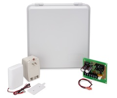
Box Contents
• Takeover Module
• Mounting Plate
• 2 Phillips head screws
• 2 Plastic drywall anchors
PROGRAMMING
The following steps are guidelines for programming (learning) the Super Switch into
the 2GIG Control Panel. Scroll between opons using the ← and → arrows. Move to
the previous or next prompt by pressing the ↑ and ↓ arrows.
1 Select RF sensor #(01 to 48). Assign the Takeover Module to a new zone.
(Terminals 1‐8)
2 Select RF sensor type.
(01) Exit/Entry
(02) Exit/Entry
(03) Perimeter
(04) Interior Follower
3 Select RF equipment type.
4 Select RF sensor equipment code. Enter 0873 for the 2GIG‐TAKE‐345 module.
5 Enter RF sensor serial number (7 digits).
Manual Entry: Type in the last 7‐digit serial number that ends in “1” (XXX‐
XXXX1) that is found on the back of the Super Switch (this is the serial number
for Zone 1).
For each additional zone, add a digit to the end of the serial number. For
example, Zone (terminal) 2 will be (XXX‐XXX2)
Auto Entry: With the panel in Learn‐in mode (press Shift then Learn) trip the
zone that you want to learn in. The correct TX ID should appear. Accept the
correct TX ID by pressing ok.
Remember to press the ↓ arrow to continue through the
system configuration prompts.
6 Select RF sensor equipment age.
(0) new (product is new)
7 Select RF sensor loop number (1).
(1) 1
8 Select RF sensor 1 dialer delay.
(0) disabled
(1) enabled
9 Construct RF sensor descriptor. Press Insert then press any number between
002 and 255 to add a word. For example, if you wanted to name this Takeover
Module as “Wireless Sensor Tool,” press Insert then press 252 for WIRELESS.
Press Insert then press 191 for SENSOR. Press Insert then press 233 for TOOL.
10 Select RF sensor reports (0 to 1).
(0) disabled (sensor does NOT report to the central station)
(1) enabled (sensor reports to the central station)
11 Select RF sensor supervised (0 to 1).
(0) disabled (sensor does NOT report loss of supervision or low battery)
(1) enabled (sensor reports loss of supervision or low battery)
12 Select RF sensor chime (0 to 13).
(0) disabled (panel will not chime when sensor is activated)
(1‐13) enabled (selects a voice and/or chime to sound when sensor is activated)
13 To program another sensor, click next.
14 To exit programming, click skip then end and exit. Upon exit,
the panel takes a few seconds to reset.
FOR UL/ETL Listed Installations use the following equipment:
Altronix (TM) power supply/charger model #AL100UL with an
Altronix (TM) plug‐in transformer, model #TP1620 and a Power
Sonic Model PS‐1212 12 Volt 1.4 Amp Hour rechargeable sealed
lead acid battery or equivalent. See "Using the Altronix Power Supply" on page 3.
Monitoring the Battery
The Super Switch will operate on the connected battery if there is an AC
failure, unless the battery is not capable of supplying enough power.
The Super Switch monitors the battery to ensure it is operational. When
the Super Switch detects a battery voltage below normal level for a
period of time, the Super Switch reports a low battery for each zone (if
programmed in step 11 under Programming).
Testing the Battery Voltage
If you get a “Low Battery” Indicator, do the following:
1 Test the battery’s voltage with a volt reader to ensure that 12 volts are passing
through the switch.
2 If the battery is fine, remove power from the Super Switch (disconnect battery
and AUX power terminal 2).
3 Rewire the Super Switch by connecting the battery first.
4 After the Super Switch is powered by the battery, connect AUX power to
terminal 2 on the Super Switch.
5 Remove power from the Control Panel and then power up the Control Panel. If
everything is connected correctly, the “Low Battery” indicator should disappear.
IMPORTANT: If there is no existing system, then use your own power supply
and group all of the ground wires together and connect them to the
ground port on the Super Switch.
INSTALLING AND MOUNTING
• Screw the mounting bracket to a wall and attach the Super Switch. To release
the bracket, pull up on the tab and slide the bracket down. Mount the bracket
with 2 screws. Mount the Super Switch in RF range of the Control Panel.
To Wire Super Switch with an Existing Power Source
*See Figure 1 on next page
1 Remove AC power from existing wired panel.
2 Remove leads from battery on existing wired panel.
3 With power removed, wire the zones to the Super Switch. Terminals 3‐10 are
marked as Zones 1‐8 on the Super Switch and are where the zones are
connected. For example, to wire zone 1 on the Super Switch take the positive or
HI side of the zone off the existing panel and place it in terminal 3/Zone 1 on
the Super Switch. Leave the negative side or the LO (GND) side of the zone
wired to the existing Control Panel.
4 Repeat this procedure for all zones to be connected to the Super Switch.
TIP: An option is to remove all LO wires from existing panel, group them
together, and connect them to the ground port.
WARNING: THIS IS NOT FOR USE IN A UL/ETL LISTED INSTALLATION.
To Wire Super Switch without an Existing Power Source
See "Using Existing System Wiring" on page 3.
*See Figure 2 on next page
IMPORTANT: Before connecting power to the Super Switch, wire the zones
to the Super Switch. Terminals 3‐10 are marked as Zones 1‐8 on the Super
Switch. For example, to wire zone 1 on the Super Switch take the positive
or HI side of the zone place it in terminal 3/Zone 1 on the Super Switch.
1 Repeat above for all zones to be connected to the Super Switch.
2 Group all LO/(GND) wires together and connect them to terminal 1/G (GND
Port of the Super Switch.
WARNING: DO NOT PLUG THE POWER SUPPLY/CHARGER PLUG‐IN
TRANSFORMER INTO AN OUTLET CONTROLLED BY A SWITCH.
Powering the Super Switch and Other Devices
1 The Super Switch has two wires attached RED (+) and BLACK (‐). Connect the
Red wire to the red terminal and the black wire to the black terminal on the
existing Control Panel’s battery.
2 Connect the wires from the existing Control Panel for the battery into the
spades lugs on top of the wires from the Super Switch that is now connected to
the battery.
3 IF USING AN EXISTING POWER SOURCE: Wire the existing panels AUX power
out to terminal 2/12V port on the Super Switch. If you are using the Super
Switch with PIRs, Glass Break Detectors, or other devices that need power, then
they must receive power from the AUX power on the existing Control Panel.
Reconnect AC power to existing panel.
NOTE: Remove all other devices wired to AUX power on the existing Control
Panel (such as keypads or any other unused devices requiring power).
WARNING: THIS IS NOT FOR USE IN A UL/ETL LISTED INSTALLATION.
2 ©2013 2GIG by Linear Corporation. All Rights Reserved.
Figures 1 and 2
©2013 2GIG by Linear Corporation. All Rights Reserved. 3
Using Existing System Wiring
Using the Altronix Power Supply
4 ©2013 2GIG by Linear Corporation. All Rights Reserved.
Important to Remember
1 All of the zones on the Super Switch are “normally closed” zones.
2 The maximum loop resistance cannot exceed 3K ohms (If the loop resistance
exceeds 3K ohms and the existing panel used end of line resistance, then the
end of line resistor may be removed).
3 Different control panels have different terminals for each zone and aux power.
Please refer to the wiring diagrams that came with the existing panels. For
example, the HI side of Zone 1—Zone 8 on a “Vista” panel is typically terminals
8,11,12,14,15,17,18, and 20. AUX positive is typically terminal 5 on a “Vista”
panel.
WARNING: The Super Switch CANNOT be used to monitor any type of fire
or CO Detection Zones.
Specifications
Regulatory Compliance
This device complies with Part 15 of the FCC's Rules. Operation is
subject to the following two conditions:
1. This device may not cause harmful interference, and
2. This device must accept any interference received, including
interference that may cause undesired operation.
This equipment has been tested and found to comply with the limits
for a Class B digital device, pursuant to Part 15 of the FCC Rules. These
limits are designed to provide reasonable protection against harmful
interference in a residential installation.
This equipment generates, uses and can radiate radio frequency
energy and, if not installed and used in accordance with the
instructions, may cause harmful interference to radio
communications. However, there is no guarantee that interference
will not occur in a particular installation. If this equipment does cause
harmful interference to radio or television reception, which can be
determined by turning the equipment off and on, the user is
encouraged to try to correct the interference by one or more of the
following measures:
• Reorient or relocate the receiving antenna.
• Increase the separation between the equipment and receiver.
• Connect the equipment into an outlet on a circuit different from
that to which the receiver is connected.
• Consult the dealer or an experienced radio/TV technician for help.
This product complies with FCC radiation exposure limits for an
uncontrolled environment. Avoid operating this product at a distance
less than 20 cm from user.
Caution: Any changed or modifications not expressly approved by the
party responsible for compliance could void the user's authority to
operate this equipment.
Limited Warranty
This 2GIG Technologies product is warranted against defects in
material and workmanship for 2 years. This warranty extends only to
wholesale customers who buy direct from 2GIG Technologies or
through 2GIG Technologies’ normal distribution channels. 2GIG
Technologies does not warrant this product to consumers. Consumers
should inquire from their selling dealer as to the nature of the dealer’s
warranty, if any.
There are no obligations or liabilities on the part of 2GIG Technologies
for consequential damages arising out of or in connection with use or
performance of this product or other indirect damages with respect to
loss of property, revenue, or profit, or cost of removal, installation, or
reinstallation. All implied warranties for functionality, are valid only
until the warranty expires. This 2GIG Technologies Warranty is in lieu
of all other warranties expressed or implied.
For technical support in the USA and Canada:
855‐2GIG‐TECH (855‐244‐4832)
Email: techsupport@2gig.com
Internet: dealer.2gig.com
Visit web site for technical support hours of operation
For technical support outside of the USA and Canada:
Contact your regional distributor
Visit dealer.2gig.com for a list of distributors in your region
PN: IPM‐1047‐02 Rev. D
Wireless Signal Range 350 ft, open air, with 2GIG Wireless Control Panel
Code Outputs For each of 8 serialized zones: Fault; Restore;
Tamper; Low Battery
Transmitter Frequency 345.000 MHz (crystal controlled)
Transmitter Frequency
Tolerance
±15kHz
Transmitter Bandwidth 24kHz
Modulation Type Amplitude Shift Keying‐On/Off Keying (ASK‐OOK)
Unique ID Codes Over one million different code combinations
Supervisory Interval 70 minutes
Peak Field Strength Typical 50,000 uV/m at 3m
Sensor Dimensions (LxWxH) 3.54 x 2.56 x 1.13 in. (9.0 x 6.5 x 2.9 cm)
Weight (including bracket) 2.85 oz. (80.8 g)
Housing Material ABS plastic
Color White
Operating Temperature Limits 32° to 120° F (0° to 49° C)
Relative Humidity 5‐95% Non‐Condensing
Operating Voltage 9‐16 volts DC, 50mA
Included Accessories Mounting plate, 2 Phillip’s head screws, 2 plastic
drywall anchors
- Uploaded