Alarm.com ADC-SEM210-VT - Install Guide
Related Products

Related Categories
Document Transcript
SYSTEM
ENHANCEMENT
MODULE
Honeywell/ADEMCO VISTA®
INSTALLATION GUIDE
INSTALL WIZARD AVAILABLE AT
ALARM.COM/SEMVISTA
DUAL PATH 2
EQUIPMENT
TOOLS AND SUPPLIES NEEDED
•
Small blade screwdriver and Phillips screwdriver
•
Drill and bits for screws and/or wall anchors
•
Four-conductor, 22-gauge or larger stranded wire
•
Alpha keypad
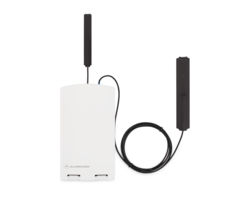
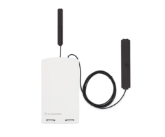
OVERVIEW
The System Enhancement Module (SEM) can be used with
Honeywell/ADEMCO VISTA-10P, VISTA-15P, and VISTA-20P
panels to
enable wireless reporting of alarms and other system events over the
wireless cellular network and optional broadband Ethernet. The SEM
is intended to be used as the primary communication path for all alarm
signaling to the central monitoring station. The wireless alarm signaling
and routing service is operated by Alarm.com. The SEM also features
integrated support for Alarm.com’s home automation services with
built-in Z-Wave capabilities.
Alarm.com strongly recommends installing an alpha keypad with at least 32
zones to ensure the “Communication Failure” trouble condition is displayed to
the user. See FAQs for more information.
WALL ANCHORS
SCREWS
ETHERNET ADAPTER
WIRE AND FUSE
SYSTEM
ENHANCEMENT
MODULE 3
TABLE OF CONTENTS
Step 1:
Verify Panel Compatibility
....................................
4
Step 2:
Create an Account
..................................................
5
Step 3:
Enable Keypad Address
.........................................
6
Step 4:
Disconnect Power from Panel
.............................
7
Step 5:
Mount the SEM
........................................................
8
Step 6:
Wire the SEM to the VISTA Panel
.......................
9
Step 7:
Power Up the Panel
.................................................
10
Add & Delete Z-Wave Devices
...................................................
11
Touchscreen Keypads
...................................................................
14
Panel Settings
................................................................................
15
LEDs
.................................................................................................
16
FAQs
.................................................................................................
19
Troubleshooting
.............................................................................
21
Specifications
................................................................................
22
Regulatory Information
..............................................................
23
SEM Quick Tips
..............................................................................
24 4
STEP 1:
VERIFY PANEL COMPATIBILITY
The SEM is compatible with
Honeywell/ADEMCO VISTA-10P, -15P, and
-20P
panels and the equivalents below, dating back to
2005
. The date
will be printed on the chip inside the panel as shown below.
Honeywell/ADEMCO
VISTA-10P
Honeywell/ADEMCO VISTA-10PSIA
First Alert FA130CP
First Alert FA130CPSIA
Honeywell/ADEMCO
VISTA-15P
Honeywell/ADEMCO VISTA-15PSIA
First Alert FA148CP
First Alert FA148CPSIA
Honeywell/ADEMCO
VISTA-20P
Honeywell/ADEMCO VISTA-20PSIA
First Alert FA168CPS
First Alert FA168CPSSIA
Please see the Alarm.com Partner Portal Knowledge Base
(
www.alarm.com/dealer
) for the most up to date list of compatible panels.
TOUCHSCREEN KEYPADS
Touchscreen keypad compatibility details can be found on
page 14
.
Some system changes will not be processed by Alarm.com
unless the touchscreen keypad is used in Console Mode.
The SEM is not compatible with POTS. The SEM should
be the only communication path for alarm signaling to
the central station. 5
STEP 2:
CREATE AN ACCOUNT
Before installing the SEM, first create a new Alarm.com customer account.
We recommend creating the account at least 24 hours prior to installation.
This will ensure that the SEM is activated prior to installation. To create an
account go to the Alarm.com Partner Portal or MobileTech and log in. You
will need the following information to create the account:
•
Customer Address
•
Customer Phone Number
•
Customer Email Address
•
Preferred Login Name for the Customer
•
Alarm.com Module Serial Number
•
Existing Panel Installer Code
During
Step 4
of the “Create New Customer” process, you will be prompted
to enter the
current Installer Code
on the panel. Alarm.com will use this
code to access panel programming and read information stored on the
panel.
At the end of the “Create New Customer” process, you will be able
to print or email a Welcome Letter for the customer, which includes
login information for the Alarm.com Customer Website. 6
STEP 3:
ENABLE KEYPAD ADDRESS
ENABLING KEYPAD 8 DEVICE ADDRESS 23
The SEM communicates with the VISTA panel as if it is a keypad.
By default, the SEM will use
Keypad 8 Device Address 23
to
communicate. Address 23 must be enabled via panel programming.
To do this, enter programming and select
*196 + [1] + *99
at the keypad.
IF ADDRESS 23 IS ALREADY IN USE
In most cases, Address 23 will be available. If another keypad is already
connected to Address 23, you will need to manually select a different
keypad address. You can do this by using the DIP switches on the SEM,
as pictured below.
1.
Identify an available keypad address.
2.
Using the chart below, change the DIP switches on
the SEM to match the corresponding keypad address.
3.
Enable the address by entering the corresponding
VISTA programming command at the panel.
If the correct keypad address is not enabled, repeated
reports of Panel Malfunction will be shown in the Event
History on the Partner Portal or MobileTech once the
SEM is powered on and connects to the network.
Keypad
Address
DIP Switch
Setting
VIS TA
Programming Menu
17
None—all OFF
*190
18
Switch 4 ON, others OFF
*191
19
Switch 3 ON, others OFF
*192
20
Switch 3 and 4 ON, others OFF
*193
21
Switch 2 ON, others OFF
*194
22
Switch 2 and 4 ON, others OFF
*195
23
Switch 2 and 3 ON, others OFF
*196 7
STEP 4:
DISCONNECT POWER FROM PANEL
Prior to disconnecting power from the panel, first verify that the
panel is disarmed. Next, remove panel AC Power and disconnect the
backup battery.
This is necessary to prevent damaging the panel
or module while making wiring connections. 8
STEP 5:
MOUNT THE SEM
You must be free of static electricity before handling electronic
components. Touch a grounded metal surface before touching
the circuit board.
Press down on the bottom tabs of the enclosure cover to remove it
and set it aside.
Carefully remove the SEM circuit board by depressing the interior
bottom tab.
Place the SEM back plate on the wall at the desired mounting
location and mark the three mounting holes as shown below.
Set the back plate aside and drill holes at the mounting locations.
Use wall anchors where studs are not present and secure the back
plate to the wall with the enclosed screws.
Insert the SEM circuit board back into the back plate. 9
STEP 6:
WIRE THE SEM TO THE VISTA PANEL
Verify panel AC Power is removed and
the backup battery is disconnected.
•
Connect panel terminal 4 (GND) to SEM GND.
•
Connect panel terminal 6 (
GREEN: DATA IN FROM KEYPAD
)
to
GREEN
(
OUT
)
.
•
Connect panel terminal 7 (
YELLOW: KEYPAD DATA OUT
)
to
YELLOW
(
IN
).
•
Use the included red cable with the two prong battery connector
to connect the battery to both the SEM and the panel. For a power-
limited circuit, ensure the fuse is inside the VISTA panel.
Once wiring is complete, route the antenna(s) outside of the enclosure,
away from the SEM, and replace the enclosure cover.
Please note that
the antenna(s) should be routed through the second and third channel
openings at the top of the enclosure (see zoom view below).
12V Battery
VISTA Panel
GND
4
5
+12V
GREEN
(
DATA IN
)
YELLOW
(
DATA OUT
)
6
7
SEM
+12V
YELLOW
(
IN
)
GREEN
(
OUT
)
GND
CDMA/HSPA
Modules
LTE Modules 10
The zone scan will automatically begin after the panel is powered up.
On the keypad you will see a series of disarms and programming setting
changes before seeing “MODEM COMM” on the screen.
STEP 7:
POWER UP THE PANEL
Connect the backup battery and restore AC power to the panel.
For the SEM to interact with the existing zones on the system, it must
read them from the VISTA panel. The SEM will do a “zone scan” to read
this information.
Additionally, the SEM will automatically set the panel settings needed
for the SEM to communicate. These settings can be found on
page 15
.
ZONE SCAN
~ 3 minutes
Do not touch the panel or keypad.
When the zone scan is complete the keypad will display the home screen.
This process will take less than 3 minutes.
Now that the zone scan is complete, the Equipment list should be updated
on the Partner Portal and the Installer and Master User codes should be
synced with the SEM.
ZONE SCAN
COMPLETE
Ready to Arm
If you do not see the MODEM COMM message appear on the
keypad during zone scan and instead notice the keypad scrolling
through each zone individually, the SEM is using an alternate
zone scan method. Wait for the SEM to finish scanning and
leave programming before interacting with the panel. Resync
the panel master code with the SEM by changing the Master
Code at the panel or through the Customer Website.
DUAL PATH (OPTIONAL)
For Broadband Ethernet,
connect the provided Ethernet
Dongle to the connector on the SEM.
Connect the Ethernet cable to the
provided Ethernet Dongle. 11
ADD & DELETE Z-WAVE DEVICES
Please visit the Alarm.com Knowledge Base for a complete explanation
of Z-Wave communication, Z-Wave signal strength,
and additional installation resources.
Alarm.com will not recognize any Z-Wave devices previously learned into
the panel. These devices will need to be deleted from the previous Z-Wave
network and added to the SEM for the customer to use Alarm.com’s
home automation services (for example, automation control using the
Customer Website, Mobile App, and intelligent automation rules).
If the customer is on a different interactive platform,
we recommend having them log in to that site and taking
screenshots of notifications, rules, and home automation
device names for reference later.
ADDING Z-WAVE DEVICES
Using the Partner Portal or MobileTech is strongly recommended.
To add Z-Wave devices using MobileTech:
1.
Move all Z-Wave devices to their final location on the property.
2.
Log in to MobileTech.
3.
Find the customer account.
4.
Tap
Equipment
.
5.
Tap
Z-Wave Devices
.
6.
Tap to expand
Z-Wave Actions
.
7.
Tap
Add Z-Wave Devices
.
8.
Wait for the bolded message:
Checking for new devices on the
network.
9.
Trigger a device to add it to the network.
10.
When a device is added successfully, it shows up on this screen
following a 30-second delay.
11.
Continue triggering devices. You may add several devices to the
network without re-entering Add Mode.
To add Z-Wave devices using the Partner Portal:
1.
Move all Z-Wave devices to their final location on the property.
2.
Log in to the Partner Portal.
3.
Find the customer account.
4.
Click
Equipment
.
5.
Click the
emPower Devices tab
.
6.
Click
Add Z-Wave Devices
.
7.
Wait for the bolded message:
Checking for new devices on the
network.
8.
Trigger a device to add it to the network.
9.
When a device is added successfully, it shows up on this screen
following a 30-second delay.
10.
Continue triggering devices. You may add several devices to the
network without re-entering Add Mode.
TIP: 12
To add Z-Wave devices using the SEM:
1.
Press and hold the Z-Wave button on the Alarm.com module.
2.
Release the button after LED L5 flashes in groups of four. L2 also
flashes.
3.
Trigger a device to add it to the network.
4.
When a device is added successfully, L5 illuminates solid.
5.
You need to re-enter Add Mode before triggering the next device.
DELETING Z-WAVE DEVICES
Using the Partner Portal or MobileTech is strongly recommended.
To delete Z-Wave devices using MobileTech:
1.
Log in to MobileTech.
2.
Find the customer account.
3.
Tap
Equipment
.
4.
Tap
Z-Wave Devices
.
5.
Tap to expand
Z-Wave Actions
.
6.
Tap
Delete Z-Wave Devices
.
7.
Wait for the bolded message:
Checking for deleted devices on the
network.
8.
Trigger a device to delete it from the network.
9.
When a device is deleted successfully, and its network data is
erased, it will show up on this screen following a 30-second
delay.
10.
Continue triggering devices. You may delete several devices
from the network without re-entering Delete Mode.
If you cannot add a device to the network, you may need to
delete the device’s current network data using the device
deletion process before you can add it to the new network
(some devices come from the factory with network data).
TIP: 13
To delete Z-Wave devices using the Partner Portal:
1.
Log in to the Partner Portal.
2.
Find the customer account.
3.
Click
Equipment
.
4.
Click the
emPower Devices tab
.
5.
Click
Delete Z-Wave Devices
.
6.
Wait for the bolded message:
Checking for deleted devices on the
network.
7.
Trigger a device to delete it from the network.
8.
When a device is deleted successfully, and its network data is
erased, it will show up on this screen following a 30-second
delay.
9.
Continue triggering devices. You may delete several devices
from the network without re-entering Delete Mode.
To delete Z-Wave devices using the SEM:
1.
Press and hold the Z-Wave button on the Alarm.com module.
2.
Release the button after LED L5 flashes in groups of two. L2 also
flashes.
3.
Press and hold the Z-Wave button on the module a second time.
4.
Release the Z-Wave button after LED L5 flashes in groups of two.
5.
Trigger a device to erase its network data and delete it from the
network.
6.
When a device is deleted successfully, L5 illuminates solid.
7.
You need to re-enter Delete Mode before triggering the next device. 14
TOUCHSCREEN KEYPADS
The SEM is compatible with AUI devices, including the 6280, Tuxedo Touch,
and other touchscreen keypads. Arming, disarming, panics, and alarms
initiated on these keypads will be processed by Alarm.com and reported to
the central station. However, the following activity will not be processed by
Alarm.com
unless the keypad is used in Console Mode
.
•
Changing the Installer Code via Quick Programming mode
•
Bypassing open sensors
•
The specific user that armed or disarmed the system
Please note that the SEM supports Z-Wave automation via Alarm.com
only. This means that customers using the Tuxedo Touch to control their
Z-Wave devices will need to choose whether to continue using the Tuxedo
Touch for Z-Wave automation, or whether to switch to Alarm.com
(for example, automation control using the Customer Website, Mobile
App, and intelligent automation rules). If the customer chooses to
switch to Alarm.com Z-Wave control, all of the Z-Wave devices will need
to be deleted from the Tuxedo Touch and learned into to the SEM.
Even if customers choose not to switch to Alarm.com for Z-Wave
automation, they will still be able to enjoy access to video, garage door
automation, and Lutron lighting control in addition to interactive security
with Alarm.com. 15
TIP:
PANEL SETTINGS
For the SEM to communicate with the panel and report all alarms,
the following VISTA settings need to be set at the panel. These settings
are automatically changed during first power up after account creation so
no further action should need to be taken. Here is a list of the automatic
programming changes, for reference.
ENABLE IP/GSM
*29 IP/GSM needs to be set to [1]. This will ensure that the panel
is communicating with the SEM.
SILENT ALARMS
For the SEM to report silent and duress alarms, the following VISTA
settings are automatically changed at the panel.
•
*41 Primary Phone No. needs to be cleared.
•
*42 Secondary Phone No. needs to be cleared.
•
*43 Partition 1 Primary Acct. No. needs to be set to a four-digit
number. Alarm.com automatically set this setting to 1234.
•
*45 Partition 2 Primary Acct. No. needs to be set to a four-digit
number. Alarm.com automatically set this setting to 4321.
•
*48 Report Format needs the primary phone number format
set to [77].
•
*55 Dynamic Signaling Priority needs to be set to [1].
•
*64 Test Report Code needs to be set to [1,0].
•
*92 Phone Line Monitor Enable needs to be set to [0,0].
•
The Zone 92 reporting code needs to be enabled for duress reporting.
The customer’s actual Central Station Forwarding Settings
should be set up on the Alarm.com Partner Portal.
BYPASS OPEN SENSORS
Before the customer can use the bypass open sensors feature on the
Customer Website or Mobile App, *23 Quick (Forced) Bypass needs to
be enabled.
This setting is not automatically enabled. If the customer
would like to use this feature on the Customer Site or Mobile App,
please enable this setting. 16
LED
s
The Alarm.com Module LEDs can be used to indicate communication
errors, panel communication, network communication, and signal strength.
LED
FUNCTION
L1
Error LED: L1 will flash 1 to 8 times in a four-second interval
to indicate specific error conditions such as a network error,
panel communication error, or radio error.
L2
Panel communication LED: L2 flashes every time a data
packet is received from the panel.
L3
Cellular communication LED: L3 flashes every time a data
packet is received from the cellular radio.
L4
Cellular signal level LED: L4 flashes 0 to 5 times indicating
the cellular signal strength, or toggles on/of f when
communicating with the Alarm.com servers.
L5
Z-Wave Error LED: Visit the Knowledge Base on the Partner
Portal or MobileTech for additional Z-Wave installation
resources.
L6
Reserved for future use.
L7
Reserved for future use.
LED L1 (RED)
L1 flashes when an error is encountered. The number of flashes indicates
the error number. If there are two or more errors at the same time, the
errors will flash one after the other. The LED will stay off for at least four
seconds between errors.
NUMBER OF LED L1 ERROR DESCRIPTIONS
AND SOLUTION FLASHES
1
Alarm.com module cannot communicate with the panel.
Perform a power cycle on the panel. If the error persists
lift the Alarm.com module out of the SEM circuit board and
re-insert it while power is disconnected from the system.
2 then 4
The Alarm.com module provisioning process could not be
completed. If the error persists, power cycle the system,
then contact Technical Support.
2 then 5
The Alarm.com module provisioning process could not be
completed because the module is currently roaming off the
carrier’s primary network.
BOTTOM OF ALARM.COM MODULE
System
Enhancement
Module (SEM)
1
2 17
TIP:
3
The Alarm.com module is trying to register on the cellular
network. If it persists for more than a few minutes, the
module is having problems registering. Check L4 for signal
level. If signal level is lower than 2 bars, change the panel’s
location or use a remote antenna option.
4
The Alarm.com module is registered on the cellular network
but could not connect with Alarm.com. Contact Alarm.com
Technical Support.
5
The radio on the module is not working correctly. If this persists
for more than a few minutes the module may need to be
replaced. This error is extremely rare, so please verify that the
module is flashing 5 times.
6
This indicates an error only if it persists for more than a
minute. Otherwise, it’s an indication that the module is
resolving an unusual condition regarding communication
with the cellular network.
7
The SEM is unable to access panel programming.
Check panel wiring and Installer Code.
8
If this error persists, the account may have been set up
incorrectly. Check that the serial number being used matches
the serial number used to create the account. If the serial
numbers are the same, contact Technical Support.
LED L2 (YELLOW)
L2 flashes with every communication between the SEM and the panel.
The normal pattern calls for a series of quick flashes every two seconds
when the Alarm.com module is in Idle mode or four seconds in PowerSave
mode. See Alarm.com Module States (modes) for an explanation of the
three modes.
L2 also occasionally flashes in patterns to indicate Z-Wave status,
when the SEM is being used to add or remove Z-Wave devices.
LED L3 (GREEN OR YELLOW)
L3 flashes with every communication between the SEM and its radio unit
in Idle mode, and with every communication with Alarm.com in Connected
mode. In PowerSave mode this LED flashes in unison with LED L2.
LED L4 (GREEN OR YELLOW)
L4 indicates the cellular signal level as a number of flashes (0 to 5 bars).
The number of bars may not correspond to the number of bars shown
on your cell phone. A level of 5 bars is obtained only in the strongest
signal conditions. Signal level is updated every ten seconds if it fluctuates,
or every 30 seconds if it is fairly stable.
If LED L4 is continuously flashing, the module provisioning process is
in progress. LED L4 will begin flashing to indicate signal level as soon
as the provisioning process is complete.
If LED L4 is not flashing, this means one of the following:
•
The Alarm.com module is in PowerSave mode
•
The Alarm.com module just powered up
•
There is no cellular coverage in the area
In Connected mode, LED L4 toggles on and off.
Alarm.com recommends a steady signal level of two
or higher for proper operation of the SEM.
18
LED L5 (YELLOW)
L5 indicates Z-Wave errors. If you can’t add a device to the network, try
deleting the device and re-adding it to the network. Contact Alarm.com
Technical Support with additional issues.
ALARM.COM MODULE STATES (MODES)
There are three Alarm.com module states (modes).
Idle Mode
In Idle mode, the AC power is up, the battery level is greater than 11.5
volts, and the SEM is not currently connected to the Alarm.com servers.
This is normal for the SEM and is the most common state.
L1
Flashes errors, if any
L2
Communication with panel
L3
Communication with radio unit
L4
Signal level (0 to 5 bars)
L5
Flashes errors, if any
PowerSave Mode
In PowerSave mode, the module just powered up, AC power is down, or
battery level is less than 11.5 volts. The radio part of the SEM draws 10 mA
in PowerSave mode. It is fully functional and will go into Connected mode
as soon as a signal needs to be sent. Performing an Alarm.com phone test
will switch the module into Idle mode and update the signal level reading.
L1
Inactive
L2
Communication with panel
L3
Same flashing pattern as L2
L4
Inactive
L5
Inactive
Connected Mode
In Connected mode, the SEM is connected to the Alarm.com servers and
reported an alarm or other condition. The module stays in Connected mode
for at least six minutes after the last message is exchanged. Entering
Installer programming will cause the SEM to go into Idle mode.
L1
Flashes errors, if any
L2
Communication with panel
L3
Communication with Alarm.com
L4
Alternates two seconds on, then two seconds off
L5
Inactive 19
FREQUENTLY ASKED QUESTIONS
Will the customer be notified if the panel fails to communicate
with Alarm.com?
The SEM displays a Check 103 LRR message locally at the panel
immediately when a failure to communicate (FTC) condition arises.
During the FTC event, all events will still be picked up as normal by the
SEM. To clear the message, the user must disarm the panel twice. If
the FTC event is not over after clearing (disarming twice), the trouble
condition will be re-issued at the next supervised event.
How should I choose the best location to install the SEM?
•
Check the signal strength before choosing a final location. Perform a
walking signal strength test by powering the SEM using the battery
directly (connect the GND and +12V terminals). After two minutes,
cellular signal level LED L4 will flash between one and five times to
indicate the signal strength (where five is the strongest signal).
Alarm.com recommends a signal level of two or higher for proper
operation of the SEM.
•
Avoid mounting the SEM in areas with excessive metal or
electrical wiring, such as furnace or utility rooms.
•
Mount the module near an outside wall, preferably on an
upper level.
•
Do not mount the SEM inside of the panel’s metal box. Doing so
will negatively impact Z-Wave performance.
•
For homes or businesses located in canyons or with hills nearby,
it may be necessary to place the antenna higher in the building.
•
If the SEM location requires a longer power cable, splice the provided
power wire with the fuse to your wire and leave the fuse inside the
VISTA panel enclosure.
Why do I need to enter the Installer Code during account creation?
The Installer Code entered during account creation (
see Step 2
) will
be used to access and read the zones currently learned into the panel.
The Installer Code can be changed after the zone scan is complete.
How do I initiate or test communication between the
SEM and Alarm.com?
Perform an Alarm.com phone test by pressing
[#] + [9] + [8] + [7] + [*]
.
This phone test will not be viewable on the keypad but can be verified
on the Partner Portal or MobileTech Event History.
Is the SEM compatible with the VISTA-21iP?
The SEM is compatible with the 21iP, if the Internal IP/GSM Jumper
is set in the OFF position.
OFF
position 20
Does the SEM support reporting multiple alarms on a single zone
(Swinger Suppression *93)?
The SEM will only report one instance of each alarm per alarm event
regardless of the settings specified on the panel in the *93 programming
menu. The SEM does not support reporting multiple alarms on a
single zone.
Is the SEM compatible with POTS?
No, the SEM should be the only communication path for alarm signaling
to the central station.
How does SEM handle dialer delay?
The SEM uses the Dialer Delay value that is stored in the panel. This value
can be changed using the Partner Portal, MobileTech, or on the panel in
programming section *50.
Is the SEM compatible with Honeywell’s Street Smart Series
Code Encryptors?
Yes, the SEM is compatible with Honeywell’s Street Smart Series
Code Encryptors. As with other touchscreen keypads or AUI devices on
a system with a Code Encryptor, the following steps will need to be
followed to install the SEM.
1.
Disconnect power from the panel.
2.
Disconnect the touchscreen keypad or AUI device from
the panel.
3.
Install the SEM, following the SEM installation steps
(without the touchscreen keypad or AUI device connected).
4.
Once the SEM is installed and working properly, power down
the system.
5.
Reconnect the touchscreen keypad or AUI device.
6.
Restore power to the panel and SEM.
Does the SEM support multiple partitions?
The SEM does support partitions. The panel can have up to the maximum
number of partitions the panel supports; however, zones are not supported
throughout all partitions. Zones should only be enrolled in a single partition.
Zones in multiple partitions are not supported by the SEM.
Can I can add and delete sensors remotely?
Yes, sensors can be added, changed, or deleted using MobileTech or the
Remote Toolkit on the Partner Portal.
Are the additional terminals on the SEM circuit board used or
needed for the install?
No, these terminals are for future development. Please disregard the relay,
zone, ring, and tip terminals on the SEM circuit board.
Does the SEM support Cross Zones?
No, the SEM does not support the Cross Zone attribute. The SEM will not
report the Cross Zone event to the central station. 21
TROUBLESHOOTING
Arming with the Alarm.com App or Customer Website isn’t working
If you are unable to arm your system remotely, please change the Master
User Code locally to a code of your choosing and then change it back to
your desired Master User Code.
The Equipment List is empty on the Partner Portal or MobileTech
If the Equipment List is not showing on the Partner Portal or MobileTech
and the SEM failed to do a zone scan when initially powered on, verify that:
•
The correct keypad address is enabled
•
All wiring is correct
•
The Installer Code is synced (if the Installer Code is out of sync you can
change it locally at the panel and power cycle).
•
The panel is disarmed, and select Get Equipment List on the
Partner Portal or power cycle the panel
The SEM is failing to zone scan and the Event History shows
several Panel Malfunction error messages
Verify the Keypad Address is enabled correctly.
See Step 3
.
None of the LEDs on the SEM are ON.
Remove power from the panel and verify that all wiring is correct.
My panel changed from ARM AWAY to ARM STAY automatically.
Auto Arm Stay is enabled by default on the VISTA panel. If enabled,
the panel will change from ARM AWAY to ARM STAY if a sensor is not
opened and closed during the exit delay. This arming status will then
be updated on the Customer Website and Mobile App. This setting can
be disabled using the Partner Portal, MobileTech, or on the panel in
programming section *84 (select [0] to disable or [1] to enable).
The panel continues to send alarm notifications after disarming locally.
To clear a stored alarm from memory the panel must be disarmed
twice. If alarm notifications are continually received from a panel in
disarm state, disarm again locally at the panel or from the Mobile App.
My keypad will occasionally display “MODEM COMM”.
The keypad may display “MODEM COMM” for brief moments while
interacting with the SEM. This is normal and expected behavior.
Are both communication pathways (cellular and broadband)
required?
We recommend using both the cellular and broadband connections.
However, if broadband is disabled the SEM will continue to communicate
using cellular. 22
SPECIFICATIONS
Compatibility
Honeywell/ADEMCO VISTA-10P, VISTA-15P
and VISTA-20P (Please visit alarm.com/
dealer for a full list of supported panels and
compatibility information)
Power
Requirements
12V nominal, 130mA (continuous) 2000mA
(instantaneous peaks) maximum
(from panel battery)
Cellular Network
Dual Band CDMA (3G), Dual Band HSPA (3G),
or Dual Band LTE (4G)
Panel Interfaces
One ECP three 2-terminal keypad bus
12V power and ground to panel battery
Alarm.com
Module Indicators
One module/panel communication status
LED, one module power LED, one automation
LED, three wireless communication status
LEDs
SEM Circuit
Board Indicators
One LAN LED, one processor LED,
one COMM fail LED
Operating
Temperature
32 to 120°F (0 to 49°C)
Storage
Temperature
-30 to 140°F (-34 to 60°C)
Humidity
90% relative humidity non-condensing
Enclosure
Dimensions
(L x W x D) 7.5 x 4.25 x 1.5 in. (19.05 x 11.43 x
3.81 cm)
Enclosure Color
White
Case Material
High-impact, ABS plastic
Listings
FCC part 15, Verizon Certified 23
REGULATORY INFORMATION
Changes or modifications not expressly approved by Alarm.com
can void the user’s authority to operate the equipment.
This equipment has been tested and found to comply with the limits
for a Class B digital device, pursuant to part 15 of the FCC Rules. These
limits are designed to provide reasonable protection against harmful
interference in a residential installation. This equipment generates,
uses, and can radiate radio frequency energy and, if not installed and
used in accordance with the instructions, may cause harmful interference
to radio communications. However, there is no guarantee that
interference will not occur in a particular installation. If this equipment
does cause harmful interference to radio or television reception, which
can be determined by turning the equipment off and on, the user is
encouraged to try to correct the interference by one or more of the
following measures:
•
Reorient or relocate the receiving antenna.
•
Increase the separation between the equipment and receiver.
•
Connect the equipment into an outlet on a circuit different form that
which the receiver is connected.
•
Consult the dealer or an experienced radio/TV technician for help.
Operation is subject to the following two conditions:
1.
This device may not cause interference.
2.
This device must accept any interference, including interference
that may cause undesired operation of the device.
This equipment complies with the FCC RF radiation exposure limits
set forth for an uncontrolled environment. This equipment should be
installed and operated with a minimum distance of 20 centimeters
between the radiator and your body.
IC REGULATIONS
Contains Model:
This device complies with Industry Canada license-exempt RSS
standard(s). Operation is subject to the following two conditions: (1) this
device may not cause interference, and (2) this device must accept any
interference, including interference that may cause undesired operation
of the device.
Le présent appareil est conforme aux CNR d’Industrie Canada
applicables aux appareils radio exempts de licence. L’exploitation est
autorisée aux deux conditions suivantes : (1) l’appareil ne doit pas
produire de brouillage, et (2) l’utilisateur de l’appareil doit accepter tout
brouillage radioélectrique subi, même si le brouillage est susceptible d’en
compromettre le fonctionnement. SET KEYPAD ADDRESS
Ensure the SEM’s keypad address is enabled in VISTA
programming. The default keypad address is 23 enabled
in *196 VISTA programming.
See Step 3
for additional addresses and their
corresponding programming sections.
WIRING IS CORRECT
•
[PANEL] GREEN DATA IN
[SEM] GREEN (OUT)
•
[PANEL] YELLOW DATA OUT
[SEM] YELLOW (IN)
•
SEM is powered from 12V battery with included
connector and fuse
INSTALLER CODE SYNCED WITH SEM
The Installer Code entered during account creation is
applied to the SEM during the initialization process.
If the system still fails to initiate a zone scan, set the
Installer Code to a new value and power cycle.
If the customer has existing Z-Wave devices, they will
need to be deleted from the previous controller and
added to the SEM. Tuxedo Touch users will need to choose
between leaving devices enrolled on the Tuxedo for local
control or enrolling them on the SEM to enable remote
control capability.
CONTACT INFORMATION
If you’ve completed the steps above, but are experiencing difficulties with
SEM installation, please visit www.alarm.com/supportcenter or contact
Alarm.com Technical Support at
866-834-0470
and we’ll be happy to
assist you further.
SEM INSTALLATION GUIDE 181005
|
Copyright © 2018 Alarm.com. All rights reserved.
1
2
3
Z-WAV E
SEM QUICK TIPS
- Uploaded