Honeywell 5800C2W Installation Manual - Original


Hi Todd, As the C2W transformer is the same size as a Lynx Touch/Lyric Transformer, but the dimensions for the C2W Transformer is 3 1/2 inches long, 2 inches wide and 3 1/2 high. I hope this helps and if you need further assistance please let us know
How wide is the transformer? From what I've read you can use more than one 5800c2w (I'm thinking I need two even grouping window sensors for each room) but I'm looking for a nice and tidy install and wondering if I need to add another outlet where I have a single gang and would they fit side by side or should I try to put one upside down above the other. I don't think you would be able to use the screw fastener to make sure they don't fall out then. Recommendations?
Send your request to support@alarmgrid.com so that we can work with you in depth to find the equipment that you'll need. The 5800C2W can occupy 9 zones in system programming, and you can program as many 5800C2Ws as the system can support. As long as there are open zones, you can add more. The 5828 works with the 5800 wireless protocol.
Hello, I just moved into a home that has an older hard wired security system. I am trying to upgrade an older Vista 20 or ADEMCO 4110XM system to one that provides Z-Wave,IP wireless and cellular. My current plan is to buy a 7000 and use that as my main panel. Use multiple 5800C2W devices to convert the current 34 home run hard wired sensors to wireless (2 wire and motion sensors only). I would need 4 of them. How many 5800C2W can be installed in a 5200 or 7000 system? I will be buying wireless new smokes since it is not recommended to wire these to the 5800C2W The current wiiring has 34 home run wires. In man cases,similar sensors, like a bank of 3 windows, are tied together and then use one zone on the 20. I don't think this has ever worked and why I want to break each zone out by itself. The cost of the 5800C2W will be less than buying all new 5800 sensors. I understand to add keypads, I wojld need the 5828 (V) which are wireless. Do they communicate on the Home Wifi or the 5800 network? The reason I aks is that I may want a keypad in my hanger which will be on my Wifi (possibly with a repeater) but maybe not within reach of the 5800 nework.
Can you send pictures of the panel wiring to support@alarmgrid.com, please also confirm if you have 10 zones in use or if you're using just the 5.
Ok so the tamper circuits are for rthese boxes in the attached picture that are at every window / door, it seems opening them will open the tamper circuit. Has anyone seen a set up like this before? I’m becoming ever disheartened it’s not compatible with the c2w https://uploads.disquscdn.com/images/f2fd7d9c9fdad7ab41d4097fb6d8dbed1e7b62cc524852d5a02ff2e33faf70ad.jpg
My old alarm has 5 zones but beside the terminals for each zone there are tamper wires connected to terminals so my set up is Zone 1 (2 wires) Tamper 1 (2 wires) etc all the way up to 5, does anyone know of this can be wired to the 5800
Well they will have more oversight on your programming than we do. Normally you should go to them for tech support. If you are unable to troubleshoot things and they deem the product as faulty we can do a final round of troubleshooting before issuing a warranty replacement.
Thanks - well i didn't think of reaching out to them since i purchased the equipment from Alarm grid.
It's hard to say why that would have been happening at this time but every C2W should have the magnet installed in the cover and the cover on properly to function properly. Was your existing monitoring company not able to provide you the technical support to solve that problem?
OK well it's been 12 hours and so far so good. When I first had this installed I had the fault issue within 6 hours when I had something on zone 1. I deleted it and then had the same issue on zone 2 about 1 week later. Hopefully we are all good now. Is it odd that the second fault didn't report/have issue until a week later?
No. You have an alarm panel of some type, which may or may not have hardwired zones of its own, then you have the 5800C2W, which has 9 wired zone inputs. When I mentioned Zone 1, I was talking about the Zone 1 input on the 5800C2W, not Zone 1 on the alarm panel. Whichever zone on your panel is programmed with the first serial number of the 5800C2W will handle all the supervision for the 5800C2W module, including tamper, AC Loss, and Low Battery. Let's assume you used the zone 1 input on the C2W, and it's programmed on Panel Zone 2. If the 5800C2W has a tamper fault, or a low battery, this is going to be reported on the panel as a tamper or low battery on panel zone 2 (5800C2W input zone 1). If it's reporting tamper on a zone that originates from the 5800C2W, then it has to think the tamper is faulted on the unit. Pull the cover off, verify the magnet is still properly installed in the correct place in the cover, then replace the lid and disarm twice to see if the issue clears. If it does not, then you should contact whomever did your installation and get them to check it.
The c2w reports its issues on Zone 2 along with the window in that zone? So should I program the module into the Lyric? The serial number ends with Zero for the module and then 1(zone one), 2( zone two) etc. I do not have anything on Zone 1 for now. For about a week everything was fine until a few days ago.
The tamper will follow the first programmed zone used by the C2W as the C2W reports C2W issues (power loss, low battery and tamper) on that first programmed zone. Once you have the magnet installed in the cover and the cover on the C2W, you should not still have any of your wired zones going through the C2W reporting a tamper.
Report back here after you have the tamper magnet installed and the cover fully snapped shut. You should be able to properly fault those zones and the tamper trouble should go away. You cannot tamper a wired contact. This must be the tamper on the C2W and it always reports on the first programmed zone.
I will try this but the sunroom windows are on Zone 2. I dont have anything on Zone 1 at all. I actually had my dining room window on Zone 1 and had this exact same issue. So i deleted it from Zone 1 and left it empty. Now i have the same issue on my Zone 2 (sunroom window group of 5 windows).
I recommend installing the tamper magnet inside the C2W's cover. Then closing it up and clearing the tamper troubles by pressing the home key until you get a number pad. Then enter you master code. You may need to do this a couple times to clear the troubles. Even though it is zone 8 on the alarm system I am guessing the sunroom windows are still technically the first zone on the C2W itself. The tamper magnet will fix this.
I did not install the tamper on the module. The actual module is not installed in my Honeywell Lyric. I had it there before but thought that was the issue and deleted it(i have this issue with and without it in my panel). All of my other senors work perfectly fine. Its just this Zone 8 ( which is my sunroom window group) that getting triggered every once in a while for no reason. It gets triggered even when nobody is home. The module is security installed.
The 5800C2W has a tamper that can not be disabled, and will report on the lowest calibrated zone on the system, usually the zone 1 input. Be sure the magnet is installed in the cover of the 5800C2W, and that it's lining up correctly when the cover is on. Is the 5800C2W mounted in such a way that it can be jostled, like when a door is slammed, for instance? If so, this could account for the intermittent nature of the tamper. Unfortunately, when the system is armed, a tamper is treated as an alarm.
I am having an issue after having this installed for almost 2 weeks. One of my window zones is showing as tampered about 3-4 times a day. Last night it triggered an alarm and woke me and my kids up for no reason. I’ve deleted the zone and relearned it and still have this issue. It just shows as sensor trouble. It’s on loop 1 and this module is about 8 feet away from my Lyric panel. Any suggestions?
We're glad to hear you figured it out.
OK - I must sheepishly admit this is NOT an issue. When they disconnected my Xfinity panel it started beeping every hour (presumably as a way of announcing it still existed). It sound remarkably similar to the new one and not too far apart so . . . . Never Mind.
What is it saying on the keypad when the chime occurs? If you can confirm this we can troubleshoot the issue possibly.
Local alarm company installed 5800c2w. and L5100 panel. I get a chime every hour on the hour. How can I turn that off? The alarm company first argued with me that it was happening at all. Then they sent a tech here and he witnessed it himself. He messed with the panel a bit and we left off with him telling me he didn't know why it was happening. Thanks in advance for anyone who can help.
That would indicate you have a problem with your sensor or your wiring (or you didn't properly calibrate the resistor after hooking up the zone). To see what's to blame, you have to isolate variables. First, disconnect the entire zone from the C2W and attach a resistor across the two zone terminals you are using and then calibrate. If you can then remove one end of the resistor (simulating a zone fault) when in the serial number page for auto-enrolling a zone, and the panel beeps to respond, you know the 5800C2W and the zone terminals are good. Next hook up the sensor again but remove the wires from the sensor and twist them together (to eliminate the sensor). If you can auto-enroll by disconnecting the twisted wires (to simulate a fault), your problem is with your sensor/magnet. If you still can't get it to fault, your problem is with your wire or your current resistor.
Yes, the zones are definitely set to Loop 1
Thanks for the response. When I fault the sensor to try to auto-enroll, there is no response at the panel. I know the 5800 can communicate though, because I can induce a fault by removing the magnet from its tamper sensor.
You should try auto enrolling instead of typing in the serial number. Once you click the serial number box, clear out anything that might be in there now and then fault the sensor 3x and it should auto-learn the serial number and proper loop.
Do you have the zones set to loop 1?
I'm having a difficult time enrolling the 5800C2W channels into a Lynx 7000. The 5800 has been calibrated with the connected zones (there are 2 at this point). They are both Honeywell magnetic garage door switches, NC, with a resistor soldered in series with the loop. The 7000 will accept the serial number when manually enrolling, but it will not recognize the change in status when the sensors are tripped. The "transmit" light on the 5800 blinks appropriately, yet the 7000 doesn't seem to be receiving the signal. Any ideas?

Related Products

Honeywell 5800C2W - 9-Zone Wired to Wireless Converter, Certified Refurbished
Honeywell 5800C2W
9-Zone Wired to Wireless Converter, Certified Refurbished
Honeywell 5800C2W PCB - Hardwire to Wireless System 9-Zone Conversion Module
Honeywell 5800C2W
Hardwire to Wireless System 9-Zone Conversion Module
List Price: $158.00
Our Price: $111.99

Related Categories


Document Transcript

Document ID: 800-15422 . Dated: 9/13 Rev. B
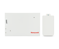
5800C2W / 5800C2WCN Convert to Wireless Module – Installation Instructions
GENERAL INFORMATION
The Honeywell 5800C2W Convert to Wireless Module (referred to as the 5800C2W, module, or 5800C2WCN in Canada) enables retrofitting existing security systems by; converting their wired sensors to Honeywell’s 5800 series wireless technology, and replacing the existing control panel with a LYNX Touch or LYNX Plus series control. The 5800C2W also works with residential VISTA control panels equipped with a wireless RF receiver and keypad. IMPORTANT: This product is NOT for use with fire / heat sensors. SPECIFICATIONS Dimensions Length 7.0 in (178mm) Width 4.5 in. (114mm) Depth 1.5 in. (38mm) Double stick tape and screws included. +14 to +140°F (– 10 to +60°C) 95% RH Max. Up to 300ft. (91 meters) Supplied by plug-in transformer 15.5VDC (± 5%) @ 1A P/N: 300-07052, or 300-07102 Canada Input Zones (9 hardwired) Auxiliary Output (12VAUX) LED Status Indicators Battery Backup Use 12V, 4Ah battery such as Honeywell 467, Yuasa NP4-12, Casil CA1240 or equivalent. Provides 4 hours of backup. Battery is to be located in the existing control panel. DO NOT use batteries of larger capacity. Activated when the cover is removed. • low battery • backup battery power • each enrolled zone transmits a supervisory message every 72 minutes • AC loss is reported as low battery (See LED descriptions on back page.) • input power • backup power • wireless transmission

Tamper Detection 5800C2W Supervision

Mounting Hardware Operating Temperature Humidity Transmission Range Operating Voltage

(The input power indicator is viewable through the enclosure cover.) All zones that are used must have an EOL resistor. (Refer to the back page for detailed information.) Provides 11.2VDC ±15% @ 100mA to supply PIR motion, or glassbreak sensors.

1

Mount and wire the module
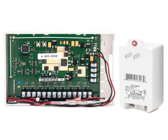
Mounting and Wiring: Note: This product must be installed in accordance with ANSI/NFPA 70, National Electrical Code. 1. Refer to the wiring diagram on the back. 2. Select a mounting position for the module. In most installations locating the module close to the existing control panel is ideal. Note: If needed, the 5800C2W can be located remotely by extending the existing sensor wires. If needed, you may cut and splice (observing good workmanship) the battery wires and extend their length up to 0.9 meters (3ft) using 22 AWG wire, minimum. Ensure the integral battery cable fuse is positioned inside the control panel enclosure. 3. Mount “Tamper Magnet” to enclosure cover. 4. Attach using the supplied double stick tape (and screws if desired). 5. Ensure the wiring is complete. Use cable ties as necessary to secure wiring. Plug the power transformer into an un-switched outlet and secure with screw. Then attach the backup battery wires.

Guidelines: • Since the existing control panel is being replaced, its security functions will be performed by the new LYNX or VISTA control panel. • The existing control panel can remain for the purpose of housing the backup battery. Further, the existing control panel can be powered down and the transformer unplugged. • The 5800C2W module will charge the battery. This is also a good time to replace the existing battery if needed. • At the existing control panel, tag and remove the sensor wires as they will now go to the 5800C2W. Up to nine [9] hardwired zones can be handled by each 5800C2W module. • DO NOT mount inside the control panel or other metal enclosure. • The integral battery cable fuse MUST be positioned inside the control panel enclosure. The fuse is not replaceable. • Before mounting permanently, conduct Go/No Go tests (see control’s instructions) to verify adequate signal strength, relocate if necessary.

2

Calibrate the module zones
3. DONE. The 5800C2W is calibrated and ready to enroll in the control panel. Note: If the 5800C2W loses both AC and battery backup power, the zone calibration data is retained.

Calibration: The calibration process enables the 5800C2W to learn what zones will be active and what value EOL resistors are used. Unused zones that are open WILL NOT be recognized and reported. 1. Ensure all zones are connected and not tripped. 2. On the 5800C2W, click the top left button (SW2). Indicator LED #1 will flash Red for 1/2 second, then turn steady Green.

3

Enroll the module in the control panel
Method 1: 1. Refer to the control panel’s guide and set it to “Zone Programming” mode. 2. Enroll the first zone as an "RF" type (supervised RF) device in the control panel.

Enrollment: As a wireless device, each 5800C2W has a unique 7-digit serial number to enable the control panel to recognize it. Further, since the 5800C2W has nine zones each zone is automatically assigned the next sequential serial number. Remember, unused zones are not reported or transmitted to the control panel. For example, below all zones except #6 are used: Item zone 1 zone 2 zone 3 zone 4 zone 5 Serial # xxx-xxx1 xxx-xxx2 xxx-xxx3 xxx-xxx4 xxx-xxx5 Item zone 6 (if not used) zone 7 zone 8 zone 9 Serial # none xxx-xxx7 xxx-xxx8 xxx-xxx9

3. Trip the zone (LED #1 flashes Green to indicate the information has been sent) and wait for the keypad to beep (about 2 seconds), then trip zone again. Confirm the correct serial number has been enrolled. Repeat for each zone used. Method 2: 1. Locate the unique 7-digit serial number for the 5800C2W module. This is located on the carton and on the module’s circuit board. 2. For each zone used, increment (in order) the 7-digit serial number to determine the serial number for each zone. Refer to the example table to the left. Note: The next step can also be done using Honeywell’s Compass software. 3. Refer to the control panel’s guide and manually program the 5800C2W module, followed by each of its zones. • All zones are Loop 1. • The 5800C2W tamper switch is assigned Loop 4 for the lowest numbered zone used.

• All zones are Loop 1. • The 5800C2W tamper switch is assigned as Loop 4 for the lowest numbered zone used. Enrolling the 5800C2W into the control panel is similar to any 5800 series wireless device. There are two methods that can be used.

LED #1 #2

Function Note: LEDs are shown as they appear on the circuit board. Red (blinking) – Module needs calibrating. Green – Module is calibrated. Green – DC power (15.5VDC, ± 5%) from the plug-in transformer is present. Red – DC power is NOT present. (Viewable through the enclosure cover.) Yellow – Low battery or No battery. When the battery voltage drops to 11.2VDC, a low battery message is sent to the control panel and LED 3 turns yellow. When the battery voltage drops to 10.0VDC, the battery is disconnected. The battery will not connect again until AC is restored. Green (blinking) – RF signal transmission.

#3

#4 Zone Calibration button. Not Used.

To backup battery located in existing control panel.

OBSERVE POLARITY.

Zone 1 of 9 shown wired.

Provides 11.2VDC ±15% @ 100mA to supply PIR motion, or glassbreak sensors. (Minimum voltage is 10.5VDC.)

NOTES: • All zones that are used MUST have an EOL resistor. • If the existing installation zones have EOL resistors (from 1k to 10k ohms) they may remain.

• For a NC loop without an EOL resistor, you must add one in series with the loop. • For a NO loop without an EOL resistor, you must add one in parallel (across) the
loop. Preferably it should be located at the end of the loop furthest away from the control panel.

• EOL resistor values must be from 1k to 10k
ohms. IMPORTANT: The first battery test occurs 1 hour after power up. To quickly verify a good backup battery, unplug and then plug back in the power supply; the system will perform a battery test within 1 minute.

FEDERAL COMMUNICATIONS COMMISSION STATEMENTS The user shall not make any changes or modifications to the equipment unless authorized by the Installation Instructions or User's Manual. Unauthorized changes or modifications could void the user's authority to operate the equipment. CLASS B DIGITAL DEVICE STATEMENT This equipment has been tested to FCC requirements and has been found acceptable for use. The FCC requires the following statement for your information: This equipment generates and uses radio frequency energy and if not installed and used properly, that is, in strict accordance with the manufacturer's instructions, may cause interference to radio and television reception. It has been type tested and found to comply with the limits for a Class B computing device in accordance with the specifications in Part 15 of FCC Rules, which are designed to provide reasonable protection against such interference in a residential installation. However, there is no guarantee that interference will not occur in a particular installation. If this equipment does cause interference to radio or television reception, which can be determined by turning the equipment off and on, the user is encouraged to try to correct the interference by one or more of the following measures: • • • • • • If using an indoor antenna, have a quality outdoor antenna installed. Reorient the receiving antenna until interference is reduced or eliminated. Move the radio or television receiver away from the receiver/control. Move the antenna leads away from any wire runs to the receiver/control. Plug the receiver/control into a different outlet so that it and the radio or television receiver are on different branch circuits. Consult the dealer or an experienced radio/TV technician for help.

INDUSTRY CANADA CLASS B STATEMENT This Class B digital apparatus complies with Canadian ICES-003. Cet appareil numérique de la classe B est conforme à la norme NMB-003 du Canada. FCC / IC STATEMENT This device complies with Part 15 of the FCC Rules, and RSS210 of Industry Canada. Operation is subject to the following two conditions: (1) This device may not cause harmful interference, and (2) This device must accept any interference received, including interference that may cause undesired operation. Cet appareil est conforme à la partie 15 des règles de la FCC & de RSS 210 des Industries Canada. Son fonctionnement est soumis aux conditions suivantes: (1) Cet appareil ne doit pas causer d’interférences nuisibles. (2) Cet appareil doit accepter toute interférence reçue y compris les interférences causant une réception indésirable.

WARRANTY Go to: http://www.security.honeywell.com/hsc/resources/wa/ DOCUMENTATION AND ONLINE SUPPORT Go to: http://www.security.honeywell.com/hsc/resources/MyWebTech/ 2 Corporate Center Drive, Suite 100 P.O. Box 9040, Melville, NY 11747 Copyright  2013 Honeywell International Inc. www.honeywell.com/security

Ê800-15422}Š
800-15422 9/13 Rev. B


Uploaded