Honeywell 5800WAVE Install Guide
Related Products
Related Categories
Document Transcript
K14400V1 8/08 Rev A
!"#$%& ()**+!,# !"#$%& ()**+!,# !"#$%& ()**+!,# !"#$%& ()**+!,#
+-./0/11 2-./3 $4560/ +-./0/11 2-./3 $4560/ +-./0/11 2-./3 $4560/ +-./0/11 2-./3 $4560/
!"#$%&&%$!'" %") #*$+, -+!)*
GENERAL INFORMATION
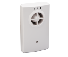
The 5800WAVE (Figure 1) is a wireless siren module that
contains an RF receiver and transmitter. The 5800WAVE
provides the following features:
• Compatible with the LYNXR Rev 10 or higher (with RF
enrollment) and LYNXR-EN self-contained controls or
with any other control that supports a 5883 Transceiver
Module.
• Transmits module status, including mounting tamper,
low battery, and AC loss to the control.
• Transmits supervisory check-in message.
• Provides temporal 3 pulse sounding during fire alarms
(which indicates evacuation of the premises).
• AC powered and mounts on any standard duplex
receptacle that is dedicated for use by this device.
• Contains a rechargeable battery that provides up to 12
hours of standby operation in the event of AC loss.
LED Activates Upon
Yellow Normally off. Blinks to indicate that an RF
message is being sent by the 5800WAVE. On
steady during RF Link test.
Green Normally on (lighted) when AC power is
present.
Red On when the system is armed. Off when the
system is disarmed. During RF Link test, on
indicates poor RF transmission.
INSTALLATION
The 5800WAVE must be powered overnight for the
battery to reach fuII capacity.
Connecting the Battery and Setting the House ID
When separating the case front from the back use
care not to damage the wire Ieads connected to the
sounder and circuit board. Refer to Figure 2.
1. Remove the four screws located in the back of the unit.
2. Separate the case front from the back.
3. Check that the standby battery is held securely in place
by the two battery clips as shown in Figure 2.
4. Plug the standby battery connector into the PCB
connector as shown in Figure 2.
5. Set DIP switches 4-8 to the appropriate House ID (1-31)
See Figure 3. The House ID set by the DIP switches
should match that entered in the control.
6. Close the 5800WAVE’s case and reinstall the four screws
removed in step 1.
Verifying the RF Link
Dip switch 6 on the 5883 must be set to ON to enabIe
its RF transmitter.
The security system controI must have the House ID
set and must not be in the Test Mode or
Programming Mode when checking the RF Link.
1. Plug the 5800WAVE into the AC receptacle at the
desired location. The green LED will light indicating AC
is present and the 5800WAVE is powered. The yellow
LED will light for approximately 15 seconds.
• If the red LED turns on, the RF link is bad. Relocate
the 5800WAVE to another AC receptacle (closer to
the control) and repeat step 1 to verify the RF Link.
• If the red LED remains off, the RF link is good and
you may complete the installation at this location.
2. Unplug the 5800WAVE and proceed to “Enabling
Module Supervision”.
EnabIing ModuIe Supervision
The 5800WAVE is supervised by the control for loss of RF
check-in transmissions, low battery, loss of AC, and
mounting tamper.
The 5800WAVE reports AC loss and low battery as Low
Battery to the control (and will not cause an alarm when the
control is armed).
If an AC Ioss condition exists "Low Battery" is
dispIayed on the controI keypad (with the
programmed zone number) and the Green LED on
the 5800WAVE is off.
Program the 5800WAVE in the control as a zone and enroll
its serial number as described using the installation and
setup guide supplied with the control and the information
below.
Note the following when enrolling:
Zone type = 5 (trouble by day / alarm by night)
Input type = 3 (Supervised RF)…..Loop number = 1
1. When prompted for the serial number, you can either
enter it manually or transmit from the device.
a. To enter the serial number manually, read the
number from the label on the device and enter it via
the control’s keypad (referring to the zone
programming section of the Installation and Setup
Guide for the control).
b. To transmit the serial number, plug the 5800WAVE
into an AC receptacle. Within 15 seconds, place the
tamper magnet next to the tamper position-indicator
lines on the case (Figure 4) and wait until the yellow
LED turns off, and then remove the magnet to cause
a transmission.
The yellow LED will flash when the transmission is sent.
2. When the enrollment is complete, exit programming
mode and unplug the 5800WAVE. Proceed to step 3 if
mounting tamper is desired. Otherwise proceed to
“Completing Installation”.
3. Mount the magnet (using the screws supplied) to the
wall, adjacent to the case, between the tamper position
indicator lines as shown in Figure 4.
Verifying Tamper Operation (if used)
1. Plug the 5800WAVE into the AC receptacle. Wait until
the yellow LED turns off and clear any tamper fault
caused by the 5800WAVE from the control.
2. Unplug the 5800WAVE from the AC receptacle and
verify that the control now indicates the tamper fault.
CompIeting InstaIIation
1. Remove the screw that secures the cover plate to the
duplex receptacle. Leave the cover plate in place on the
receptacle as shown in Figure 5.
- 2 -
2. Plug the 5800WAVE back into the AC receptacle.
3. Insert the hold down screw (supplied) in the 5800WAVE
mounting hole and secure the case to the receptacle as
shown in Figure 5.
4. When the yellow LED turns off, arm the control and
verify that the red LED turns on. Then disarm the
control.
5. With the control in the TEST Mode, test the 5800WAVE
sounder by causing an alarm.
5
8
0
0
W
A
V
E
-0
0
1
-V
0
RED
LED
YELLOW
LED
GREEN
LED
SIREN
OUTLET
INDEXER
MOUNTING
HOLE
2
3
4
5
6
1
7
8
ON OFF
5
8
0
0
W
A
V
E
-0
0
4
-V
1
SIREN WIRE
HOLD DOWNS
BATTERY
JUMPER
(DO NOT REMOVE)
BATTERY
CONNECTOR
BATTERY
CLIPS
TERMINAL BLOCK
(NOT USED)
+
+
./0123 45 67889%:* #/23; <=>1?3 ./0123 @5 ABCC32D B;> #/23; E=;;3FC/=; ,=/;CG
DIP SWITCH POSITIONS DIP SWITCH POSITIONS House
ID 4 5 6 7 8
House
ID 4 5 6 7 8
0 – – – – – 16 ON – – – –
1 – – – – ON 17 ON – – – ON
2 – – – ON – 18 ON – – ON –
3 – – – ON ON 19 ON – – ON ON
4 – – ON – – 20 ON – ON – –
5 – – ON – ON 21 ON – ON – ON
6 – – ON ON – 22 ON – ON ON –
7 – – ON ON ON 23 ON – ON ON ON
8 – ON – – – 24 ON ON – – –
9 – ON – – ON 25 ON ON – – ON
10 – ON – ON – 26 ON ON – ON –
11 – ON – ON ON 27 ON ON – ON ON
12 – ON ON – – 28 ON ON ON – –
13 – ON ON – ON 29 ON ON ON – ON
14 – ON ON ON – 30 ON ON ON ON –
15 – ON ON ON ON 31 ON ON ON ON ON
“–“ Indicates “OFF.”
2
3
4
5
6
1
7
8
O
N
O
F
F
5
8
0
0
W
A
V
E
-0
0
5
-V
0
SWITCHES 1,2,3
MUST BE SET TO OFF
HOUSE ID 16 SHOWN
5
8
0
0
W
A
V
E
-0
0
3
-V
0
TAMPER
POSITION
INDICATOR
LINES
./0123 H5 )!, #I/CFJ #3CC/;0G
./0123 K5 'LC/=;B? $BML32
- Uploaded