Honeywell Home Tuxedo Touch WIFI - Install Guide - Dated 08/15 Rev. C
Related Products
Related Categories
Document Transcript
Tuxedo Touch
™ Wi
-Fi®
Mod
els T
UXWIFIS and TU
XWIFIW
Home A
utomation System
Installation and Setup
Guide
800-16571V2C
8/15 Rev
. C
TUXW
IFIS/TUXWIFIW
Z
-
Wave devices are
i
dentified by
the Z
-
Wave logo and can
be purchased from
your local retailer.
Z-Wave
®
is a registered trademark Sigma Designs, Inc. and/or its
subsidiaries.
i
Table of
Contents
ABOUT THE SYSTE
M ......................................
1
Tuxedo Features
...................................................
1
Control Panel Compatibility
................................
.........
2
Front Panel LED’s
................................
......................
3
MOUNTING
.......................................................
3
Standard Mounting with Mounting Plate
......................
3
Mounting Without Mounting Plate
...............................
3
Mounting Using a Center Securing Screw
...................
4
Wiring
....................................................................
4
ECP
Wire Limita
tions
................................
..................
4
Supplementary Power Supply Connections
................
5
PROGRAMMING THE CONT
ROL PANEL
......
5
Conventional Programming Methods
....................
5
Residential Control Panels
..........................................
5
Commercial Control Panels (Non-
Turbo)
....................
6
Vista
-Turbo Commerci
al Control Panels
.....................
6
Quick Programming (VIP Mode)
............................
6
Data
Entry Keybo
ard
.............................................
6
FIRST TIME SETUP
..........................................
7
First Time Power Up (Keypad Initialization)
...........
7
1: Operational Mode Setup
................................
.........
7
2: Set ECP Address/RIS Automatio
n Address
............
8
3:
Resideo
End User License Agreement (EULA)
.......
10
4: Network (LAN/Wi
-Fi) Setup
.....................................
10
5: Important Operation Information
.............................
10
6: Remote Login
.........................................................
10
7: Voice Disclaimer
.....................................................
10
8: Voice Tutorial and Setup
................................
.........
11
HOME PAG
E ...................................................
12
SETUP SCREEN
.............................................
13
System Information
................................................
13
Software Upgrades
.....................................................
13
Display & Audio Setup
................................................
14
Language Selection (if applicable)
..............................
14
Screen Time O
uts
................................
.......................
14
Temperature Unit
........................................................
15
Clean Screen
..............................................................
15
IP
(Setup)
..............................................................
15
Wi
-Fi Setup
.................................................................
15
Manual Network Setup
...............................................
15
Static Network
............................................................
15
Port Settings
................................
...............................
15
Webserver Access
................................
......................
16
Local Access
..............................................................
16
Web Serv
er IP Address Access
................................
.. 17
Connecting the Tuxedo to a mobile device
.................
17
Local Web Server URL Access
................................
... 18
Remote Access Using Port Forwarding
......................
18
Email Setup
...........................................................
18
User Email
Setup
........................................................
19
Defining Event Types
................................
..................
20
SYSTEM SETUP
.............................................
21
Quick Programming
...............................................
21
Quick Programming Menu’s
................................
.......
21
CS S
etup (Central Station)
....................................
22
ECP Addres
s .............................................................
22
Options
................................
......................................
22
Code Authority
................................
...........................
22
Device Events
............................................................
22
Time/Date Setup
....................................................
22
User Codes
............................................................
23
Authority Levels
.........................................................
23
Add a User
................................
.................................
23
LCD Display Test
................................
.......................
24
Audio Test
.............................................................
24
LED Test
....................................................................
24
Calibration
................................
.................................
25
Z-Wave Test
..............................................................
25
Keypad Reset
............................................................
26
End User License Agreement (EULA)
........................
26
Factory Default
..........................................................
26
Output Setup
..............................................................
26
Night Setup Function
.................................................
26
Power Mode Setup
....................................................
27
Multimedia
.............................................................
27
Picture & Slide Show Setup
.......................................
27
Camera Options and Setup
...................................
28
First Time Setup
.........................................................
28
Add/Edit Options
................................
........................
29
Setting the Camera’s Wi
-Fi ................................
........
29
Advanced Camera Settings
................................
........
30
Removing Cameras
................................
...................
31
Viewing Cameras
...................................................
31
Video Recording & Event Viewing
.........................
31
Manual Video Recording
............................................
32
Using Third Party Cameras
................................
........
32
Event Viewing
............................................................
32
Video Playback
..........................................................
33
Creating Scenes for Camera Recording
.....................
33
Message
(Voice Memo’
s) ......................................
33
Recording a Message
................................................
34
Listening to a New Message
......................................
34
Deleting Me
ssage(s)
................................
..................
34
Z-WAVE SETUP
..............................................
35
Z-Wave device Management Screen Device List
.. 35
Z-Wave Device Management Buttons Defined
......
36
Adding and Deleting Z
-Wave Devices
...................
36
Z-Wave D
evice Setup
............................................
38
Changing the Name
................................
...................
38
Changing the Icon
......................................................
38
Association Details
.....................................................
39
Z-Wave Network Update
.......................................
39
Individual Device Update
...........................................
39
Complete Network Update
................................
.........
39
Creating Scenes
....................................................
40
Defining Scenes
.........................................................
41
Scene
Setup Options
.............................................
43
Detailed Scene Configuration
.....................................
45
Room Setup
...........................................................
46
Secondary Tuxedo Controller
.....................................
46
Synchronizing Device Names
................................
....
47
Removing Secondary Tuxedo’s
..................................
47
Manual Z
-Wave De
vice Control
..................................
47
ii
INTEGRATING TOTAL CO
NNECT REMOTE
SERVICES
.......................................................
48
Enabling Devices for Total Connect
......................
48
Controlling Automation (Z
-Wave) Devices Remotely
48
VIEWING
AND CONTROLLING TOTAL CONNECT
SCENES FROM TUXEDO
..............................
49
Creating Scenes in Total Connect
.........................
49
Total Connect Server Screen for Troubleshooting
.......
49
APPENDIX A:
IMPORTANT
NOTES
..............
50
General Notes
.......................................................
50
Commercial System Notes
....................................
50
Residential System Notes
......................................
50
User Related Notes
...............................................
50
APPENDIX B: Z
-WAVE N
OTES
.....................
51
Z-Wave Compatible Devi
ces
.................................
51
APPENDIX C:
WIRELESS RANGE
................
52
Things to consider regarding RF range:
.....................
52
Con
trolling Device
s: ...............................................
52
Effects of Home Construction on Wireless Range between
Z-Wave Enabled Devices
......................................
52
NAVIGATION ICONS
......................................
53
SPECIFICATIONS
...........................................
54
NOTE:
This
device
is a Security Enabled Z
-Wave Controller
TUXEDO TOUCH WI
-FI INSTALLATION & SETUP GUIDE
1
About
the
System
Th
is guide provides i
nformation
to install
an
d set
-up
Res
ideo
’s Tuxedo Touch™ Wi
-Fi
®
Home
Automation
and Security
System
(herein referred
to as Tuxedo).
Tuxedo is an
Advanced User Interface (AUI) device, which comb
ines wireless
home automation and
security.
Tuxedo connects t
o a VISTA
®
series contro
l panel via the
keypad
(ECP) terminals
, or
used as a
stand
-alone
unit for automation purposes
.
Tuxedo Features
Feature
Description
Local Wi
-
Fi
Access
The Tuxedo keypad c
ontains a built
-
in web
server, which
allows local Wi
-
Fi access
to the system
via any w
eb-enabled
device.
In addition, a user account can be set up
, which provides a user name
and
password login before entering the Tuxedo home screen to protect against unauthorized
access.
Resideo
Total Connect
™
Remote Services
Tux
e
do
supports Remote Serv
ices for con
trolling Z
-
Wave devices and sc
enes remotely from an
associated Total Connect™ account (contact an AlarmNet
® representative to open an account if
necessary).
With Tuxedo automation, Z-
Wave devices can be controlled from a
smart phone, i
Pad
®, And
roid
TM
Table
t, or PC using Tot
al Connect.
Tuxedo includes webpage support for
IE9.
Remote
Ac
cess
(Port
Forwarding)
Tuxedo’s r
emote access
option
allows the user to acc
ess Tuxedo’s menus directly via the Internet
when away from home
. Port forwarding set i
n the router
is required
. Up to five user logins
available
. Refer to the router’s instructio
ns for details on port forwarding.
See
“Support
ed
Browsers Section.”
Z
-
Wave Devices
Tuxedo suppo
r
ts various Z
-
Wave devic
es, includin
g lamp modules, dimmer modules, door locks,
thermostats
, water valves, garage door
controllers
and shade openers.
Automation
Scenes
Define system actions
f
or automatic start and stop parameters
when certain co
nditions o
c
cur.
Supports up to 3
0 scenes
loca
lly and 20
remotely
through Total Connect
.
Cameras
View up to four cameras at the
same time
with a maxim
um enrollment of
32 came
ras.
Video
View videos fro
m the Home screen
.
A video converter is required
, requires MP4
f
ormat for
playback
.
Se
e Video Setu
p section for details.
Security System
Control the security system via Tuxedo men
us.
Offers burglary protection and may prov
ide fire,
carbon monoxide and
emergency protection.
Email Notification
Receive email notifica
t
ions when certain event
s occur.
No
tifications
are
to up
four email
addresses.
Weather Forecast
The *Weather forecas
t (if enabled) is displayed on
the “Home” screen.
Press the “Weather” fea
ture
to enter your location and temperature unit.
Output Setup
F
unction
Tuxedo can acti
vate/deactiv
ate up to
18 pre
-
defined
panel output
s
(if programmed in the control
panel).
Thes
e output functions are typically used to turn on lights or activ
ate relay
devices.
Safe Mode
In the rare event that the keypad cannot suc
c
essfully communicate in
its
graphic
mode with the
control panel, the Safe Mode is a backup mode that ensures that you
can communicate with the
system.
In this mode, the keypad operates much like a standard non
-graphic keypad so that you
can control the s
ystem until the problem is c
orrected
.
IMPORTANT
DO NOT perform panel programming while in the Safe Mode.
Performing p
anel programming
while in Safe Mode may cause the panel and keypad to become out of synchronization.
DO NOT use several hardwired motion d
etectors in high traffic
locations.
The high quantity of
signals received by the panel may cause the keypad to enter
the Safe Mode.
The actual number of
installed detectors depends on the am
ount of traffic and the number of detectors being used.
High
tr
a
ffic can cause S
afe Mod
e with as fe
w as three detectors.
Blank Display
The Blank Display (EN50131) feature prevents
unauthorized users from viewing the status of the
Security System by retur
ning to the Home screen and turning off the Armed and Ready stat
us LEDs.
When th
e EN501
31 Display i
s turned ON:
Tuxedo returns to the "Home" screen after 30 seconds
and
“Armed" and "Ready" LEDs turn OFF.
The "To Homepage After" time setting changes to 30
seconds and the time is non
-selectable.
The “Auto Slideshow Af
ter” is preset to “1” mi
nute and cannot be changed.
The Security, Message and Lighting screen does not display system status until an authorized
user code is entered.
The "Setup" menu does not
display system status until an authorized user code is entered.
Videos can
not be played
.
Night Set
up
Pressing
NIGHT
icon
the system in the
STAY INSTANT
mode by default.
This funct
ion can be
changed to arm in one of several other modes if desired.
Refer
to the “Night Setup” section for
details.
TUXED
O TOUCH WI
-FI INSTALLAT
ION & SETUP GUIDE
2
Feature
Description
Switchable
Themes
Sw
i
t
ch from normal view to
mobile view
depending on the type of device used with the Tuxedo.
Refer to Remote Access section for details.
Software
Upgrades
Software upgrades may be available fo
r this product.
To ensure you have the latest version, check
the version in your system
(see the Software Upgrades section for details).
U
L
Web s
erver hosting
,
Remote Arming/Di
sarming/Programming
, Wi
-
Fi, and Email Notifications are supplementary only
and
not
listed
for use in
UL
compliant
installations.
Control
Panel
Compatibility
The
table below
list
s compatible control panels and
their software revision levels.
NOTE
:
For SI
A installations used with a VISTA
-128BPTSIA Control, see the SIA CP
-01 Qui
ck Reference Chart
by visiting
:
www.resideo.com
Maximum
Number
of
Keypads
Mi
nimum
Soft
ware
Revisi
on Level
Voice Chime
Alarm System
VISTA
-
15P, VISTA
-
20P, FA148CP,
FA168CPS
2
3.0
Yes
V
ISTA
-
20P, FA168CPS
4
5.0
Yes
*
VISTA
-
21IP
4
1.0
Yes
V
ISTA
-
128BP, V
ISTA
-
250BP
3
4.4
No
V
ISTA
-
128BPEN
3
7.0
No
V
ISTA
-
128FBP, V
I
S
TA
-
250FBP,
FA
1670C
3
4.1
No
V
ISTA
-
128FBPN
3
5.1
No
V
ISTA
-
128BPT, V
ISTA
-
250BPT,
V
ISTA
-
128BPTSIA, FA1660CT
6
10.1
Yes
FA1660
C, FA1700C
3
3.0
No
**
Vista
-
128FBPT, Vista
-
250FBPT,
Vista
-
32FBPT
6
10.0
Yes
* Not evaluated by UL.
** Not for UL 864 Commercial Fire Alarm A
pplications
NOTE:
Tuxed
o may only be used in the following UL/cUL installations: UL 365, UL609,
UL 985, U
L1023, U
L 1610, CAN/ULC
-S303, CAN/ULC
-S304, ULC
-S545, ULC/ORD
-
C1023, and ANSI/SIA CP
-
01
-
2010.
To obtain the
s
oftware revision level
on commercia
l panels:
•
From
program mode
, enter
#92
on the keypad
(this can be done from the Console Mo
de)
.
The
second line of the keypad displays t
he software revision level (w/
out the decimal point).
To obtain the software revisio
n level on residential panels:
•
From
the Home Screen p
ress
Setup
>
System Setup
>
Central Station
Setup
>
enter
install
er code
>
Panel
Configuration
; the software revision level is displayed.
•
The keypad sound suppression feature
is available in some comme
rcial panels
and
is not
compat
ible
with the Tuxedo
keypad
.
•
The ‘Voice Chime’ feature is a residential control feature
only
(r
efer to the table above).
NOTE
:
If using the maximum number of k
eypads, an additional auxiliary
power supply may be needed.
Ref
er to the
“Wiring”
and “
Spe
cificatio
ns”
section for more information.
TUXEDO TOUCH WI
-FI INSTALLATION & SETUP GUIDE
3
Front Panel LED’s
The Tuxedo keypad has three L
EDs as f
ollows:
FLASHING –
The system contains new
message(s) for the Use
r.
OFF – No new messages.
RESE
T BUT
TON
Press to reset keypad
ON – System is armed.
OFF – System is not armed.
ARMED (RED) LED
READ
Y (GREEN) LED
ON – System is disarmed and ready to arm.
OFF – System is armed or disarmed but not
read
y. If disarmed, faults or troubles are prese
MESSAGE (YELLOW) LED
SD/SDHC CARD Slot
Mounting
Tuxedo is for indoor use within the protected area only and mounted at a comfortable viewing level.
Avoid
mounting
in
areas of hi
gh condensatio
n such as bathrooms or in locations where bright light or sunlight shines directly
on the
screen.
Tuxedo can be mounted with or without the mounting plate.
Use the center securing screw for European
installations.
Standard Mounting with Mounting Plate
1.
Select a mounting location.
2.
Detach the mounting plate by sliding downward.
3.
Use
the moun
ting plate to mark the location of the
mounting holes on the mounting surface and check
for level.
4.
Locate the mounting plate ove
r the mounting
surface s
uch that the
wire/cable access openings
are aligned while passing the wires/cable through
the
case bac
k.
**
Go to
Wiring
and complete wiring.
5.
Secure the mounting plate to mounting surface
using
four
screws (supplied).
6.
Slide keypa
d onto mounting plate.
Mounting Without Mounting Plate
1.
Select a mounting location.
2.
Detach the mounting plate by slid
ing down
ward
and discard.
3.
Use the template (provided in the carton) to mark
the location of the mounting screws and the cut
-
out for the ke
ypad assembly on the mou
nting
locati
on.
Check for level.
4.
Install
four
screws (supplied)
in the mounting
surface leav
ing scre
w heads 1/8” above the
mounting surface.
5.
Locate the case back over the mounting surface
such that the opening is aligned with the
wire/cable access openi
ng on the mo
unting surface
while passing the wires/cable through the opening
in the case back.
**Go
to “
Wiring
” and complete
wiring.
6. Mount keypad by sliding onto the screw heads.
6280-016-V1
MOUNTING
SCREWS
INS
TALLED
1/8”
ABOVE
SURF
ACE
TEMPL
ATE TUXED
O TOUCH WI
-FI INSTALLAT
ION & SETUP GUIDE
4
Mounting Using a Center Securing Screw
NOTE
: Applies to European In
stallations.
1.
Detach case front by removing the two
bottom screws
. Gently pull up using a
screwdri
ver if necessary and pry apart.
Lift off cover.
2. Mount Tuxedo in its final location, (see
“Standard Mounting” or “Mount
ing
wit
hout the mounting plate”
) install
center securing screw (supplied) and
tighten to mounting surface.
3. Replace the case front
and secure
using the two bottom screws.
The European mounting procedure has not been evalu
ated fo
r agency compliant appli
cation.
Wir
ing
Connect the Tuxedo in parallel with keypads and other peripheral devices usin
g the ke
ypad data (ECP) bus, by adher
ing to
the standards below.
ECP Wire Limitations
Connect keypads and other addressable devices as show
n in
“Supplementary Power Supply Connections”
section.
The
table bel
ow establishes ECP device wire gauge
:
Wire
Gauge
Length
#22 gauge
150 feet
#20 gauge
240 feet
#18 gauge
350 feet
#16 gauge
550 feet
Tuxedo draws up to 340mA for 9.6VDC, 260mA for 12VDC, 250mA
for 13.8VDC
. If you power Tux
edo from
your panel’s Aux Power
output, check your panel’s Installation and Setup Guide and verify
that this device and others do not exce
ed your panel's Aux Power
output capability. If it does, a supplementary power supply is
needed.
•
If more than one T
uxedo is
wired to one run, then the
maximum lengths must be divided by the number of
keypads on the run.
(e.g., the maximum length is 75 feet if two Tuxedos are wi
red on a #
22-gauge
run).
•
If Tuxedo is used as the primary system keypad, maximum wire run le
ngths mu
st not exceed the lengths
listed in the table above.
6280-015-V1
INSTALL CENTER
SECURING SCREW
DETACH CASE FRONT
BY REMOVING SCREWS (2)
AND LIFT UP
CASE
FRONT
CASE
BACK TUXEDO TOUCH WI
-FI INSTALLATION & SETUP GUIDE
5
Supplementary Power Supply Connections
IMPORTANT NOTES:
•
If an auxiliar
y power supply is used, yo
u MUST con
nect a common ground as shown above.
•
When Tuxedo is powered from an auxiliary powe
r supply
, always apply power to the control panel first and
then to Tuxedo.
Failure to observe this sequence results in improper operation
of the keypad and may re
sult
in a
n ECP Error indication.
•
Supplementary external power supply must be listed to UL603
for UL Burglary Installations and UL1481
for UL Residential Fire Installations.
Programming the Control Panel
Conventional Programming
Methods
The keypad is n
ot fully ope
rational unless its address in the control panel ha
s been enabled (set as an alpha
console
) AUI type device, and assigned to a partition (where applicable).
For a list of compatible alarm systems,
refer to the Control P
anel Comp
atibility
for t
he
quantity
of keypads that may be used with the Tuxedo and the
required control panel
’s softw
are revi
sion level.
We recommend that you use either a standard alpha keypad or the keypad in Console Emulation Mode when
programming the c
ontrol p
anel.
When in th
e Console Mode, the keypad emulates an alpha keypad and the
programming of the panel is perf
ormed following the procedures provided in your panel’s Installation and Setup
Guide.
NOTE
:
When programming your control panel, if you ch
ange t
he zone types for
your emerge
ncy zones you may disable the
emergency
icons
in the keypad.
The emergency
icons
in the k
eypad are active for zone types 06 (Silent Panic
Button), and 07 (Panic Button), 08 (Medical Button), and 09 (Fire Button).
Addit
ionally, the Medical but
ton is also
compatible with a zone type 15 (24-
Hour Medical) for panels that contain this zone
type.
Review the table under
the section
Control Pane
l Compatibility
for the total numbe
r of keypads compatible an
d the revi
sions required.
Residential Control Panels
Residential Control Panels consist of t
he VISTA
-20P, VISTA
-21IP and VISTA
-15P and equivalents.
•
Addresses
one
and
two
(in field *189) are enabled by default.
If the defaults
ha
ve been changed, enable
these
addres
ses (in field *189) using an alpha-keypad and the Data Field Programming procedure
s locate
d in the
panel Installation and Setup Guide.
•
If using Resideo
Total Connect™ Remote Servi
ces, here in referred to Total Connect):
o
Resideo
residential cont
rol panel re
vision 9.18 (3.13 for the Vista-
21IP) and under must program the
Remote Interactiv
e Se
rvice option in the second location in *91 to a 2 (by default location 1 is set to 8, so th
e
entry would be *91=82)
o
Resideo
residentia
l control panel revision
10.0 (4.21
for the Vista
-21IP) and higher supports the RIS option
by default, hence there is
no
programming location to enable.
Common Ground
TUXED
O TOUCH WI
-FI INSTALLAT
ION & SETUP GUIDE
6
Commercial Control Panels (Non-
Turbo)
Commercial Control
Panels consist of the VISTA
-128BP, VISTA-250B
P and
VISTA
-128FBP, VIST
A-250FBP and
32FBP
or equivalent.
•
Addresses 1-2, and 3-30 may be used for older controls under
revision 10, which supports three
AUI’s. These
addresses in the control panel are not def
aulted for AUI type devices.
To enable the add
resses you are using for
keypads, us
e an alpha
-keypad and follow the procedures for “Device Programming” in your control
panel
“Programming Guide.”
NOTE
:
It is recommended that address 1 is programmed for AUI
and one of the
keypad is assigned to it
.
•
If mu
ltiple keypads are being
used, they must be set to addresses 1, 2, and X (where X equals any address from
three
throug
h 30).
Only one AUI type device may be assigned to an address from three
through 30 on
com
mercial control panels under revision 10.
Vista
-Turbo
Commercial Control
Panels
Th
e commercial family consist of the VISTA-128BPT, VISAT
-250BPT
and VISTA
-128FBT, VI
ST
A-250FBPT
, 32FBPT or
equivalent.
•
Any address 1-
30 can be used for an AUI keypad, the Vista-Turbo panels can support up to 6 AUI keypads
•
If using Total Connect the
RIS optio
n must be enabled in the panel. This is enabled by setting the device type
to 12 fo
r the address. Refer
to the AlarmNet Communicator to determine which address to use (See “Important
Notes” below.)
Important Notes:
•
Th
e RIS option
must
be ena
bled in the
AlarmNet Communicator. Failure to do so will prevent control of the
automation de
vices enrolled in the keypad from Total Connect.
•
The Keypad should not be assigned as a Master Console.
If the keypad is assigned as a Mas
ter Console
(partition
9), partitio
ns must be controlled from the Partition screen or using the Console Emulation Mod
e.
Quick Programming (
VIP Mode)
Tuxedo supports Quick Programming VIP (Vista
®
Intelligent Programming) mode when used with a control panel
that supports this feat
ur e. Check
the control
panels
manual to check if it supports this function and for further
instructions.
See the
“Quick Programming”
section for more
information
.
Data Entry Keyboard
Thro
ughout this document, th
e user is re
quired to enter information on the Tuxedo Keypad (i.e., password, device
names etc
.) Use the Data Entry K
eyboard to enter all required information
.
•
Press the
U
p Arrow
to switch to upper case characters.
•
Press the
Space
key
to add a space betw
een characte
rs.
•
Press the
X
key to delete/backspace.
•
Press the
ABC/123
key to switch between
nu
merals and symbols/characters.
•
Press
GO
to return to the previous screen.
TUXEDO TOUCH WI
-FI INSTALLATION & SETUP GUIDE
7
First Time Setup
First Time Pow
er Up (Keypad Initializ
ation)
After
first time power up
(or
a keypad
default)
, the
Tuxedo steps through the following
setup prompts.
1.
Operational Mode Setup
2.
“ECP” and “RIS” address selections
3.
Resideo
Privacy Statement and End
-User License
Agreement
4.
Wireles
s Local Area Network (
WL
AN/
LAN)
conf
iguration
5.
User Setup “Important Operation
Information”
6.
Remote Login Setup
7.
Voice: D
isclaimer/Limitation of Liability,
followed by a t
utorial video
8.
Voice Tutorial
Introduction
These options can also be set later using the
appropriate menus.
Inst
aller Note:
The Tuxedo touch
-screen has been calibrated at the factory.
Ignore the “CALIBRATE”
icon
that appears
on the “Options” screen after initial ECP setup
. If the screen should require recalibration, the end user may do so v
ia
the “Keypad Test” scr
een. See th
e
“Diagnostic Tests”
section.
1:
Operational Mode Setup
Languages
The option for English is defaulted and non
-selectable. This is there for future updates.
Blank Display
The “Blank Display” option is enabled by selecti
ng the
checkbox next to
“EN50131.”
For a list of functions and
features of
“EN50131,”
refer to the
“About the System
”
section.
Operating Modes
Normal Mode
Normal Mode is used for Resideo
security control inte
gration
.
Safe Mode
The Safe Mode may be automatically entered by the program on a communication failure or may be entered man
ua
lly
on command.
To Enter Safe Mo
de:
1. Select
Safe Mode
>
Apply
>
OK
.
2. To exit, press
safe mode bar
press
YES
to return to Normal Mod
e.
•
While in the Safe Mod
e, the Home
screen displays the Security, Panic, and Message Icon.
A messa
ge
!SAFE
MODE!
Is displayed at the lower left side of the screen.
•
Tuxedo resets and restarts in the Safe Mode.
In the rare event that Tuxedo cannot successf
ully communicate in its graphic mode
with the control panel, the Safe
Mode is a backup mode that
ensures that you ca
n communicate with your system.
In this mode, Tuxedo operates much like a standard non
-graphic keypad so that you can control your system u
ntil the
problem is correc
ted.
If t
his situation occurs, Tuxedo presents you with a message of
“Problems detected.
Start Keypad in Safe Mode?”
and requests a
YES
or
YES
response.
If you answer with
Yes
,
Tuxedo enters into the Safe Mode.
If you answer w
ith
NO
,
Tuxedo tries to
communicate
with the panel again.
After
three
consec
utive times of receiving no response, Tu
xedo
enters the Safe Mode automatically.
NOTE
:
Use care when providing the “Yes” or “No” response.
Pressing the screen outside the prescri
bed area may
cause the background t
o come to the front.
If this occurs, th
e Yes/No message that disappeared times-
ou
t in 30
seconds even though it is not visible.
Then Tuxedo resets into the Normal Mode (or Safe Mode if this is the third time
that the w
arning message appeared)
.
Note that this is a limited mode of operation.
While in this mode:
•
You can use
Security
to access the Console Emulation Mode of operation to try to clear your faults, disarm the
system, or enter additional Alpha Keypad commands sp
ecified in your panel U
ser Guide.
You can perform
almost all functions that you can perform from a standard non
-grap
hic alpha keypad.
•
You can press the “Panic” key and generate Emergency Messages as defined in the panel’s home partition for
this keypad.
•
The Armed and Ready LED
s on the fro
nt of the keypad indicate
s Tuxedo’s home partition status.
The Message
LED (on
mo
dels with Voice feature) or Trouble LED (on models without Voice feature) is not active in the Safe
Mode.
TUXED
O TOUCH WI
-FI INSTALLAT
ION & SETUP GUIDE
8
•
The Chime mode functions in the S
afe Mode, however, you do
not have
Voice (system status me
ssages), Voice
Chime (announcements) or Message capabilit
y (if set to default “Master”).
•
Z
-Wave Scenes do not function in Safe Mode.
•
When an alarm occurs in the Safe Mode, it is displayed on the
Console mode screen onl
y and is not
shown on the
Home sc
reen.
•
The Slide Show feature does not start automatically in
Safe Mode.
To Exit the Safe Mode:
1.
Press the
! SAFE MODE !
bar
.
2.
Press
YES
to return to Normal Mode.
Tuxedo
Wi
-Fi
resets and normal op
eration returns as
long
as
the origi
nal
conditions that caused the entry into Safe Mode do not still exist.
Demo Mod
e
Demo Mode allows the automation and multi
-media features to operate in a non
-security mode for demonstration
purposes only.
Automation (Oc
cupancy) Mode
This mode
is primarily
used with the Scenes features to automate certain scene actions and does not co
mmunicate
with the control panel.
NOTE
:
The Automation/Demo Mode option allows the automation and multi
-media features to operate
in a non
-
security mode.
When this
option is s
elected, the keypad does not communicate with the control panel and any user
can
select Advanced Setup screens.
Automation mode allows you to set Tuxedo in two conditions: Residential and Commercial.
Scenes can be set t
o
trigger bas
ed on the
status of th
ese settings
:
•
In
Residential
mode (default), the Arming options are
Home
,
Away
, an
d
Night
.
•
In
Commercial
mode, the Arming options are
Open
,
Close
, and
Night
.
Residential Mode
From the “Hom
e”
screen,
press
Setup
>
System Setup
>
CS Setup
> Enter
your authorized >
Options
; the “OPTIONS and OPERATING MODES” screen is display
ed. Highlight the
Automation Mode
check
box to enable the
option.
To change the occupancy delay time, (the amount of time you want to allow
for authorized entry or
exit withou
t
causing an alarm) select a time interval from the
Occupancy
Delay
drop
-down li
st: choose from
15, 30, 60, 120
or
225
seconds.
When done
, press
Apply
to save the settings
.
The message is displayed
“
WARNING Keypad
will reset to activate ch
an
ges ... Do y
ou want to save changes.”
Select
Yes
or
No
.
Commercial Mode
To enter Com
me
rcial mode (automation), from the “Home” screen press following
:
Setup
>
System Setup
>
CS
Setup
. Enter your authorized code and p
ress
Options
; the “
Opti
on
s and Oper
ating Modes
” s
creen is displayed.
Highlight the
Automation
Mode
check box to en
able th
e option then select the
Commercial
check box.
To change the occupancy delay time, select a time interval from the
Occupancy
Delay
drop-down list: choose fr
om
15,
30, 60, 120
or
225
seconds.
When done, press
Apply
to save the settings
.
The me
ssage
display
s
“WARNING Keypad will reset to activate changes ... Do
you want to save changes.”
Select
Yes
or
No
.
2: Set ECP Address/R
IS Automation Address
Re
view the pan
els programming for the prope
r keypad AUI address
.
•
If the system is using only
one
properly programmed Tuxedo
(in the control panel)
, leave the address set to one
and
press
APPLY
, for more information see the
Programming the Control Panel
. The boot
-up process continues until
completion.
•
If additional Tuxedo keypads are installed in the system, enable each one by assigning it an address,
as described
above,
then power
-up ea
ch Tuxedo one at a time,
and set its
address to one of the addresses enabled in the control
panel
. TUXEDO TOUCH WI
-FI INSTALLATION & SETUP GUIDE
9
•
If using Remote S
ervices, set the RIS Automation Address to the appropriate RIS address used for
Total Connect.
Only s
elect the Primary RIS
Device checkbox i
f this is the primary d
evice to be
enable
d and Total Connect will not
incorporated.
IMPORTANT
:
In order for local Z
-W
ave scenes to function in automation, your Vista system requires
a system RIS
automation device (keypad or AlarmNet
device).
If using an A
larmNet Communicator wi
th the RIS o
ption enabled,
uncheck the Primary RIS Device
feature in the Tuxedo.
Failure to
do so can result in unpredictable results.
Refer to the Control Panel Installation Instructions for additional info
rmation.
NOTES
:
1.
The Tux
edo ECP address (1
-30)
is defaulted
to
one
; the RIS Automation address (1-30) is defaulted to 25.
The ECP &
RIS add
resses can also be set later using the ECP Address menu from the CS Setup menu.
2.
If “ECP Error” is displayed, the ECP address i
ssue
, there is
a wiring issue, or
Prim
ary R
IS is e
nabled and
it is
conflicting with Total Connects RIS feature, see below
.
“ECP Error
” can be present because of the following:
a.
Incorrect or conflicting ECP address
b.
Device programming on the panel has not been configured
c.
Incorrect wiring, wiring
issues prev
enting data voltage to get to the keypad, refer to the
Wiring
section for more
information.
d.
If using an auxiliary power supply, you must have a common ground from negative on the power supply
to the
negative on the c
on
trol panel
. Failure to do so will result with “ECP Error.
”
3.
The
default
installer
code
is “4140.
” This code is valid from Commercial control panels or if the keypad is in “
ECP
Error.
” Once connected to a control panel, or t
he EC
P Error has cleared, the
Tuxedo will
synchronize with the
Installer Code programmed in the panel. To enter installer
level program
, after the synchronization
, the panel’s
installer code will be used.
Changing the ECP Address
From the
Home
screen, press
Se
tup
>
System Setup
>
CS Setup
>
enter your
Authorized Code
, if required
>
ECP Address
> Select th
e
ECP addre
ss
for this keypad using the Up/Dn arrows.
The available ECP addresses are:
1-2, 5
-6
:
for VISTA Plus series controls
1-2, 3
-30
: for older c
ommercial controls
, und
er Rev. 10
, supports up to three
AUIs.
*
See
Note below
*
.
1-3 0
: for the
VISTA Turbo series con
trols
, Rev. 10 and higher,
supports
six
AUIs.
RIS Automation ECP Address
If using Remote Services, set the RIS address to the appropriate R
IS address used for
Tot
al Connect
. This is
programmed in the panel prior the Tuxedo
setup
. To change the a
ddress,
perform the following:
Press
ECP Address
> select
RIS Automation
ECP
Addr
for this keypad using the Up/Dn arrows.
The available RIS
addr
esses are (1-30) and the
default is
25.
NOTE
S:
•
If this
is the primary,
RIS address
(NOT using Total Connect)
, selec
t the
Primary RIS Device
chec
kbox and p
ress
Apply
.
(Warning the Primary RIS check box is only for use when Total Connect is NOT used, if To
tal Connect is
used
, ver
ify the box is
not checked
or the keypad may experience undesirable
operation.)
•
Also appli
cable to installations
using more than one Tuxedo. Only the primary controller can be programmed as the
“Primary RIS Device.”
IMPORTANT
:
In order for local Z
-Wave
scenes to fu
nction
, your Vista system requires one RIS automation device
(keypad or AlarmNet
device).
If Radio module is setup with Vista panel then it is recommended to leave the "Primary
RIS" option un
-checked on Tuxedo unit.
If
Radio module is not setu
p with Vista
panel then ensure only one Tuxedo
unit
is enabled with
the
"Primary RIS" option
checked.
•
If usin
g re
mote services, one of the touch
-screen device (AUI) addresses is used by the control panel.
Refer to control
panel Ins
tructions for specific con
figuration
.
•
On initial setup,
the Tuxed
o will configure panel data, and then
direct you to
the
Resideo
Privacy Statement and
End
-User License Agreement.
TUXED
O TOUCH WI
-FI INSTALLAT
ION & SETUP GUIDE
10
3: Resideo
End User License Agreement (
EULA
)
The
EULA displays and gives you
the option to “
Accept
” or “
Remind M
e After 2 Hours
.
” (
NOTE
: The
Tuxedo requires an
acceptance acknowledgement.
If no
t accepted by the third
attempt, skipping EULA is no longer an option
, only
“
ACCEPT
” is available
) and the
Wi
-Fi
Setup
option appears.
NO
TE
:
The EULA can be revi
ew
ed by sele
cting
Setup
>
System
> A
dvanced Setup
.
4:
Network
(LAN/Wi
-Fi)
Setup
Opti
ons ar
e to
“SKIP setup and remin
d in 2 hrs”
or
“SKIP
Wi
-Fi
setup
.”
Enabling the Local Area Network (LAN) Option
By
default,
the keypad
is config
ured for a LAN connectio
n using a ha
rdwired connection. This option requires t
he
configuration of the Internet
Connec
tion Type (DHCP or Static). If static is chosen,
the IP Address, Subnet Mask,
Default Gateway, and DNS Server is manually programmed by t
he installer or network ad
ministrato
r.
The options are
“
Skip Setup Remind in 2 Hrs,
Save,
or Skip IP Setup.
”
En
abling
the
Wi
-Fi Option
Press
WIFI ON
. A pop
-up window displays:
“This will switch off LAN Network, do you want to continue?”
Yes
or
No.
Use th
e scroll bar to locate
a network from the list of Wi
-Fi Networks to connect to and highlight that field.
Or, s
croll
to
the bottom of the list and select
Add Network.
Highlight each field to enter the required information for
SSID, Security
Mode, Passphr
ase/Shared Key, and Port
#. Once
“Save” is pressed,
the network list screen is display
ed and the top of
the screen wi
ll confirm your connection status by displaying “Connected to XXXX” or “Connecting to XXXX,” where
XXXX is the network name.
NOTE
S
:
•
If “Connecting to XXXX,” co
ntinues to b
e displayed,
the Wi
-Fi has not been connected and the credentials need to be
verif
ied.
•
WPS is not a
support
ed feature.
5:
Important Operation Information
This page collects the user’s data.
Enter the data or skip this p
age to continue to the T
ux
edo’s
home
page.
The page
data entries are as follows:
Name
Zip Code
Mobile Number
Re
gion
T
uxedo
Name
E
-
mail ID
NOTES:
•
This page can be accessed from the home page by pressing
Setup
>
System
Setup
>
User Profile
.
•
The data for R
egion and Zip Code/Posta
l Code
synch
ronizes to the Time/Date setup page if completed during the
initial setup.
The e
-mail address synchronizes to the e
-mail setup page, if completed during the initial setup.
•
The Zip Code option is needed for accessing sun
set/sunrise for your Z
-W
ave scenes
and the weather feature.
6:
Remote Login
Up to five
“User Name” and “Pas
sword
s” can
be programmed for Local and Remote access using a smart device or
computer.
The check box stating, “
Authentication
for Web Server Local A
ccess” will prevent a u
ser the abil
ity to login
locally without a user name and password. Failure to enable th
is opt
ion
leaves the local access open for anyone with a
smart device or computer (and are connected to the same network).
The “Secured Web Ser
ver Access (HTTPS)” opti
on
requires
the user to enter HTTPS://
before the remote IP address. Th
ese field
s are
optiona
l and pressing
Finish
navigates
to the screen to the voice d
isclaimer
.
7: Voice Disclaimer
Pressing
Accept
navigates
you
to the “Voice Tu
torial.” Pressing
REJECT
disa
bles the voice feature and displays the Tuxedo’s home
screen.
NOTE
: if
Reject
is select
ed,
you will be reminded in 2 hours to review agai
n.
U
L
Voice Input Commands are
supplementary only
and not evaluated for
U
L
applicatio
ns.
TUXEDO TOUCH WI
-FI INSTALLATION & SETUP GUIDE
11
8:
Voice Tutorial
and
Setup
Pres
sing
Accept
at the “Voice Discla
imer” prompt initiate a training video. Af
ter th
e training video is complete,
the
keypad will walk you through three
training
learning
objectives.
These object
ive
s are designed
to intro
duce you to the
Voice feat
ure.
Once
complete, the keypad navigates you to the Voice configuration screen.
NOTE
: The “Voice Setup”
screen
can be access at any time, from the Home screen press
Setup
>
VOICE SETUP.
Command
Sensitivity
(1-7)
Determines
the
T
uxedo
response
to
vario
us
voice com
mands in different environments. The
options are 1
-7, where 1 is the lowest
sensi
tivity and 7 is the highest. Use the Up and Down
arrows to change the value to the desired level.
Trigger
Sensitivity
(1-7)
Determines
t
h
e
Tuxedo
s
response
to
t
he
“
Hello Tu
xedo
” trigger phrase. The options are 1
-
7,
where 1 is the lowest sensitivit
y and 7 is the highest. Use the Up and Down arrows to
change the value to the desired level.
Use System
Volume
Select the Use
System
Volume
fo
r
normal voice response
vo
lume or un
check the box to use
the default (louder) level.
Enable Trigger
Feedback
Se
lect
E
nable Trigger
Feedback
to enable Tuxedo’s voice response (optional).
The
trigger phrase is,
“Hello Tuxedo.
” The
keypad displays
Microphon
e
(displayed to
the righ
t) and waits
eight seconds for a command phrase.
A message is displayed
on the screen a
long w
ith a voice annunciation
phrase
“Hello please say your
command
” if trigger feedback is enabled.
Voice On/Off
Enables or Disables the V
o
ice Feature
.
Reset to
De
fault
Defa
ults all customized Voice settings the factory defaults.
Voice Control
Vide
o
Intr
oductory and training video for the voice feature.
Training
Walks through
the 3 steps:
1.
“Trigger” then “Command” training” –
introduces th
e basic
triggers and com
ma
nds
to
voi
ce programming
2.
“Trigger + Command” training combined
– combines those trigge
r and commands
established in step 1.
3.
“Trigger + Command” training tested five
feet away –
tests
the trigger and command
against the environment
the keypad is located i
n. This giv
es you the option to adjust the
settings as needed.
Log
Lists
al
l the
“Detected Voice Commands.”
It provides the Date and Time of the co
mmand
event.
Counter
and
Troubleshooting
Interprets the ac
c
uracy of the last 10 vo
ic
e commands
based on internal diagnostics.
The
optimal
accuracy
is a
number
between
1-2000.
Example
:
Commands
Count
Accuracy
Last 10 Accuracy Le
vels
Clear
Hello Tuxedo
19
1000
3986, 4245, 233
, 3085
, 2178
, 2158, 3099.
2869
Clear
Bed Time
5
1000
675, 1
46
3, 285
Cle
ar
Cameras
2
1000
1661, 1763
Clear
Evening Time
1
100
3735
Clear
Leaving
the
Ho
use
2
1000
3495, 4703
Clear
Returning Home
1
1000
48
68
Clear
Wake Up
2
1000
1112
Clear
If needed, adjusting the “Accuracy” by entering a
new value:
1.
Find the lo
we
st number in the last 10 commands.
2.
Tap the Accuracy counter number column and enter a number
from 1
-2000
that is larger
than the lo
west number shown.
For example, if the lowest number shown in the history
is 599
set the counter f
or 800 or if the number is
8055, set
it for 900.
3.
If Tuxedo continues to have trouble
respond
ing
to commands, try
enter
ing a higher
number.
Repeat until
you achieve desirable results.
Press
Clear
to clear the last 10 counts and the last 10 accuracy level i
nformation, or press
Cle
ar
All
to cl
ear the entire list
.
TUXED
O TOUCH WI
-FI INSTALLAT
ION & SETUP GUIDE
12
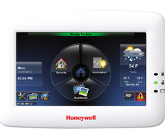
Ho
me Page
Name
D
escrip
tion
T
ime/Date
Displays current panels Time and Date
.
Setup
Accesses the Setup Menus
.
Slide Show
Accesses the Slide Show Setup
.
Traini
n
g
Videos
Access to view
o
ne of six
available
videos
.
Status Bar
Displays the current Network IP Address,
Z
-
Wav
e
Enab
led, Co
ntrol Panel, AC Power
Status of the
Resideo
Control Panel, Wi
-
Fi Signal Strength,
and SD
Card
present
.
Camera
Accesses the Camera
S
creen
.
Emergency
Acces
se
s the Emer
gency (Panic)
icons
.
Can be accessed from any screen.
Temperature
Displa
ys t
he c
urrent temperature
.
Security
Accesses the control
panel’s
security options
.
Multimedia
Accesses Camera, Event View, Picture, Video, and
M
essage Menus
.
Automati
on
Accesses
Lighting (Outputs),
Z
-
Wave device view and control
, Scene setup, Room Setu
p,
Z
-
Wav
e
setup menus.
Status
Banner
Displays
status
of the control panel
.
Microphone
No function
.
Download
Appears only when a new version of
t
he keypad is available
an
d takes pl
ace of the Setup
icon.
Download loading
Appears when the keypad
is receiv
ing a do
wnload from the server.
Setup, Slide show
setup, installation
videos
Resideo
Control Panel
Status Bann
er
Emergency
Status: Netwo
r
k IP Address,
Z
-
Wave
Enabled, Control
Panel AC power
present, Wi
-Fi signal str
ength, and SD card present
Camera Screen Shortcut
TUXEDO TOUCH WI
-FI INSTALLATION & SETUP GUIDE
13
Setup Screen
Pressing
SETUP
from the Home Page
reveals the following options:
Name
Description
Brightness
/V
o
lume
Move the
Brightnes
s/
Volume
sli
de bar up or down to increase or decrease settings
.
Pressing back without
saving
will present a
new window that displays
YES
saves
the change
or
NO
to
discard
the changes
. If
Yes
is selected
when you exit
the
keyp
ad displays
“Information Set
ti
ngs Saved
.
”
V
oice Setup
Access
the
voice configuration screen
.
S
ee
Voice Tutorial
above.
Save
After setting the Brightness and Volume to the desired settings press
Save
.
Partition
No fun
c
tion
System
Informatio
n
Reveals So
ftware Version, Network Information, Remote Upgrade options
Disp & Audio
Change t
he Operating Modes of the keypad
(Backlight
, Slideshow, etc.)
IP
Access the
IP Setup menu
.
System
Accesses
the
p
rogramming
for
advance s
y
stem settings
.
Ac
count
A
ccount Log
In Username and Passwords
(See
Web S
erver Ac
cess
s
ection for more
information
).
E
-
Mail
For configuring email notifications
System
Information
The network information is an importa
nt tool. It all
ows you to
verify th
e Software Version
, MAC Address and CRC
(Used for Total Connect), IP
Addre
ss, Broadcast Address,
NetMask
, and the option to e
nable
the r
emote
upgrade
, setup
the remote upgrade feature (see “
Software Upgrades” section
) an
d syncing the IP
to the se
rver.
For Tuxedo to receive an
update,
it needs to be c
onnected
to the internet via LAN or
WIFI.
An SD card with 200 MB of available space is required.
Software Upgrades
To view the current software
version in
stalled on you
r system, an
d verify connectivity, do the following:
Press
Setup
>
System
Info
. Th
e Interf
ace Name, Host Name, MAC Address, CRC, IP Address, Broadcast
Address, and NetMask are displayed.
NOTE
: AN SD CARD WITH 200
MB OF A
VAILABLE
SPACE IS REQUIRED.
Manu
al Software
Upgrades
1.
Go to the Toolkit site located
at:
www.tuxedotouchtoolkit.com
to dow
nload the latest software to an SD card.
An SD
card is provided
with 4GB of
available
space.
2.
Copy the software upgrade file to the SD card and power
down
the T
uxedo
, or hit
Reset
on the side, under the SD card
slot
.
3.
Insert the SD card >
power
up
the Tuxedo
, or wait for the keypad to finish rebooting if
Reset
was pressed.
Automa
tically Push
ed Updates
NOTE:
For Tuxedo to receive an update,
it needs to be connected
to
the
internet via LAN or Wi
-Fi and a
n SD card with a
minimum of
200MB
installed
.
Automatic
Feature Updates
To receive
feature update
s for
non
-c ritical
optional featur
es, check th
e box labeled
Enable Remot
e Upgrade
on the
System Information screen.
NOT
E:
Setup
changes to
Available Software Update
. This
represents a software
download
is in process.
Optional Software
Updates (From Server)
Th
e “Status Bar” will disp
lay an
ico
n for downloading in progress, once complete t
he
Setup
icon changes to
Available
Software Update
icon
. (For the Tuxedo to receive an update, it needs to be connected to the internet via
LAN or WIFI.
) TUXED
O TOUCH WI
-FI INSTALLAT
ION & SETUP GUIDE
14
The “Home” scree
n displays the
Availab
le Software
Update
icon
, representing there is an update available
.
1.
Press
Available S
oftware
Update
.
2.
Press
Software Download
to view the current software version, the new version, release date and release notes.
3.
Press
Install
Now
to begin the software up
date.
The
screen displays:
“Files downloaded successful...System will
reboot in 15 se
conds to
upgrade
the unit,”
or
press
Reboot
to start the update process.
(Pressing
Abort
.
cancels the
update
.)
4.
When the update is complete, Tuxed
o reboots and completes th
e software
update.
Critical Updates
1.
Press
Remote Upgrade Setup
to set the period
that you w
ant to upgrade the system in the Arm condition.
2.
Select the Duration Typ
e in hours or days
.
3.
Press the duration value to enter the number of
Hours (
24-1440 hours,
default is 7
20) or Days, (between 1
-60 days,
default is 30).
Press
Save
when done.
NOTE
:
Sys
tem Critical Update
s will automatically be pushed to the Tuxedo
, even in the armed state
(or in automation
mode)
upon the time interval set
. Example, if a custom
er is not on
site for more than 30 days (default), the system will
automatically updat
e and re
tain the previous system status after the update
. System status (armed or disarmed start)
will affect this update.
U
L
Automatic Push Sof
tware Updates are not f
or UL applic
ations.
Display & Audio Setup
The
Display and Audio
screen accesses the f
ollowing
options:
Operating Modes
This screen provides access
to
Chime Mode, Voice Mode,
and
Voice Chime
.
•
When in Chime Mode Tuxedo chimes whene
ver a door or window is
open.
•
When i
n Voice Mode the Tuxedo voice annunciates whenever a change in system stat
us occurs such as Armed,
Disarmed, or Alarms.
•
When in Voice Chime the chime mode and voice mode are in effect.
The chime beeps followed by voice a
nnunciation.
Press
Setu
p
>
Disp &
Audio
Setup
; enter an authorized code, if required
>
Chime Mode
or
Voice
Mode
(
t o turn
the mode on or off
) >
HOME
or
BACK
after making your selection.
IMPORTANT
:
The Chime feature is
intended for convenience
only
, it is not intended for life
safety purpo
ses or pool
alarms
, and does not meet the requirements of UL 2017.
NOTES
:
•
If the Chime Mode and Voice Mode are both selected, the Voice Chime is automatically selected.
•
When Tuxedo exit
s the “Operating Modes” screen, you
r selection is saved.
•
It may take a few seconds for the Chime Mode to take effect.
•
Certain panels do not support the Voice Chime Mode. Refer to the
Control Panel Compatibi
lity
section.
Language Selection (i
f applicable)
For future
use, the Tu
xedo
only support
s the English language.
Screen Time Outs
•
Backlight Off Af
ter X
time
(turns the backlight Off after the selected time has expired)
•
To Homepage After X
time
(returns to the “Home” screen after the selected
time has expired)
•
Auto
Slideshow Af
ter X
time
(if enabled, begins the slide show after the selected time has expired)
To select the desired screen timeouts, do the following:
1.
Press
Setup
>
Disp & Audio
SETUP
; enter an authorized code, if required.
2.
Pre
ss the desired selection
from the dr
op-down list displaying the amount of time
for each option (Never, 30
-seco
nds
and
1, 2
, 5 and 10 minutes) p
ress
Save
.
If changes are made and
press
Save
, a pop
-up window displays:
“Information Settings Saved”
and
exits t
o the home
page.
NOTE
Pre
ssing
Back
without saving will display
“
Aui Setup Changed.
Do you want to save it?
Yes or No. Yes
saves the changes.
No
discards the change.
TUXEDO TOUCH WI
-FI INSTALLATION & SETUP GUIDE
15
Temperature
Unit
The temperature units for the weather display on Tuxedo’s home scre
en can be switched betwe
en Fahrenhei
t and
Celsius.
Setup
>
Disp & Audio Setup
and
enter an authorized code.
Select t
he temperature scale,
Celsius
or
Fahrenheit.
Clean Screen
With the exception of normal cleaning, the keypad
is maintenance free.
Press
Se
tup
>
Disp & Audio
Setup
>
CLEAN
SCREEN
.
A pop
-up window displays
"
Touch Screen has been
disabled so that
you may
wipe the screen clean.
Ple
ase use a damp, soft cloth.
DO NOT use any liquids, sprays, or
ammonia-based cleansers.
Press CONTINUE to di
sable touchscreen
."
*Pan
ics cannot b
e initiated during this process*
Press
Continue
or
Cancel
to exit or press
Save
.
NOTE:
When
Cont
inue
is pressed the message
"
Touch Screen Disabled for 30 Seconds
"
is displayed.
During these 30
seconds,
the touch screen s
hould be wiped clean of
fingerprint
s using a mild soap solution and a soft cloth.
When
the counter reaches z
ero, the
window
automatically closes and the touch screen is active.
IMPORTANT:
Do not use an abrasive cleaning agent or abrasive cloth when clea
ning Tuxedo or damage to
the touch
-
screen may occur.
The
Emergency
screen cannot be acces
sed whi
le running in the clean screen mode.
IP (Setup
)
This section allows you do an initial connection to the Wi
-Fi network, or if netwo
rk change has occurred (
i.e. SSID
change, Security Mode, or Passphrase/Shared Key).
Setting up a LAN (non
-Wi
-Fi) conn
ection
in DHCP mode will
automatically populate the required network information (I
P Address, Subnet Mask, Default Gateway and DNS Server)
.
NOTE
:
These fields ar
e not editab
le. To change the network type to static press the
Internet Connection Ty
pe
from
Dyn
amic IP to Static IP. Once, this is done the fields are now editable.
Wi
-Fi Setup
DHCP Setup
By
default,
the keypad is configured for D
HCP. Once accessing
IP
, a list of available network will display. Choo
se the
desired network and enter the followin
g information:
Required Field
Description
SSID
Network Name
Security Mode
The keypad will automatically detect the security mode of the
r
outer
Passphrase/Share
d
Key
Passwo
rd to access the network
Manual Network Setup
The option to add a custom
network
is available by selecting
Add Network
. Connection to this mode requires the
information
in the “Required Field”
column
in the
table above
. Press
Save
when compl
eted.
Static
Network
The option for a Static Network
is only available once you
have connected
using DHCP, when using a
Wi
-Fi
connection.
After connecting to a
Wi
-Fi
network
, select the connected network from the list. The next sc
reen reveals the network
details.
Press
the
“Internet Connection Type”
option to allow the IP Address,
Subnet
Mask, D
efault Gateway and DNS
Server
fields editable.
Port Settings
The Port number (
PORT
#
) listed on the bottom right corner of the screen is r
equired
when port forwardi
ng is bein
g
configured.
To change the default port number (6280)
settings,
perform
the foll
owing steps
:
1.
Press the numerical value
next to
Port #
and enter a secondary port number (
between 5000
– 65534).
2.
A pop
-up window displays t
he message
:
“
Port number
changed. K
eypad is going to reset.”
3.
At your PC, Smart Phone or Tablet bro
wser, start
your br
owser and enter your IP Address.
Refer to the
Remote Access
section for further details.
TUXED
O TOUCH WI
-FI INSTALLAT
ION & SETUP GUIDE
16
Webserver Access
Sup
ported Browsers
System Re
q
uirements
Recommended B
ro
wser
Wind
ows XP SP2 and SP3, Win7,
Win8
IE 8.0 and above, Chrome 30
-
42
, Safari 5.
0.2 &
ab
ove, Mozilla 26 and above.
Android Mobile
ICS4.0 and above
iPad™, iPhone™
Default browser (iPh
one Version iOS4, iPad® Version
iOS4 and i
O
S5, iOS6)
Android Tabl
et
Default b
rowser (Galaxy
–
Android 2.3)
Win 8 tablet
Default browser
Other tablets
, smart
phones
Might face some issues because it is not possible to
support all browsers.
NOTE
S
:
•
If JavaScript is disabled in any of the browse
rs then
some of the feat
ur es will no
t be populate and functions may not
work.
•
If the “Load Images” option is d
isabled
on a smart device’s mobile browser, then images will
not be populate on the
pages.
•
Google Chrome version 42
and higher
do not support the
QuickTime plug in; video
streaming w
ill not work. This is
the same
with Android Devices.
IMPORTANT
:
Use the web brow
ser to view cameras for non
-security purposes only.
Camera streams viewed from the
web browser can stop without ind
ication due to network
connection issues.
Inte
rnet Explore
r 11
Note:
If the video streaming is not working, configure the browser fo
r compat
ibility mode and
refreshed the web page.
Supported Router
s
NOTES:
•
Tuxedo Wi
-Fi is not compatible with Linksys
Cisco routers Model: WRT4GL
v1.1 Wireless-G
broadband
router.
•
In most cases, IP addresses are assigned
‘automatically’ (DHCP). Alternatively
, you may
require a “Static” (Fixed) IP Address that can be
found by accessing your router. Refer to your
router instructions.
Manufact
urer Name
Device Name
D
-
L
ink
DIR
-
63
2 Router
Netgear
WNR2000V3 Router
Actiontec (Verizon FiOS Router)
MI424W
R Router
Apple
Apple AirPort Router
Almond
Securifi Almond.
Netgear
Netgear R7000
ASUS
ASUS RTN66U
Netgear
Netgear N900
Netgear
Netgear
Ne
tgear
Netgear
Dlink
Sha
report
ASU
S
ASUS
Local Access
Tuxedo’s remote access option offers built
-in web hosting
capability to access your system via any web enabled device.
Tuxedo can connect to a network router via Ethernet cable (LAN network) or vi
a Wi
-Fi depending on th
e installati
on
pre
ference.
The
Account Login
menu accesses the username and password used to for the connection. This can be a
local connection or remote connection using port forwarding. Features of this page are as follows:
•
5 t
otal users
•
Enabling or d
isabling
aut hentic
ation for
web
server
local access
•
Secure web server access
(HTTPS) TUXEDO TOUCH WI
-FI INSTALLATION & SETUP GUIDE
17
Web Server IP Address Access
The Home screen reveals the connected IP address in the bottom left hand corner. Any device with a browser connecte
d
to the same networ
k as
the Tuxedo can access the webserver. This does not require authentication (Username and
Password). If this authentication is desired, check the
Authentication for Web Server Local Access
check box, which
can control who has acces
s to connect
by requirin
g a
username
and password
. Unchecking the box leaves the Web
Server open for anyone t
o connec
t.
Connecting the Tuxedo to a mobile device
To connect a mobile device to Tuxedo, view the
Local System Control (Tablet/Smartphone)
trai
ning video, and then do
the followin
g:
Smart Phone or Tablet
1.
Verify the Tuxedo is connected to the Internet vi
a Wi
-Fi
or its Ethernet connector.
2.
Verify the
Smart Phone
, or Tablet
, is connected to the same network as the Tuxedo Wi
-Fi (disable mobile data if
needed
.)
3.
Open the brows
er and enter
the IP Address on the keypad (described above).
On a Personal Computer (P
C)
1.
Verif
y the Tuxedo is connected to the Internet via Wi
-Fi or its Ethernet connector.
2.
Verify the
PC
is connected to the same network as the Tu
xed
o Wi
-Fi.
3.
Open the browser
and enter
the IP Address on the keypad (described above).
Remote Access
Browser
Comm
ands
Access
to basic arming commands is available if using a Smart Phone or Tablet bro
wser.
Full access to keypad options is
available if using a
PC
.
NOTE
S
:
•
If left ina
ctive, the w
eb connection will disconnect after 10 minutes.
•
If using an iPad, iPhone o
r PC bro
wser with low band
width on the mobile PC type theme, switch to the mobile
theme.
To switch to the mobile theme
press
Switch Theme
in th
e lower left hand corner
.
Not suppor
ted command
s during remote or local access w
ith a web browser in PC or Mob
ile Mode
s:
Security
Annunciate status
Multimedia
Message center
System troubles
Picture/slide show
Emergency button
C
amera 360 degre
e
rotation
Event logs
Camera W
i
-
Fi settings
Show zones
Recording settings
Automation
Z
-
W
ave dev
ice management
Setup
Account setup
Emergency button
Disp
.
& Audio setup
Rooms
IP setup
Remote scenes
S
ystem setup
Email setup
General
We
ather
V
oice setup
Traini
n
g videos
Remote firmware upgrade
TUXED
O TOUCH WI
-FI INSTALLAT
ION & SETUP GUIDE
18
Local Web Serve
r URL Ac
cess
In cases where the Tuxedo is set for DHCP, there is the possibility the IP address can change upon a router reset. This
can block th
e users attempt to access
the Web Server locally. To correct this problem,
navigate to the “
Address Box
” of
the brows
er and
type in HTTP://Tux.MyLanConnect.com
. The browser will display
the following inform
atio
n:
Description
MAC Addr
es
s
Device N
ame
Internal IP
TUXW_
XX.XX.XX
00D02DXXXXX
Master Bedroom Keypad
192.168.1.120
TU
XW_
XX.XX.XX
00D02DXXXXX
Garage Entry Keypad
192.168.1
.110
TUXW_
XX.XX.XX
00D02DXXXXX
Front Door Foyer Keypad
192.168.1.112
Troubleshootin
g
If the page does not p
opulate, fro
m the Home Screen
press
Setup
>
System
Setup
>
System
Information
.
1.
Pres
s
Sync IP to Server
.
2.
The message
“
Sy
stem IP sync to server is
successful
,”
when a successful connection is made.
3.
If no connection is present
, the
message
Keypad is not in t
he
network.
Please check the network connectivity.
”
4.
If the keypad is connected to the
LAN with no internet access, the message
“
System IP sync to server has failed
”
appears.
If Authentication for Web Server Loc
al Access is enabled,
and no user name and pa
ssword is created, the browser will
produce the following message:
“
Warning Remote ac
cess has
been deactivated. Go to your Tuxedo’s login setup
to create an account for remote access.”
NOTES:
•
To correct this
add a username/passwo
rd and verify the user i
s enabled.
•
Browser may block access if the Secured Web Server Access (https) option is
enabled
. During remote login, if the
browser displays a Security/
Certificate
Error (see examples below) this is not a thre
at and
it is recommend
ed that
you continue.
Remote A
ccess Using Port Forwarding
Tuxedo offers built
-in web hosting capability to acces
s your syste
m via any web enabled device.
The local
IP Address is
used on a standard web browser to control user functions.
The home rou
ter must first be configur
ed for por
t forwarding
for both HTTP and HTTPS ports
, which port the local IP addres
s. Refe
r to the router’s instructions for details on Port
forwarding. See
the
notes above for
any
security certificate errors
and
steps to be ta
ken
to proceed.
Remote A
cc
ess Log In
Setup (Account Setup)
The home router must first be configured for port forwardi
ng for both HTTP and HTTPS ports.
Refer to the router’s
instructions for details for instructions concerning
port forwarding.
You can as
sign up to five user login
s. The Tu
xedo can determine when there i
s a local or remote (port forwarded)
sessio
n. If d
etermined it is a remote session
a username and password
are
required
To set up a remote access log in, do the following:
1. Pre
ss
Accou
nt Setup
.
2. Enter the de
sired user
name and password.
NOTE:
Passwords must be
eight
alphanumeric character
s, inclu
de at least one uppercase letter and one number.
3. Check the box for
Secured Remote Access
(HTTPS)
(optio
nal)
>
Save.
A
confirmat
ion window displays the me
ssage
,
“Se
ttings Saved.”
The new user is displayed
along with an
Enabled
button, i
f there is no network connection the icon
will change to
Disabled
.
4. To clear a user’s login, press
Clear
.
NOTES
•
Remote login is blocked after t
hree failed attempts. T
o restore, o
n the keypad click
Setup
>
Account
, press the
appropriate
user
Disabled
icon
>
Sav
e
.
•
If left inactive, Web connections disconnect after 10 minutes.
Email Setup
TUXEDO TOUCH WI
-FI INSTALLATION & SETUP GUIDE
19
Email
notifications
allow you to set up email accounts
and receive email notifi
cations when
one or more system events
occur.
Users (and/or the installer) can receiv
e email notifications when one or more selected system events or conditions occur
NOTE
:
Email notification requires that the user has an active em
ail address and note the
disclaimer
at the bottom of the
page.
“Email notification is strictly for convenience use on
ly.
Avoid relying on this feature for life critical events.
It is
not UL certified and may fail at any time
without notice.
”
NOTES:
•
Ema
il notification requires
that you ha
ve an active email address.
•
An SMTP account needs to be assigned to establ
ish the
email server domain (i.e., the “from” address).
•
Four
programmable sets of events (labeled “Event 1 –
Event 4”).
•
Each event 1
-4 can send em
ail notifications to up to
four emai
l addresses.
•
Seven
event types and corresponding conditions
can trigger a
n email.
For each event 1
-4, choose the conditions that will trigger notification:
User Email Setup
1. To
set up an email notification, from the H
ome screen, press
Setup
>
Email
.
2. Select the
User SMTP
icon
to set up the user’s email server informati
on (user
domain/server, which provides the
“from” email address).
a. Select the email server name (email provider).
Choose from
GMAIL, OUTLOOK, YAHOO,
or
Add New
E-mail
Server
.
b. Enter the
E
mail ID (
User
name)
and
Password
for the chosen email server on the
appropriate lines.
c. The Email Server and SMTP port number f
ields are automatically filled unless “Add new email server” was
select
ed.
If
Add new
E-M
ail S
erv
er
was selected, enter the email server SMTP and port number information (
see your
email
provider for details).
To change the “E
-Mail Server Name,
” press
Edit
and enter a new server name.
Enter an “E-Mail ID” and passw
ord.
Enter the “E-Mail
Server” add
ress and “SMTP Port Number.”
If required
by the
e-mail service provider,
click on
the box next to
USE SECURE CONNECTION (SSL)
.
d.
Press
Save
.
3. Press
Event 1
to define the desired event notifications to be sent
(S ee “Defining Event Type
s” section b
elow.)
Select
the desired event types and conditions for this Event and p
ress
Sav
e
.
4. Enter the email
address
(es) to which Event 1 will send a notification; press
Save
when done.
User notifications are
restricted to o
ne SMTP
(from)
email add
ress.
Repeat
steps
three
& four
for Events 2
-4 if desired.
5.
Press
E-MAIL LOG to view
the em
ail log; press
CLEAR LOG
to remove the email log.
Dealer Notification
s (Automation Mode Only)
If Dealer
notifications are desired, press
D
ealer Setup
to assign th
e “Dealer Email
.” “Dealer SMTP” and “Dealer
Code” then follow the steps abov
e to pro
gram eve
nt notifications.
Dealer notifications are restricted to one email
address.
NOTE
: Dealer Notifications are only accessible when keypad i
s configured in “Automat
ion Mode.”
Dealer Cod
e
Press the
Dealer
Code
icon
and enter the
New
Code; Confirm New Code
and
press
Save
when done
.
The dealer can choose to save the Dealer Email and Dealer SMTP to the SD Card by selecting
Save conf to SD
Card
.
The dealer can use the S
D Card with the saved configuration and apply to an
other keypad by selecting
Load conf
from
SD
Card
. Press
Save
when done.
U
L
Email Notifications are supplementary only and not evaluated for
UL applications.
TUXED
O TOUCH WI
-FI INSTALLAT
ION & SETUP GUIDE
20
Defining Event Types
To receive email notif
ication when
specific events occur,
the
“event type” must be defined.
Scenes can be set to tr
igger
based on the status of these settings.
From “System Events Notification” screen, set the following event types:
Event
Definition
Security
(Normal mode; cu
rr
ent home p
artition only.)
Pres
s the desired check box next to
Disarm
,
Arm
Away
Secu
red
,
Arm
Stay
and/or
Alarm
.
Zones
(Normal mode; current home partition only.
)
Press the desired check box next to
Alarm
,
Trouble
,
an
d
/or
Restore
.
Occupancy (automation
m
ode only)
Press the desired che
ck box next to
Home
,
Away
and/or
Night
.
NOTE
:
If in Commerci
al mode, the
occupancy options are
Open
,
Close
, and
Night
.
Thermostat
Select a thermostat from the drop
-
down list.
Press the desired che
c
k box next to
TEMP ABOV
E /
TEMP
BEL
OW
. Enter the temper
ature degree that triggers an Email when the temperature rise
s
above or falls below the set point.
Door Lock
Select the desired door lock from the drop
-down list. Press the desired check box next t
o
UNLOCKED
and/or
LOCKED
.
Garage Door
Select the desired
garage door from the drop
-
down list. Press the desi
red chec
k box next to
CLOSED
,
OPENED
and
OPERATION DISABLED/F
AILED
.
Water Valve
Select the desired water valve from the drop
-
down list. Press th
e
desired check box next
t
o
OPEN
ED
a
nd/or
CLOSED
.
WARNI
NG
: The Leak Gopher® water valve does not send status
to the
keypad when operated
manually. It is not recommended to select this device as an Email trigger.
Recording
Select an Email address and hi
g
hlight
Recording
. Enab
le
the desir
ed check box next to
“On Event
Recording
”
and/or
“
SD
Card
Memory
Full
.”
N
OTE
: An
SD Card Full Message displays when 90% of the usable space on the SD card is used.
NOTE
: An SD Card Full Message displays when 90% of th
e usable space on the SD
card is use
d.
Troublesh
ooting
•
If an error is returned through the listed SMTP email p
rovider
stating that the email has blocked a sign in
attempt, return to the SMTP server page and verify t
he email settings. The Tuxedo will popul
ate an error that
states
“Warning: E
mail sending failed. Please check SMTP settings.”
If this is the case, c
heck the
security
settings for the email chosen through the provider.
•
The customers email server may see
a frequently sent message and could perce
ive it as a threat. The
result is
the email provider will lock down the email receive and send. You will hav
e to con
tact their email provider to
resolve.
TUXEDO TOUCH WI
-FI INSTALLATION & SETUP GUIDE
21
System
Setup
The
System menu is compromised of the following
options:
Menu
Description
Controller
Initial Set
Walks throu
gh
the initi
al setup (same as first time power up or
keypad default)
. See
the
“First
Time Set
up”
section.
Quick Programming
Setup
Installer menu programming (vs. using console mode)
Tuxedo Sync
An advanced Z
-
Wave function (See t
h
e
“
Z
-
Wave”
sec
tion)
Us
er
Profile
S
ee
“Important Operation Information”
s
ection for more details
CS Setup
In
staller
level Setup and Troubleshooting tools
User Setup
Setting up User Codes wit
h the Tuxedo
Advanced Setup
Access to advanced Installer/User
o
ptions
Time/Date Setup
C
onfigure t
he time and date
Power Mode Setup
Program how the keypad reacts during a
power ou
tage
Quick Programming
The Quick Programming section gives the installer o
ptions to program the basics of the control panel.
To access Q
uick
select the
Quick
Prog
ramming
bu
tton: the screen displays a
Confirmation
message
“
Not every security panel
support
s
quick programming
. Check the panel’s documentation to make sure it supports quick programming.
Choose Abort if
the panel does not supp
ort it or Continue to en
ter quick pr
ogramming.
Choosing Continue on unsupported panels
may result in this device rese
tting.
Continue
or
Abort
.”
Select
Continue
, and then enter an auth
orized code.
An
Information
message is displayed
“
Panel is entering
programming mode, pleas
e wait...
”
•
Fol
low the menus and prompts to program the control panel.
•
Only the residenti
al panel
s support the Quick Programming mode.
Quick Programming Menu’s
Menu
Programming Locations
Phone Account
Primary and secondary phone and a
c
count number for partit
io
ns 1 and 2
.
Reporting
Select Yes or No for Alarm Restore, Trouble, Bypass, AC Loss,
Low Bat
tery, Test,
RF Low battery, or select
All
to enable all events
.
System Reports
RF Jam, Log Full, Open Report, Close Away, Close Stay, Can
c
el, Exit Error, All
.
T
im
ing & Misc
Exit Delay, Entry Delay 1, Entry Delay 2, Installer Code, Auto Stay, Alar
m Sound
Time,
and Fire
Sounder Time Out
.
Zone Programming
Send Report
, Input Type, Library (Vocabulary), Part (Partition), Resp (Response
Time),
C
onfig (Hardwire Type)
.
TUXED
O TOUCH WI
-FI INSTALLAT
ION & SETUP GUIDE
22
CS Setup (Central Station)
Menu
Programming Locations
(Press
Setup
>
System Setup
>
CS Se
tup
; enter
the
Installer Code)
ECP
Addr
ess
Configure the Tuxedo ECP
and RIS address
(see the
“2
:
Set ECP Address/
R
IS
Automation Address”
section).
Options
The configuration options are:
Options
Description
Lighting
Unch
ecking t
he box will eliminate th
e
output
control for the panel option
, located
under
“Automation.
” Leaving it checked enables the
option, see
“Outpu
t Setup Function
”
EN50131
Display
See the “Blank Display” feature under
the
“Ab
out the System”
section for more information
Weather
Forecast
Unchecking the box disables the Weather
Forecast from the home page. For s
etup
instruction,
see th
e
“Weather F
orecast”
section.
Commercial
Only available in Automation Mode. See the
“1:
Oper
ational Mode Setup
”
Operating
Modes
Options are
Nor
mal
Mode
,
Safe
Mode
,
De
m
o
Mode
, and
Automation
Mode
. See the
“1:
Oper
at
ional Mode
Setu
p.”
Time/Date Setup
If not already set from the control panel, set the current
time and date using the
Time/Date Setup
menu
access by
pressing
Setup
>
System
Setup
>
Tim
e/Date Setup
. When the time is set it is stor
ed in Tuxedo
, it is sent
to the
cont
rol panel when you press
Apply
and answer
Yes
. Additionally, when using t
he
Tuxed
o, the panel may download its
time into Tuxedo periodically after the clock is set (for Vista Plus series and newer commercial panels such
as Vista
Turbo series).
Pressing
Ge
t Time
downloads the time, date from the control panel,
and exits the Set Time & D
ate screen.
NOTE
:
This
with VISTA Plus series controls and may not appear with all VISTA Turbo controls
.
To set the current time, do th
e following:
1.
Press
Time/
Da
te Setup
and enter your Authorized Code.
2.
Press the
M
onth
"drop down
," and select the curre
nt month.
3.
Press the displayed
Year / Hour / Minutes
and enter the current year/hour/minute(s).
Select
AM
or
PM
. (Each
depression
toggles
the AM/PM display).
4.
Pre
ss
the
MMDDY
Y
“drop down
,” and select a format for which you want the date to be displ
ayed.
5.
Se
lect a 12-hour or 24
-hour format for your time display by checking the box to the left of the
12 Hour
display.
NOTE: Checked sets it for 1
2-hour format, unchecke
d sets it fo
r 24
-hours format.
6.
Press
DST
to enable daylight saving time in your syst
em clock
. Set the “Start DST” time and then the “End
DST” time by selecting the appropriate
Month, Weekend
and
Hour
that DST starts and ends.
7.
Pre
ss
Apply
, a confirmatio
n screen ap
pears
.
Yes
,
saves the time changes in your security system.
No
saves
the
changes
to the Tuxedo only.
Code
Authority
The
Code Authority
screen displays User Names
and Par
tition Authority Level for the User Code.
To view
the Code Authority level, do the following:
Press
CS Setup
> enter
authorized code
>
Code Authority
> Enter
the 4
-digit
User Code for
the user that you want to obtain Authority Level informatio
n about
>
BACK
.
NO
TE
:
If the User Code entered is not active in the system, an
INVALID
message will be displayed.
Device
Events
Tuxedo has the ab
i
lity to record events i
n
a history
log.
Each event is recorded with the time and
date of its occurrence.
Press
Devi
ce
Events
and a list of events is displayed.
To view a record of events in a history log, slide the scroll bar down
. The Date, Time and
Description of each eve
nt
is displa
yed.
TUXEDO TOUCH WI
-FI INSTALLATION & SETUP GUIDE
23
NOTE
S
:
•
A
Yes
response is recommended.
•
Getting t
ime f
rom the internet feature is only supported in
Automation Mode.
•
After each selection, the wi
ndow close
s automatically and the selection is displayed.
User Codes
Each user must be assig
ned a name with a corresponding 4
-digit user code in order to gain acce
ss to various features and
functions.
Tuxedo can hold the identity
for 10 Users in its mem
ory. If additional Users are needed, define the additional
Users using the Console Em
ulation
Mode.
Users for the system are programmed in a central user setup locat
ion that provides the specific questions for
authorization levels a
ssigned to different users
. You may
want these users to be the same, but there are situations in
which you ma
y want a
user to have limited capabilities.
These capabilities are defined by
the Authority Level assigned
to each user.
Authority Levels
Author
ity levels define the sy
stem functio
ns a particular user can perform.
Depending on the authority assigned to
you,
the
re are certain system functions you may be prohibited from performing.
The following information describes the
authority levels available
in Tuxedo and provides th
e equivale
nt authority level name found in your alarm system
manuals.
The authority
levels
available in Tuxedo are as follows:
Keypad
Authority
Level
Functions
Equivalent System Name
Residential
Systems
Commercial
Systems
In
s
taller
Can perform all
se
curity fun
ctions except can only
disarm if code was used to arm, can change Master
Code, can
not change other user codes, can access the
Central Station Screen op
tions.
NOTE
:
This authority level cannot be assigned using
the keypad
.
Installer
Installer
M
as
ter
Can pe
rform all security functions, add/delete users in
assigned partition, prog
ram sche
duled events, and
change partition master code.
Partition
Master
Level 1
Master
Normal
Perform security functions (arm, disarm)
Standard
U
ser
Level 3
Operator A
Guest
Can
arm the system in assigned partitions, but cannot
disarm the system unless
the sys
tem was armed with
this code.
Note
:
Do not assign this level if Q
uick Arm is enabled
in the system.
Guest
Level 4
Operator B
No Access
U
s
ed to restrict access t
o
a partitio
n.
N/A
N/A
NOTE
:
The authorized code for deleting, adding, and editing us
ers is d
ependent upon the interfacing
alarm panel
. Check
your alarm panel
Installation and Setup Guide
to determine who can delete, add, and edit
users
.
Add a User
From
the "Home" s
creen, press
Setup
>
System Setup
.
1.
Press the
USER SETUP
>
ADD USER
> ente
r your authorized code.
Press the box next to
Enter User
Name
and type in the user name (max. 6 characters; no spaces between characters)
press
OK
.
2.
Press the bo
x next to
Us
er Number
and e
nter an “available” (3-digit) user number; p
ress
OK
.
3.
Press
the box
next to
Enter User Code
, enter the 4
-digit User Code for this user and press
OK
.
4.
Press the box next to
RF Button Zone
(if used);
enter t
he 3
-digit RF Button Zon
e for this u
ser.
5.
Press
Save
.
NOTES:
•
For available user numbers, refer to the control
panel i
nstructions.
•
If assigning this user to wireless key, enter one of the zone numbers of the keyfob (the wireless key must be
programmed firs
t before it can be assig
ne
d to a use
r).
•
Each user programmed by an a
uthorized code (in most cases, this is use
r two in
most cases.
) This means that user
two
(or
whichever
code you are using to program the users)
cannot
be assigned to a user in the keypad
. TUXED
O TOUCH WI
-FI INSTALLAT
ION & SETUP GUIDE
24
How to Add an Existing Us
er to a Se
cond Tuxedo
After adding a user
to the first Tuxedo, the same user can be added to
a second Tuxedo.
From the second Tuxedo go to
User Setup
and enter the same user name and same user code (refer to “
How to Add a User
” a
bove).
The second Tuxed
o
will autom
atically update the user info
rmation.
Press
Save
.
Delete a User
Select th
e User y
ou want to delete and press
DELETE USER
. Enter your authorized code, and press the appropriate
icon.
Edit a User
NOTE:
You cannot edit
a User name or User numb
er. To modi
fy a User name or Us
er number, you must delete the User
and re
-enter the U
ser. Ed
it a User as follows:
Press
EDIT USER
and enter your authorized code.
Select the options needed for this user and press
Save
.
Advanced
Setup
Access these menu
s from the
Home
screen, press
Setup
>
System
Setup
>
Advanced
Setup
. If applica
ble
,
ent
er your authorized code and press
Keypad
Test
.
Keypad Test lets you verify correct operation of the Tuxedo and its connections to the s
ecurity system.
There a
re five
diag
nostic test
s:
•
LCD Display Test
•
Audi
o Test
•
LED Test
•
Calibration
•
Z-Wave Test
NOT
E
:
Performing Diagnostic Tests
: Select any diagnostic test from the “
Diagnostics
” screen by pressing its associated
Test
icon.
All or any
individual test may be ru
n when you
access the “
Diagnostics
” screen; however, each test must be
performed one
at a ti
me.
At any time when a test is not being performed, you can press back to return to the previous
screen
or home
to return to your home pa
ge.
Once
the Diagnostics screen is
exited, subsequent entry to this screen displays
all tes
t options as
"Not Performed."
LCD Display Test
Press
LCD Display Test
; a series of screens appear.
After each type of display, you are
asked if the display wa
s proper.
If the respons
e to all questions is yes, the LCD
Display Test message area
of the D
iagnostics screen displays
Passed.
The
Emergency
screen cannot be accessed while running the LCD Display Test
.
Audio Test
Press
Aud
io Test
;
Tes
ting
..
is displayed while beeps sound from the speaker.
At the conclusion
of the test, a pop
-up
"Confirmation Window" is displayed with the question
Did you hear Beeping
?
•
When you press
Yes
, "
Passed
" is displayed in the
test status column on t
he
"Diagnost
ics" screen.
•
When you press
No
, "
Failed
" is displayed in the test status c
olumn on
the "Diagnostics" screen.
LED Test
Press
LED Test
; "
Testing
...”
is displayed while the 3 LEDs light sequentially, top to bottom (red, gre
en, yel
low), 5 times.
At the conclu
sion of the test, a pop
-up "Confirmation Window" is displayed with the que
stion
"D
id you see chasing LED
pattern?"
•
If you press Yes, "
Passed
" is displayed in the test status column on the "Diagnostics" screen.
•
If you pre
ss No,
"
Failed
" is disp
layed in the
test status column on the "Diagnostics" screen.
TUXEDO TOUCH WI
-FI INSTALLATION & SETUP GUIDE
25
Calibration
Press
Calib
ration
and using a stylus, follow the screen directions by pressing a series of crosshairs (
+
) and boxes (
) on
the screen until done.
If the te
st was successful, press
OK
, the screen returns to the Keypad Test screen.
A pop
-up message displays
Touch scr
een cali
bration
...
Touch crosshair to calibrate.
If the Calibration Test was successful, a confirmation screen appears stating:
Congra
tulations Calibration Success
If the test was unsuccessful, an error message appea
rs stating:
Calibration failed, do you want to retry?
Yes or No.
Z-Wave Test
This procedure is fo
r Z-Wave test purposes o
nl y.
Role s
hifting is the process of shifting primar
y and secondary keypads (controll
ers).
The secondary controller becomes
the primary controller with the ability to enroll Z
-Wave devices.
This is useful when the primary control
ler is in a fixed
locati
on
and the Z
-wave device is not easily accessible (bu
t within
Z-Wave range).
To perf
orm the role shifting Z
-Wave Test, do the following:
Press
Z-wave Test
. Select from two main categories of tests:
•
Z-Wave Role Shifting:
Primary
Controller shift to Second
ary and Se
condary Controller shift to Primary.
•
Z-Wave Basic Command:
Set On or Off.
•
Assign R
outer:
Manually assign new Z
-Wave routes.
With the status of the controller in the
“
P
”
(Primary) state
, press
Z-Wave Primary.
Controller S
hift to Secondary
.
To
shift the pr
imar
y controller role to a handheld controller
(software or second Tuxedo)
; follow
the
controller
manufacturer’s instructions.
1.
Press
Z-Wave Primary Controller Shift to Secondary
on the primary Tuxedo (or software, hand h
eld device
when shiftin
g role
back
to the Tuxedo.
)
2.
Press
Z-Wave Secondary Controller Shift to Primary
on the secondar
y Tuxedo (or software, hand held device
) to
shift role from the
secondary
Tuxedo.)
A pop
-up window is displayed with the following
”R
ole S
hift is in progress, ple
ase wait ...
”
This Z
-Wave controller shift function is for evaluation only now.
This
primary
controller is shifting to the secondary.
The shift is completed when the pop
-up window disappears
.
When the pop
-up message disappears an
d controllers have shift
ed successfu
lly, Z
-Wave devices can be enrolled from this
controller.
Once complete, s
hift th
e Tuxedo back to the primary controller after enrolling Z
-wave devices.
NOTE
S
:
•
The
status of the controller can only be changed from
Prim
ary
to
Secondary
cont
roller when no devices
are enrolled.
Use the delete device or reset controller functi
on to re
move enrolled devices.
•
Z-Wave Primary Controller Shift to Secondary
is inactive when the Tuxedo keypad becomes the secondary
controller
, and the same when shifti
ng
roles aga
in.
Select
Z-Wave Basic Command Set On
to turn o
n all lamp modules, dimmer
On/Off
switches and receptacles.
NOTES
:
•
This command does not control door locks
, garage doors,
or any other security enabled devices.
•
This test
may cause lights and th
ermostat set
tings to change.
Select
Z-Wave Basic Command Set Off
to turn Off all lamp
modules
, dimmer On/Off switches and receptacles.
NOTE
:
This test may cause lights and thermostat settings to change.
Assign Router
This option gi
ves you
the abilit
y to c
ha
nge the ro
ute from one device, through a repeating device (router), to the next
devi
ce. Thi
s is u
seful for troubleshooting problematic devices. The
screen
displays
:
Box 1
Box 2
Results
Default Display
Assign Router
2
3
Test R
e
sult
Press
Box 1
> ent
er
the first
device in
Box 2
>
Assign Router
2
5
Transmit Start
Success full rout
e
change
displays
Assign Router
2
5
Transmit Complete
Unsuccessful route change di
s
play
s
Assign Router
2
5
Transmit no ACK
TUXED
O TOUCH WI
-FI INSTALLAT
ION & SETUP GUIDE
26
Keypad Reset
Pres
s the
Keypad Reset
; the
message is displayed
“
Confirmation
Are you sure you want to reset?
”
Select
Yes
or
No
.
NOT
E
: This is
not
a factory default, bu
t simply an
option to reboot the keypad.
End User License Agreement (EULA)
To review the EULA, you can
choose
“End
-User Licens
e
Agreement
.”
Factory Default
To return the keypad to factory defaults
, press the
foll
owing
Fa
ctory Default
. The message
displays,
“
Are
you sure you want to restore the Tuxedo device to
factory
defaults?
All settings will be e
rase
d and the
keypad will re
set!”
If
Yes
is selected, Tuxedo reboots
and
reverts
to factory default settings.
This doe
s not default any installed Z
-Wave devices, but does remove their names and any scenes
,
groups and rooms
that may
have been created. Wri
te down the names of each device and the
configuration of each scene
and detailed info
rmation
about the groups and room
s
.
Output Setup
Tuxedo can activate/deactivate up to 18 pre
-defined control panel output functions (if programme
d in the control panel).
The Output
Setup screen displays Output selections.
Control these output functions by enabl
ing/disabling as follows:
Press
Output Setup
> select the outputs to display or not display on the Output screen
>
Apply
. A
confirma
tion window
displays
Inf
or mation Set
tings saved
Press
OK
to save the setting
.
If the
Back
is pressed, a co
nfirmati
on window displays
“
Output Settings changed.
Do you want to save new
settings?
”
Select
Yes
or
No
.
NOTE
:
This is a local setting for the g
raphic keypad.
If user
has the max
imum number of keypa
ds on the system, and
wants to disable the same output
for all
, each Tuxedo needs to be set individually.
Night
Setup Function
The
NIGHT
function can be set to arm the system in one of five arming mod
es:
•
Away
- Arms all zone
s with entry
delay.
•
Stay
- Arms perimeter zones with entry delay.
•
Instant
- Arms perim
eter zon
es without entry delay.
•
Night
(Residential Panels Only) –
Arms all perimeter zones
. All interior zones are also bypassed, except for thos
e
zones
programmed in z
on
e list fiv
e.
•
Maximum
- Arms all zones without entry delay.
Not to be used for ANSI/
SIA CP
-0 1 installations.
To set the
NIGHT
function, do the following:
Select the arming mode to be activated when
NIGHT
is selected on the "Armin
g" screen
.
Apply
accepts
the
setting
.
Back
cancels your selection.
TUXEDO TOUCH WI
-FI INSTALLATION & SETUP GUIDE
27
Power Mode Setup
Power Mode allows you
to redu
ce power consumption in the event of a system trouble such as AC Loss or Panel Low
Battery.
Select
Power Save Mode
to enable; then choose
Turn
-off Network, or Over
ride Displ
ay Settings.
Press
Apply
to save settings.
AC Loss Notes
When
Override
Display
Settings
is selected, Display settings are overwritten and Tuxedo operates in
low power mode
:
•
Brightness/Volume controls decrease to min
imum levels.
•
Return to H
om
epage Afte
r time res
ets to 30 seconds.
•
Auto Slideshow After time reverts to Never.
•
When AC power is restored, the original Display settings resume.
•
The
device will disable the Network if it is configured.
•
AC loss changes are not s
upported in safe mode.
Mu
ltimedia
Picture
& Slide Show
Setup
Tuxedo can display personal photo(
s) on the Hom
e screen
as wallpaper or in a slide show format.
To set up a slide show
of pictures, do the following:
1.
Insert your personal media (SD/SDHC) ca
rd (with stored picture
files)
. Fo
rmats supported are .bmp, .
png or .jpg files.
2.
From the Hom
e screen
, pre
ss
Multi
-Media
>
Picture
. The first image is displayed and a list of stored
images appears on the screen.
Slide Show Setup
1.
To add an image to
the slide show, select th
e image fr
om the list and press
Add
Image
; the image appears on the
screen and a ch
eck mark
appears next to the selected image name on the list.
2.
Press
Slide Delay
arrow to select the time interval that you want to allow between e
ach photo being viewed
. Choose
fro
m (5, 10, 15, or 20 seco
nds).
3.
Press
Transition
arrow to select the type of
viewing
transition desired (Standard, Horizontal, Vertical or Fade Out).
4.
After images have been added, p
ress
Play Image
to begin the slide sh
ow.
To remove an image f
rom the slid
e show, select the image, and press
Deselect Image
.
5.
To
navigate
to the
Ne
xt Image
press
; to go back to a
Previous Image
press
.
New
Wallpaper
Setup
1.
Use the slide bar to highlight the file
(image)
you want to be dis
played on the keypad screen.
2.
Press
Set
Wallpaper
; view your selection from the “Home” screen.
Press
TOP
to move
up one level in the directory.
Press
OPEN
to view larger images and/or open directories, select from the
list
of images.
Press
CLEAR ALL
to clear all pictures fro
m
the curren
t slide show rotation.
NOTES
•
To exit the slide sho at any time and resume normal o
peration, press anywhere on the screen.
•
When an image is loading, no other Picture Setup func
tion can be performed.
U
L
Multimedia functi
o
nality is supplementary
o
n and has
not been
evaluated for UL compliant applications.
TUXED
O TOUCH WI
-FI INSTALLAT
ION & SETUP GUIDE
28
Camera
Options and Se
tup
The
access the camera setupage p
ress
Multi
media
>
Camera View/Record
>
Camera
Setup
.
NOTES
:
•
Keypad must be connected to same LAN or Wi
-Fi
network
as the camer
as, before t
hey can connect
.
•
View the
“IP Camera Setup”
training video
for helpful in
formatio
n to aid in the setup
.
•
Supports up to 32 cameras
with
up to four cameras viewable
at one time.
NOTES
:
•
QuickTime
® media player must be
installed on your PC.
•
Camera view
ing is compatible with IE8 (and above) and Safari 5.0 (and above); and not
compati
ble with Opera
web browsers
or Chrome version 42 or above.
•
Some older versions of these cameras may need a firmware upgrade; see separate i
nstructions.
•
The camera
s will appea
r in a Quad View
mode, however, you can select icon in bottom right corner
for sin
gle view.
Icon
Name
Description
Camera D
iscovery
Discovers all cameras with UPNP Enable
Add Camera
Manually add a camera
Edit Camera
Edit
existing
camera
Delete
Delete a selecte
d
camera
Delete All
D
el
ete all ca
mera
’s
Camera Settings
Review the camera’s current setting
Camera
Wi
-
Fi
C
hanges the selected camera from LAN to
Wi
-
Fi
Recording Settings
Adjust the
recording
settings for each camera
First Time Setup
Scan
an
d configure the cameras pr
ior to mou
nting; follow the steps below
:
1.
Connec
t an Ethernet cable to the back of y
our came
ra (LAN); connect the opposite end to the Ethernet Port on
your router
(or
Resideo-
WAP, as long as it is connected to the router)
. Apply
power to the Camera.
Wa
it 60
second
s for initial power
-up of camer
a.
NOTE
: A LAN connection is initially required,
once
the camera is configured with the
Camera
WIFI
option
it
will change if
from a LAN to Wi
-Fi
connection
.
2. Press
Discover
to loca
te cameras
. The screen di
splays:
“D
iscovering Cameras Please Wait...
”
Repeat
this step until all cameras are discovered
.
Notes
:
•
All devices enabled for UPNP (Universal Plug and Play) will be discovered.
•
Delete the unwanted devices.
The Tuxedo will do a 24
-hour refresh (to make s
ur e the IP a
ddress has not changed.) The delet
ed devices will not
populate again du
ring the 2
4-hour refresh.
•
If new cameras will not discover, you can manually enter or wait for the 24-hour
refresh.
3. To edit information, high
light the camera name an
d press
Edit
. Highlight each field
and enter the required
information
(see Add/Edi
t Options
below)
, and then press
Save
.
To retrieve camera settings and connect to the camera, press
Connect
.
Use the web browser to view cameras for non
-security purposes only.
Camera streams viewed from
the
w
eb browser can stop wit
ho
ut indicat
ion due to netw
ork connection issues.
TUXEDO TOUCH WI
-FI INSTALLATION & SETUP GUIDE
29
Add/Edit Options
If the camera i
nformation is not discov
ered automat
ically, pres
s
Add
to enter information on the “Add New Camera”
screen.
Name
Desc
ription
NOTE: Must be alphanumeric only, no special characters
(including
space
)
are compatible.
Camera Name
Default is the Camera Model
(
abbreviated) X, where X
=
The
Mac
N
OTE
: Maximum # of cameras supported.
Camera IP
Address
This i
s the addr
ess of the
camera, which is assigned by the
router
MJPEG Streaming URL
Fixed
RTSP
(Real Time Streaming
Protocol) Port #. Select ports (554, (102
4
-
65534))
Resolution
(
Op
tions are
160x120, 320x240, 640x480)
Select from 160 x 120, 320 x 240 or 640 x 480.
For bes
t
performance set video resolution to 320 x 240, 8 frames per sec.
NOTE
:
•
Model iPCAM
-WL r
esolution is fixed at 320 x 240
or user can
cha
nge to 640x480.
•
When set
ting the res
olution to 640 x 480, the recommended
frame rate is eight
frames per sec
.
When set
ting the resolution to 320 x 240, the recommended
frame rate is no more than 15 frames pre
sec.]
Camera Model:
Select iPCAM
-
WI, iPCAM
-
WI2
,
iPCAM
-
WI2B (black), iP
CA
M
-
WO or iP
CAM
-PT, WVC210, iPCAM
-ACU, iPCAM
-WL, ONVIF,
Trendnet, and others
.
NOTE
: Only the R
esideo
/AlarmNet IP cameras will work with
Total Connect Remote Services.
Refer to www.resideo.com
or
www.
tuxedotouchtoolki
t.com for th
e “Camera Compatibility
”
documentation.
RTSP
Streaming URL
Real Time Streaming Pr
otocol
, if using a Non
-
AlarmNet IP
camera, this information wil
l be retrieved from the camera or
the cameras interface page
Mobile Stream
i
ng URL
Fixed
HTTP Port
D
efault val
ue = 80.
To change enter valid port number (
80
(1024-65534)).
NOTE
:
Do not use p
orts 6665
-6669 for camera HTTP
configuration.
These ports bloc
k MPEG streaming and PT
commands of Safari based PC and mobile devices
Fra
m
e Rate
Options
are
1,
2,
3, 4, 5,
6, 8, 10, 15, 20, 25, or 30.
User Name
/Passw
ord
Administrative password to access
the camera’s setup or
viewing page.
NOTE: Every camera manufacturer makes their cameras slightly different, so Resideo
does not
guarant
ee that
Tuxedo
will work
with
every
camera that supports the above network and
codec features.
If using Total Connect,
press
Total Connect
to reset the camera for remote viewing
. This programs the camera to
default for Total Connect compatibility
. A pop
-up window displ
ays:
“
Fo
r remote cam
era viewing service, please contact
your al
arm company and ask for Total Connect
TM
service and provide the camera’s MAC ID XX:XX:XX:XX:XX:XX.
Press continue to prepare the camera for Total Connect service.
”
Press
CONTI
NUE
or
CANCEL
. Pressing
Continue
provides a
confirmation window
, which
display
s:
“
Do you want to reset the Camera?
”
Yes
or
No
. See
Remote
Access
s
ection, later in this document.
Press
Save
when done
. Use
Refresh
to update th
e screen, if
necessary.
Setting
the
Camera’s Wi
-Fi
If the camera is configured as a LAN conn
ection
, and the final installation location is only accessible wirelessly,
the
Camera WIFI
option will allow you to assign th
e camera to
the Wi
-Fi network.
A
fter all camer
as have been added, TUXED
O TOUCH WI
-FI INSTALLAT
ION & SETUP GUIDE
30
press
Camera WIFI
to
enter the camera wireless settings information from your router.
The screen displays:
“
INFO:
Camera
Wi
-Fi setup is applicabl
e only for discovered cameras
.
”
1.
Enter the appropriat
e wireless information:
•
SSID:
ANY
•
Se
curity Mode:
Disabled, WPA personal, WPA2 p
ersonal, or WEP
•
Network Type:
Infrastru
cture
•
Domain
:
USA
•
Channel
:
Auto
1.
For
Security Mode
,
enter the appropriate
information
:
•
Tx Key:
1, 2, 3 or 4;
WEP Encryption: 64 bit Key (10
Hex Chars) or 128 bit K
ey (26 Hex C
hars)
, WPA and
WPA2.
•
Authentication:
Open
System or Shared Key
•
Passphrase:
press
GENERATE
•
Key:
must consist of 10 hexadecimal characters
2.
Press
Apply to All
to set cameras for wireless operation.
Press
Save
when done
. A pop
-up window display
s:
“
Info
XXX.XXX.X.X WIFI Configuration Saved
.
”
3.
Remove
the LAN cable and reboot the camera.
Once rebooted, verify the can be viewed wirelessly via the Tuxedo.
If the camera does not have wireless capability, leave the camera conn
ected to the router via th
e LAN conn
ection
.
4.
Press
Camera
Settings
to enter Vi
deo, Network, Wireless
, and Other s
etti
ngs
, if required
; refer to
Advanced Camera Settings
below.
NOTE
:
Cameras must be enrolled to access the
Settings
screen.
If multiple cam
eras are enrolled, highl
ight the
des
ired camera to make changes.
Advanced Camer
a Settings
All features below can be c
hanged based on the settings required.
Press
Camera
Set
tings
to access the following
settings.
NOTES
:
•
Press
Save!
after each selection
•
Fixed Quality is not an
option on th
e Camera Settings home screen.
Video
Featu
re
MPEG
-
4
, MJPEG
and
H.264
Settings
Re
solutio
n
160x120, 320x240
, 640X480
Fixed Qu
a
lity
Very Low, Low, Normal, High, Very High
Max Fram
e
Rate
1
-
8, 10, 15, 20, 25, 30
Net
w
ork
Feature
Options
In
te
rnet Conne
ction Type
Dynamic or Stati
c
IP
IP Address
, Subnet Mask,
Default Gateway
Network
setting
s (usually settings for setting up for static or a DHCP reservation
list)
UPNP
Enables the discovery option in the camera when the
Discover
is pressed
HT
TP
Port
Op
tions are 80, 1024
-
65534
RTSP Port
Real Ti
me Streaming Protocol Port
(default is
554)
Wireless
Feature
Options
SSID
Network Name
Security System
Disabled, WPA Personal, WPA2 Personal
Passphrase
/
SharedKey
Passw
o
rd
N
/W Type
Ad
-
hoc or
In
frastructu
re
Domain
USA
Channel
Auto
TUXEDO TOUCH WI
-FI INSTALLATION & SETUP GUIDE
31
Others
Feature
Description and Options
Reset
to Default
Factory defaults the Camera
A pop window displays:
“Do you want to reset the Camera”
select
Yes
or
No
Restart Camera
Provides
a reboot of the camera
Camera functionality is
supplementary only and has not been eva
luated
for agency compliant
installations
.
Removing Cameras
1.
To delete a camera, highlight the camera name and press
DELETE
.
A confirmati
on w
indow displays
“
Do y
ou
want to d
elete “the selected” camera?
Yes
or
No
.
I
f
Yes is selected,
a
message
Select Yes
to permanently
remove the camera name device from the list.
N
ote: select delete all then select discover to rediscover all
devices”
appea
rs.
2.
To delete all camer
as, press
DE
LETE ALL
. A confirmation window displays
“
Do you want to delete
all cameras?
”
Ye
s or No.
NOTE:
If any single camera is removed, all cameras must be removed before that camera can be re
-added
to the
camera list
. This
is done
by performing a
Ca
mera Disco
very
.
Viewing Cameras
Cameras can be viewed
locally from the
Tuxedo
keypad
.
NOTE
: To setup and view cameras for use with
Wi
-Fi
enabled devices
and Total Connect,
refer to
the
Remote Access
section
later in thi
s document
.
Camera Icons
Camera Settings
Play
Auto
Pan
Quad View
Full View
Pan/Tilt
Connect
Reset
Record
Recording Settings
To view cameras locally, do the following:
1.
Press
Multi
-Media
>
Camera
View/Record
.
2.
Highlight
the
Vie
w
Cameras
button; images from instal
led cameras appear.
3.
Use the Quad View button to view up to four cameras on the same screen.
4.
Select a quadrant area on the screen and then select the camera that you want to ap
pear in that quadrant.
NO
TE
S
:
•
For
pan/til
t style cameras, use
Pan/Tilt
to cha
nge the angle of the selected camera.
•
Camera Play/Pause functionality is not supported from the web access.
•
If the resolution is greater than 320X240, the keypad will crop it to
320X240.
Video
Recordin
g & E
vent
Viewing
The camera
Recording
feature allows y
ou to create a scene
that records
two m
inutes of video events onto the SD card.
The first 15 seconds record
s the pre
-event and the remaining time records the post
-event.
Up to
four simultaneous vi
deo
events can
be recorded
and the f
irst four supported ca
meras will be associated (automatically
) to the recording
. An SD
card is required to store the recordings
.
For proper recording,
use the following camera settings for the resol
ution and f
rame rate:
•
640X
480, less
than 5 frames per second
•
320X240, less than
8 frames per second
Critical Events
T
his option is enabled in the
Creating Scenes
section.
When this option is enabled, a maximum
of two ev
ents
are
recorded even wh
en the SD card is not available.
If more than two critical events occur, then the older one
is replaced by
the latest event.
Video recording is for lifestyle and awareness purpose only.
Using this f
eature for life safety,
pe
rson
and p
roperty protection should be prohibited. I
t is not certified
for any agency compl
iant installations,
because
it may fail at any
time without any notice
.
To access the recording feature:
TUXED
O TOUCH WI
-FI INSTALLAT
ION & SETUP GUIDE
32
1.
Press
Camera
View/
Record
>
Ca
mera Setup
>
Camera
Se
ttings
. To
change the settings for
resolution, fixed
quality and frame rate, se
e the
Camera Add/Edit
s
ection.
NOTE
S
:
•
The
recomme
nded frame rate is
eight
frames per sec, when setting
the resoluti
on to 640 x 480.
•
The rec
om
mended fra
me rate is no more than 15 frames per secon
d,
when setting the resolution to 320 x
240
.
•
To get a 2
-minute recording the
Frames Per Second
should be 5 frames or less
2.
Press
Save
when done.
This will return you to the
Came
ra Setup Management
scre
en
.
3.
Press
Recording
Settings
and select a
camera to
assign to “Recording Cam 1
-4 ” from the
drop down list
.
NOTE
: This is where the camera is assigned
when
Creating a Scene
to
activate a cam
era on an event.
4.
Press
Save
when
done.
Manual
Video
Recording
The
camera
-recordin
g feature can also be used manuall
y to record events to an SD Card (supplied).
To access the manual video recording feature, press
Camera Record
on the camera view scre
en.
Select the desired ca
mera for r
ecording and then press
Record
to begin r
ecording.
Press
Record
again to stop
the recording.
NOTE:
The maximum recording duration is two
minute
s.
Using Third Party Cameras
The Tuxedo keypad can support cameras
by
multiple manufacturers
. For a compl
ete list visit
www.
resideo.com
or
www.tuxedotouchtoolkit.com
and r
efer to the IP Camera Compatibility List
for supported cameras.
General Notes:
•
A maximum of four
camer
as can be ena
bled for re
mo
te viewing
with the same account activation.
If more than four
cameras are needed for remot
e viewing, user can use manual port forwarding in router.
For manual port forwarding,
the recommended internal
port configuration is 80 f
or HTTP and 4
43 for HTTPS.
•
Cameras c
an be enabled or disabled from the Tuxedo Camera Setup screen for remote viewing.
•
Using the Multimedia camera view
, and other web pages
, there are the chances that the session could
time
out and the
connection with Tuxedo
web server w
ill be term
inated.
In
this case
, the
top bar status update
s and all other status
update
s from Tuxedo wil
l fail.
It is advised to refresh the page and continue using the web application.
Event Viewing
To view a cameras
’ recorded event:
1.
Press
Multimedia
>
Event
Vie
w
; the
list
of events appears
on the screen.
2.
Press
Event
View
Setup
and select the
Filter
by Camera
button
to view a specific cameras’ event
, select
Show
All
to view all camera events
or select
Filter
By
Critical
to view (if ena
bled) a
maximum
of two eve
nts that h
ave been
stored
, when the SD card is not available.
3.
Press
Save
when done.
4.
Highlig
ht the event from the list to view, and press
Pl
ay
.
5.
Use
Delete
to remove the event video.
TUXEDO TOUCH WI
-FI INSTALLATION & SETUP GUIDE
33
Video Playback
A Video Converter is requi
red to conver
t videos fo
r proper pla
yback on
the
Tuxedo.
Use an Internet search engine to
locate and download a Video
Converter, then follow the steps
in the Video Converter Instructions (provided in the
carton).
Formats supported are MPEG4 and H.264, co
ntainers AVI,
MOV, MP4.
Press
Produc
t/Training Video
(located on the Home screen) and view the “
SD Card Video Playba
ck
” video.
1.
Insert your personal media (SD/SDHC) card (with stored video files).
2.
Press
Video
.
Use the slide bar to scroll through the vid
eo list.
Hig
hlight a vi
deo file fro
m the list and press
Play
to start the
selected video file.
3.
Press
Repeat
, which
wi ll continually replay the selected video.
Deselect
Repeat
to automatically play the
complete list of video files starting with the fi
rst video and
ending wit
h the last.
4.
Press the appropriate icons to
Paus
e
, or view a
Full
View
.
NOTES
:
•
Maximu
m vide
o resolution for video playback is
640 x 480.
•
If the video file causes Tuxedo to lock, use a small object (such as a paper clip) to press t
he reset but
ton located
in
the lower right
-hand side of the keypad to reset.
See the
Keypad Reset
section.
•
Videos cannot be played when the
EN50131
Display
is turned ON.
•
To exit
Full
View
mode at any time while a video i
s playing, press anywher
e on the scr
een.
•
When in
Full View
mode there is an 8-
10 second delay for video displa
y.
•
Remov
ing the SD card during a recording session can cause the unit to lock up and require a reboot.
•
Whenever the panel status changes, the came
ra streaming,
video,
and
play
backst
op.
Creating
Scenes
for Camera Recording
To
create a scene for camera recording, f
rom the “Home” screen, press
Automation
>
Scene Setup
>
Add
Scene
.
In the Trigger section, press
Edit
to define the
event
Trigger ty
pe
.
Press
Sa
ve
when d
on
e.
In the Action section, press
Add
>
Event Action type
>
Recording
. Select the camera(s)
that are desired
for recording;
press
Save
when done.
Refer to the section
Creating Scenes
sectio
n for further
detail.
NO
TE
S
:
•
In som
e cases, you may see the video playback for the duration of less than the full two
minutes.
If this occurs, it is
recommended that you lower the frame rate and resolution to 320 x 240 @ 5 FPS.
•
Recorded video events are a
lways in 24-
hour
format
regardless
of keypad time format.
•
Removing the SD card during video recording and playback m
ay cause SD card corruption and loss of data.
To
ensure recording is not in progress, before removing the SD card, check the video r
ecord
ing status by
exiting th
e
Video Even
t screen and checking
R
ecording
Status
on the lower left side of the Home screen.
Message (Voice Memo
’s)
Leaving a voice memo provides the ability to record a 2
-minute
custom message.
Press
Message
and enter the
appro
priate
code
to access th
e “Message”
options. The following icons are revealed:
Icon
Name
Description
Record
Starts
the recording process
, once
Record
is pressed it will change to
, stopping
the
recordin
g is accomplished by pressing the button again.
Previous
Mes
sage
Moves
in reverse
and selects t
he previous Message
Play
Plays the selected message
Next
Message
Moves forward and selects
the next messages
Delete
Deletes the selected message
Delete All
Deletes all messages
TUXED
O TOUCH WI
-FI INSTALLAT
ION & SETUP GUIDE
34
Recording a Message
1.
Press
RECORD
and recor
d your mes
sage while staying within approximately one foot of the keypad and speaking
at a n
ormal voice volume.
As you are recording your message, the remaining time counter counts down to indicate the
total remaining time availa
ble and a
“
Re
cording New
Memo...
”
mess
age is displayed above the message list window.
2.
Press
STOP
when you are done rec
ording the message.
NOTE
: Upon completion of the recording the
Message LED will flash.
Listening to a New Message
To listen to a voice
message:
1.
Highlight the me
ssage and then press
PLAY
. As the message is being played, a
“
Play (#): Voice Memo...
”
messa
ge
is displayed above the message list window.
The Mess
age LED continues to flash until all new messages have been
played back entirely.
When the end
of the mes
sage is reac
hed, the playback stops.
2.
To listen to the next message or previous message, press
NEXT
and
PREV
.
NOTE
: The message LED will stop flashing when all messages have been
heard.
Deleting Message(s)
To delete the selected
message, pre
ss
DELETE
. A confirma
tion window is displayed stating:
Del Selected
Selected Memo 2: 11/02/12 00:30:00
Select
Yes
or
No.
To delete all messages, press
DELETE ALL
. A confirmation window is displayed stating:
“Confirmation”
Do you want t
o delete all messages?
Select
Yes
or
No
.
To exit, press
Back
>
Home
.
Notes
:
•
Each message is numbered, date
d and
the length of the message in seconds (Sec) is displayed on the message list.
•
Use the slide bar to raise and lower the message volume.
TUXEDO TOUCH WI
-FI INSTALLATION & SETUP GUIDE
35
Z-Wave
Setup
Before a
Z-Wa
ve
device
will work in the home control network, it must be added
(also called included
) int
o the network.
View the Programming of Z
-Wave Devices
training video and follow the instructions
below to add
and contro
l devices in
a home control network.
EXISTING NETWORK NOTE:
Z-Wave
products from other manufacturers can be included (added)
into the
Tuxedo
network
at any time
. Z-Wave devices that are always powered can
serve as
re
peaters reg
ar
dles
s of m
anufacturer
WARNING:
Automation is intended for life
style convenience.
Do not use automation for life safety
and property protection.
Agency compliant installat
i
ons applicat
ion notes:
•
Au
tomation f
unctionality is supplementary only and has not been evaluated.
•
Z-Wave applications
have not been evaluated.
•
Access control functionality has not been evaluated
and may not be used
.
The Z
-Wave setup is
accessed by press
ing
Automatio
n
then
Z-Wave
Setup
. Below is a list of the icons that
will appear:
Z
-
Wave Device List Icons
Roo
m
Setup
Scene
Setup
Z-Wave
Setup
Group Setup
Refresh
Output
Setup
Z-Wave device Management Screen Device L
ist
The “Z
-
Wave Devi
c
e Management
Screen Dev
ic
e List” is
composed of 5 columns.
DEVID
Displays the device or “Node” ID displayed in numeri
cal order as you “Include” or “Add” Devices
NOTE
: Once a device is excluded, that node number cannot be used again, un
less the controller i
s defaulted.
NAME
Disp
la
ys default
and custom device names
TYPE
Displays the Z
-
Wave device type (i.e. multilevel sw
itch, binary switch, entry controller, etc.)
INFO
Displays the following Icons:
Router:
Chain Link:
Pad Loc
k:
The device is a
routing slav
e
and can b
e used as a repeater.
The node (device) can
send unsolicited
messages to the Tuxedo.
Secured N
etwork Supported
STATUS
Displays the following messages:
Success Network
The node has reported a normal status repo
rt.
Failed
Communi
c
ation with t
his device
ha
s been los
t.
Update Success
Search was successful when running “Search Devices” operation
on a
device.
Update Failed
Search was unsuccessful when running “Search Devices” operation on a
device.
Not in Sec
u
re
Network
Device i
s
expected to
be secured
(
such as an
entry controller, but failed
to receive the encrypted key. (Remove device and ad
d again closer to
the Tuxedo.)
Up Date Timed Out
This message appears when a device does not respond when reques
ted
during a “Scan
Netwo
r
k
”
is perfor
med.
TUXED
O TOUCH WI
-FI INSTALLAT
ION & SETUP GUIDE
36
Z-Wave Device
Management Buttons Defined
Add Device
This icon is for including or adding a n
ew device to the network
.
NOTE
: Refer to the devices
installation instructions for the Add and Remove procedure.
Remove Device
This ico
n
is for remo
ving, or ex
cl
uding, a d
evice from the devices current network
. However,
the device does not have to be on the sam
e network
.
NOTE
: Refer to the devices installation
instructions for the Add and Remove procedure.
Abort operation
Pressing th
e Abort butto
n cancels t
he “Z-Wave A
dd Device” or “Remove Device” operation.
Remove Failed
If a device, or node, i
s no longer operational, or will not remove by using the “Remove
Device” operation, it will remove the device from the list.
Device
Set
up
Editing th
e device
is for changin
g the defaulted name to a custom descriptor chosen by the
installer or end user
NO
TE
: This is also the location for changing the icon.
Search Device
If a device is no longer functional, this option allows you to press
the desired
device, pre
ss
Search De
vice
and the Tuxedo will scan the network for the device. If
successful,
the
devi
ce route will be updated.
If failed, then the device was not found by the Tuxedo.
Scan Network
The “Scan Network” operation rebuilds t
h
e entire Z
-
W
ave network
b
y determin
ing the best
route for each device and updating the network
routing
table. This is designed to improve
Z
-
Wave network’s performance. Also known as Z
-
Wave
“Network Rediscovery.”
Z-Wave Reset
The ability to reset the Z
-Wave contro
ller withou
t resetting
the
Tuxedo
, it power cycles the
internal Z
-Wave card.
Z-Wave
Default
Press
the
icon to request a
new
network ID, or remove all the existing devices.
(Note: This
does
NOT
E
remove each device.
Once defaulted, you must
use the remove device o
peration
on
each device. If this operation is not completed the devic
e cannot be included int
o the new
network
.
Primary
Controller
This icon will display the current role of the controller. If the device displays a “P,” it is the
primary controller and can add and remove devices. If the de
vice displays
an “S” it is
a
seconda
ry controller and is only there to display and control devices. Example, if used in
conjunction with an additional Tuxedo keypad and experiencing network performance
issues, the Tuxedo can be used to extend the network b
y programmin
g it in as a
secondary
controller to the Tuxedo’s network. It cannot add and rem
ove devices.
Secondar
y
Controller
Adding and Deleting Z-
Wave Devices
Adding and Deleting Z
-Wave devices on the Tuxedo keypad depend
s on the button pressed. F
or adding a device pres
s
Add
Device
, for removing devices press
Remove
Device
. In each situation, refer to the ins
tallation instructions
on the Z
-Wave device for the proper procedure for adding and removing from the Z
-Wave network.
Add a Light, Switch o
r Outlet Mod
ule
1.
Install
device acco
rding to the manufacturer’s directions.
2.
Press
Add
Device
.
3.
Power the switch on and
verify the devi
ce module is
ON.
Press
Function Key
and
follow the on
-screen messages
until
Device added successfully
is made
.
NOTES
:
If a dimmer mod
ule was add
ed a slide b
ar (to control the dimmer) displays
.
If an on/off light, appliance, switch or outl
et module was added, an On/Off button (t
o control the device)
displays.
Add a Door Lock
1.
Assemble the Z
-Wave door lock according to the man
ufacturer’s d
irect
ions.
Be sure the
door lock
orientation/handedness is correct.
2.
Refer to the Door Lock Instructions
and connect necessary cables, then install batteries.
3.
Enroll the door lock (refer to the Door Lock’s Instructions Guide for procedure.)
4.
Press
Add
De
vice
.
NOTE
: Locks with
older firmware require enrollment within 10’ of the lock. Newer locks, with upda
ted
firmware, do not require this limitation. Refer to the manufacturer of the lock for more information. If the lock TUXEDO TOUCH WI
-FI INSTALLATION & SETUP GUIDE
37
will not enroll,
try adding a d
evice in be
tw
een the keypad and the lock. If that does not
work, bring the lock
closer to the keypad to enroll.
5.
Follow the on
-scree
n messages until
“Device added successfully.”
6.
To verify activation on the Tuxedo, click
Back
; wait 30 seconds.
Click
Refres
h
; the new de
vice is di
splayed.
NOTE
S
:
•
Tuxedo
has the capability to monitor status of lock and determine
whether locked, unlocked, and low battery.
•
If the lock is not working, verify the lock is still in a
Secure Network
,
if so rescan for dev
ices. If the
lock says
No
t in Secur
e Network
, it must be deleted and re-enrolled in the Tuxedo.
•
Some manufacturers wi
ll not transmit status during a low battery
condition.
The
Tuxedo
will
NOT
push the user codes to the lock.
T
herefore, an
y user cod
e
i
n the pane
l can be used in the
lock, but has to be separately programmed in the lock itself.
Refer to the locks installation instruction for
programming instructions.
Add a Garage Door Controller
1.
Assemble the Z
-Wave
Garage Door C
ontroll
er according to th
e manufact
urer’s directions.
2.
Refer to the Garage Door Controllers
instructions
and connect n
ecessary cables
and for the Z
-Wave Add/Remove
procedure.
3.
Press
Z-Wave Add Device
.
4.
Follow the on
-screen messages until
“Device
added succe
ssfully
.”
5.
To
verify acti
vation on th
e Tuxedo, click
Back
; wait 30 seconds.
Click Refresh; the new device is displayed
.
Do not use any garage door automation with any garage door opener that lacks the safety fea
tures
required b
y U.S. federa
l safety st
an
dards (thi
s includes any garage door opener model manufactured
before January 1, 1993).
A g
arage door opener that cannot detect an object, stop,
and reverse the door –
does not meet current U.S. fed
eral safety standards.
Your ga
rage door ope
ner also mu
st signal be
fore
unattended door operation.
For more
information,
please consult your garage
door opener manual.
Add a Water Valve
1.
Assemble the Z
-Wave
Water Valve
according
to the manufacturer’s directions.
2.
Refer to the Water Val
ve Instructio
ns
and conn
ect necessar
y cables and
water pipe fittings. Also, review the
procedure
for the Z
-Wave Add/R
emove procedure.
3.
Press
Z-Wave Add Device
.
4.
Follow the on
-screen messages until
Device added successfully
.
5.
To verify activation on the Tuxe
do, click
Bac
k
; wait 30
seconds.
Click Refresh; the new device is displayed.
Add
a Resideo
Thermostat
1.
Install thermos
tat according to the manufactures instructions. Device should b
e mounted in the final location
and tested before adding it to the system.
2.
Press
Z-Wave Add Devi
ce
.
3.
On the Resideo
thermostat select
Thermostat
; set the “Time/Date” and follow the instructi
ons in the
thermostat
Installation Guide for “Z
-Wave
enrollment/inclusion.”
4.
Wait a few seconds for the enrollment to finish and the on
-scre
en messa
ge “Device adde
d successful
ly” appears.
5.
To complete, press
Done
on the thermostat.
6.
Press
Exit
to return to no
rmal operation.
7.
To verify activation: on Tuxedo, pres
s
back
;
wait 30 seconds. Press
Refresh
; the new device is
displayed.
NOTES
:
•
If n
ot using a
Resideo
therm
ostat, enrol
lment procedure may vary. Refer to the Thermostat instructions.
•
Some thermostats do not update temperature status automatically (i.e
., Wayne Dalton).
•
If you change the thermostat temperature and immediately go to the t
hermost
at screen, the va
lues are sho
wn
as
zero
because the status has not updated the controller.
•
Some thermostats may
not provide all the options, which are provided/sh
own in Tuxedo. If any operation,
which is not being supported by the thermostat, is ex
ecuted
from the tuxedo, th
e thermost
at will just ignore the
request
.
•
Radio Thermostat CT100 will not transmit the Cels
ius
scale to the Tuxedo keypad
, so it will only wor
k in
Fahrenheit
mode.
TUXED
O TOUCH WI
-FI INSTALLAT
ION & SETUP GUIDE
38
•
Intouch Thermostats will not send status during a low battery con
dition.
Resideo
is not responsible for property damages due to improper wiring and setting of the
thermostat modes.
Z-Wave Device Setup
Changing the Name
To change the Z
-Wave device icons, do the following:
1.
Press
Automation
>
Z-Wave Setup
to displ
ay the “Z
-Wa
ve Device Management” screen.
2.
Press
Z-Wave device to be edited.
3.
Press
on
the text box, which will produce a keypad, allowing you to edit the name.
Press,
“Go” when finished
saving the name.
Changing the Icon
To
chan
ge the Z
-Wave device
icons, do the following:
1.
Press the
Z-Wave device to be edited.
2.
Beneath devi
ce name, select t
he icon to represent the switch.
NOTE
S
:
•
This applies to Binary
(On/Off),
Multilevel
(Dimming)
switches
and Water Valves
.
•
This is a loc
al ch
ange onl
y; the icon
s do not
syn
chronize
with Total Connect.
•
The FortrezZ® and Leak Gopher® Water valve learn
in as a Water Faucet icon by default, but is changeable.
All other water valves may learn in as a binary switch.
•
All Water Valve commands
are ex
cluded
from the “
All Switch
es On/Off” command
by default.
•
Changing
binary switch to Water Valve also excludes it from the “All Switches On/Off
” command.
Device Icon Options
Light
Bulb
Light
Switch
Garage
Door
Sprinkler
Pool
Water
Fauc
et
Str
obe
Window
Sire
n
Sounder
Fan
Secondary Tuxedo Note
Any device assigned to a water valve
icon
on the prima
ry Tuxedo
must be assigned to
the same device
on the
secondary
Tuxedo
. Failure to do so results in the water valve
responding to the “
All
Swit
ches On/Off command
.” TUXEDO TOUCH WI
-FI INSTALLATION & SETUP GUIDE
39
Associat
ion Details
Each
Z-Wave enabled device has a maximum number of secondary controlle
rs, in which it has the ability to send
updates. Example
, a thermostat may have the ability to send up to five
additional Tuxedo
’s on
the
same
network.
However,
other manuf
acturers may not have that ability (as depicted in the table below).
NOTE
: If
the value is
zero
, the device will on
ly report status to the primary Tuxedo
and the user will need to refresh the
keypad to get the l
atest d
evice
status
. I
f the va
lue is one
, then it will report status to the primary Tuxedo and one
other
secondary
controlle
r (Tuxedo).
Z
-
W
ave Device
Manufacturer
Associations Supported
Thermostat
Trane
®
5
CT100 & CT32
®
2
Resideo
ZWSTAT
®
5
Intouch
®
0
Cu
r
re
nt innovation
®
2
Wa
yn
e
Dalton
®
0
Locks
Schlage
®
2
Kwikset
®
5
Yale
®
5
Garage Door
Linear
®
1
Water valve
F
ortrezz
®
0
Leak Gopher
®
5
Binary Switches
GE
®
0
Homemanagables
®
0
Home Settings
®
0
Wayne Dalton
®
0
Multilevel Switches
GE
®
0
Z-Wa
ve
Network Update
After
all Z
-Wav
e devices have been
successfully
enrolled, you can perform a Z
-wave
network
update
to individual devices
or the whole network.
Indi
vidual
Device
Update
1.
Press the device
, and then
press
Search Devices
.
2.
One of three s
eparate messages are di
splay:
“Upda
te failed,” “Update success,”
or
“Update Timed Out.”
•
If the update fails, move dev
ice within closer range of each other or try to add a repeater device in between to
extend the range.
•
If the update is successful then it h
as
remapped the route t
o the
device
.
Complete Network Update
This option is helpful when Z
-Wave network issues arise.
When
Scan
is pressed the Z
-Wave controller searches for
the best path (route) to each device (which remaps the Z
-Wave network).
1.
Press
Sca
n
.
2.
Tuxedo will scan
the Z
-Wave
network and complete the discovery. The onscreen message
“
Discovery is about
to s
tart
please wait...
”
display
s.
3.
When done, the message display
s
“Discover Result... 1 device(s) are not found during discovery.
See the
device
list for those devices.
Try to add
repeater devices to extend the range or move devices closer to each
othe
r. Pleas
e run the discovery process again
.”
Follow the suggestions in the message.
NOTES
:
•
This process may take several seconds/minutes based on t
he
number of devices en
rolled.
•
If user wants to continue with other operations, they can close the pop up and go nav
igate to the home screen.
•
The Z
-Wave install screen will be blocked and enter Z
-Wave screen again until the status refresh complete.
•
The m
essage
Discovery in prog
ress, remain
ing time XX:XX.
Device Found: X/XX.
o
Remaining time is determined by
the number o
f devices found.
o
Device found
, will list the total number of devices found and scroll through the devices as they are found.
TUXED
O TOUCH WI
-FI INSTALLAT
ION & SETUP GUIDE
40
Creating Sce
nes
The system can autom
atically act
ivate devices when certain triggered
events occur.
When a programmed
trigger/cond
ition occurs, the defined device(s)
activates.
The programming of these triggers and actions is called Scenes.
A scene consists of a tri
gger, an optional condit
ion, and up to five actions.
Up to
30 local (20 more using To
tal Connect
Remote Services) sce
nes
can be defined.
Scenes must have at least one trigger and one action to initiate
. Remote scenes
are viewable from the keypad. Howev
er, they
can
only be vie
we
d; editing
is done through Total Connec
t.
The user can access scenes by pressing
Automation
>
Scene
Setup
. The screen will display a table
.
Column
Description
SI.No
Represents the
s
cene
n
umber
.
Name
Names assigned to the sc
e
ne
.
Status
Enabled or
Di
sabl
ed. T
his allows the option to enable
or disable the
scene for
occasions
the scene is no
t desired
.
Manual
Run
Gives you the option to run the scene manually to verify its functionality.
Also used for
testing the scene on ini
t
ia
l setup to confirm al
l
acti
ons ar
e taking place.
The other options are:
Name
Description
Local
Lists all of the
scenes programmed locally in the keypad
Remote
Lists all of the scenes programmed through Total Connect Remote Services. These scenes
canno
t be edited, only viewe
d for thei
r settings
. The only option to edit is through Total
Connect.
Press
to add a n
ew scene
.
Press t
o
remove an existing scene
.
Press
to edit an existing scene
.
TUXEDO TOUCH WI
-FI INSTALLATION & SETUP GUIDE
41
Defining Scenes
The system can automatically activat
e various devices when ce
rtain even
ts occur based on predefined Scenes.
Trigger
Defines the event that triggers the
programmed action(s).
Triggers include the following categories:
Time
Security
Thermostat
Door
Garage Door
Water Valve
Zones
Co
n
di
tion
Defines an optio
na
l event th
at puts a condition on the trigger. If a condition is set, the
condition must exi
st at the time of the trigger for the action to occur. Conditions include the
same categories as triggers. However, conditions cannot be
set with the same categ
ory as the
t
rigger. (ex., if setting a trigger event for security, you cannot use security as
a condition).
Ac
tion
Defines the desired device action when the trigger event occurs
.
Actions include the following
categories:
Securi
t
y
Light
Thermostat
Door
Garage Doo
r
Water Valve
Recording
E
-
Mail
1.
Press
Add
Scene
.
2.
Press
Scene Name
; enter a na
me.
3.
Assign the desired
Condition
,
Trigger
, and
Action
for this Scene, See
Scene
Options
section for detailed
information.
NOTES
:
•
After ea
ch selection click
Save
!
•
Scenes
can
not
be triggered using panic zones 995, 996 and 999 on commercial panels and panic
zones 95, 96
and 99 on residential panels.
•
A scene consists of a trigger, an optional condition, and up to five
actions.
Example
:
You wa
nt the lights to turn on
when you ar
rive home and
disarm the system, but only at night.
•
Trigger: “when the system dis
arms”
> Set the Trigger to
Security
:
System Disarm
.
•
Condition: “only at night” >
Set the
TIME condition
(enter the Start Time and Duratio
n)
•
Action: “Turn the lig
ht s ON”
Se
t the
Acti
on to LIGHT: ON.
TUXED
O TOUCH WI
-FI INSTALLAT
ION & SETUP GUIDE
42
Trigger
Conditio
n
Defines the event that triggers the programmed action.
Triggers include the following categories:
Time
Choose
T
ime
the action should be
g
in
:
Repeated
(choose th
e days of th
e week)
Once
(enter the date)
Sunrise
/
Sunset
(region must be set in weather and in
ternet is required)
By Clock
(set the time the scene should begin)
Critical Event
(Se
e the
Critical Events
section)
Security
Choose
S
ecur
i
ty
upon which the actio
n
begin
:
Dis
arm
(action starts when the system is disarmed)
Away
(action starts when system is
armed Away mode)
Stay
(action starts when system is armed Stay mode)
Night
(action starts when system is armed Instant or Night mode)
Awa
y Secured
(action starts
after exit delay expires)
Alarm
(action starts on any alarm condition)
Critical Event
(See th
e
Critical Events
section)
Thermostat
Choose
Thermostat
at which the action begin:
Above
(set the temperature)
Below
(set
the temperature
)
Critical Event
(See th
e
Critical E
vents
section)
Door
Choose
D
oor
at which the action begin
:
Locked
(action starts when the door is locked)
Unlocked
(action starts when the door is unlocked)
Code
Unlocked
(action starts wh
en door is unlocked by manual co
de entry)
NOTE
: Code U
nlocked is n
ot a function of Schlage® Locks
Critical Event
(See the
Critical Events
section)
Garage
Door
Choose the
Garage
Door
which the action
b
egin:
Opened
(action starts when door the status of the door changes to open)
Closed
(action starts when door
status of the door changes to close)
Critical Event
(See the
Critical Events
section)
Water
Valve
Choose
Water
V
alve
which
th
e acti
on to begin:
Opened
(action starts when valve opening is finished)
Closed
(action starts when valve
closing is finished)
Cr
it
ical Event
(See the
Critical Events
section)
Zones
Choose
Zones
, which
cause
s
the action to
begin:
Restore
(for trigger only; not for use with conditions)
Alarm
(upon an alarm from a specific zone or zones)
Fault
(upon a fault fr
om
a specific zone or zo
ne
s)
Critica
l
Event (Se
e the
Critical Events
section)
Defines an optional event that adds a c
ondition to the
trigger.
If a condition is set, the condition must exist at
the time of the trigger, in order for the action to occur.
C
ond
itions include the sa
me
categories as triggers;
however,
the conditions cannot be set with the same category as the
trigger
. (ex.
, if setting a trigger event for
security
, you cannot use a security
event as a condition.
TUXEDO TOUCH WI
-FI INSTALLATION & SETUP GUIDE
43
Scene
Setup
Options
Action
De
fines the desired dev
ice action(s
) when the trigger event occurs.
Actions include the following categories:
Securi
ty
Disarm
Away
St
Night (Arms Instant)
Disarm with Cod
e
En
NOTE
:
A valid user code is required for the system to
p
Enter the code at the prompt.
If the user code is later
you will need to reenter a valid code at this screen.
Light
Choose the light option to occur upon the trigger event:
On/Off (Mul
ti-Level switches will p
rovide
a sli
de bar
.)
On for Time
Thermostat
Off
Heat
Cool
Set Mode
Set Point
Set energy m
ode (normal/savings); if savings selected, s
thermostat for settings
Door
Unlocks
Locks
Garage Door
Open
Cl
ose
Water Valve
Open
Close
Reco
rding
Select the camera to star
t recording after the selected
Warning
: Vi
deo recording is for lifestyle and awarenes
for life safety, person and property protection should b
applicable for agency compliant applications
. Due to a
recording
may fail at any time without notice.
NOTE
: If the SD card is full and a manual scene is exe
is full" will not di
sp
lay and th
e event will not record.
E-mail
Select the
E
mail
R
ecipient(s)
to receive a custom
mess
Configure E
-Mail Id’s
: This option allows
the assignm
selected
act
ion. Enable the SMTP po
rt settings
and SS
mail feature to operate.
SMTP
options for
Gmail is 465, 587, and 995. For Yah
NOTE
: For commercia
l applications, the user may need
WARNING:
Disarm
, Garage Door Open
, an
be execute
d on voice command trigger.
TUXED
O TOUCH WI
-FI INSTALLAT
ION & SETUP GUIDE
44
Voi
ce Input Command
Review the Tuxedo Touch
Voice Command Training Video
before the initial trigger assi
gnm
ent. The Voice Input
Command is configured in
Scene Setup
. Voice Commands are accessed by pressing
Voice Input Co
mmand
,
which
provides a drop down window revealing the
commands on the table below:
Available
Commands
Bed Time
Evening Time
Leaving
t
he
House
Returning Hom
e
Wake Up
Cameras
Review the screen shot above
. In this setup, the trigger is Bedtime a
nd the action is light (could be light off, on, or dim
to a certain level using the slide bar).
1.
After assigning a voice trigger to the sce
ne, exit the scene setup
page.
2.
Speak
the voice command
Hello Tuxed
o.
The keypad
speak
s
Please Wait...
, followed by
Hell
o Tuxedo (XXX)
,
Please say your command.
The XXX= the command voice accuracy (see the
Voice Tutorial and Setup
section for
more informati
on) .
3.
Speak
the selected vo
ice comman
d above.
Successful Command
will trigger the action configured in the scene. Th
e keypad
will speak
“
Processing XXXX command
”
(XXXX = the command).
Unsuccessful Command
will
not trigger the action configured in the
s
ce
ne. The
keypad will no
t give a confirmation
. If the keypad heard the command and could not
understand the request
it displays
“
Please retry by saying the Hello Tuxedo trigger
phrase fol
lowed by one of the commands: Bed Time, Evening Time, Leaving the
Hou
se, Returning Home, W
ake Up, and Camera
.”
See the
Voice Tutorial and Setup
section for troubleshooting steps.
U
L
Voice Input Commands are supplementary only and not evaluated
for
UL applications.
The
Camera
Command is a
n
i
ndividual trigger, wh
ic
h launches
the camera home
page;
it
cannot be assigned to scene.
TUXEDO TOUCH WI
-FI INSTALLATION & SETUP GUIDE
45
Detailed Scene Configuration
Scenes must have at least
one
trigger, 1 action (up to 5) and the event to trigger.
The Condition section is optional.
Time
Set
th
e
TIME
:
Press
Trigger
/C
ondition
>
Add
>
TIME
> Set the occurrence.
If
ONCE
,
Enter Date;
if
REPEATED
> choose days of the week; if
BY CLOCK
> press on the
Hour/Minutes
displayed and enter the
Start
and
End Time
> press on
AM/PM;
if
SUNRISE
or
SUNSET
>
BY
CL
OCK
until the desired
setting is displayed.
Check the
Critical Eve
nt
check box to record and store a maximum of t
wo events even when the SD
card is not available. If more than two critical events occur, then the older one is replaced by the
latest ev
ent .
NOTES
:
•
The
Sunris
e/Sunset
fea
ture is dependent on the “Region” s
elected in the “Weather Forecast”
section and r
equires internet access for accuracy.
•
BY CLOCK
allows you to activate the scene for a specified period.
Security
Set the
Security
Mode
:
Pr ess
Trigger/Condition/A
ction
>
Add
>
SECURITY
>
DISARM
,
AWAY
,
STAY
,
NIGHT
,
AWAY
SECURED
or
ALARM
>
User
Code
,
if requ
ired.
NOTES
:
•
AWAY
triggers upon arming away.
•
AWAY SECURED
triggers when exit delay has expired.
Thermostat
Set the
Thermostat
:
Press
Trigger/Condition/Ac
tion
> Add
.
Press
THERMOSTAT
and select a
Th
ermostat
device
from the drop
-down menu or press
Select
Thermostat
Group
to activate more
than one device. See the
Group Setup
sec
tion. Use
ABOVE
or
BELOW
to increase/decrease the
tempe
rature or press the
Temp
erature
Valu
e
box and enter two digits for t
he desired temperature.
NOTES
:
•
Test thermostats
first to ensure proper function in the scene.
•
Some thermostats do not update temperature status automatically (i.e., Wayne Dalton).
Ligh
t
Set
Lights (on/off)
:
Press
Act
ion
box
>
Add
>
LIGHT
>
Select
Light
Device
from the drop
-down
menu or press
Selec
t
Lights
Group
(to activate more than one device) > set the action to
ON
,
OFF
,
Dim level for multi-level switches; or select
ON
FOR
TIME
and press
Hour/Minutes
> am
ount time.
NOTE
:
ON
FOR
TIME
allows you t
o activate the scene for a specified period
.
Doo
r
Set
the
Door
Locks
:
In the
Trigger
box, press
Add
>
DOOR
>
Door
Device
from the drop
-down
menu.
Press
LOCKED
,
UNLOCKED
or
CODE
UNLOCKED
for the Action.
In the
Condition
box,
press
LOCKED
or
UNLOCKED
. N
ext, an action must be programmed.
NOTES
:
•
Motorized door lock bolts physically lock and unlock when activated, but if the door lock installed
is a non
-motorized type, activation allows the
door to be manually unl
ocked withou
t a key. See
Compatible Devices
section later in this document.
•
When using some o
lder Kwikset
® Smartcode electronic deadbolt door locks (in a Scene that is
programmed to trigger when unlocked) the Scene does not trigger
if using a key; enter a
user
code.
Garage
Door
Set the
Garage
Doo
r
:
Press
Trigger
/
Condition
/
Action
>
Add
.>
GARAGE
DOOR
>
Garage
Door
Device,
select f
rom the drop
-down menu or press
Garage
Door
Group
to
activate
more than one
device. Select
OPENED
or
CLOS
ED
. The Action Menu op
tion is
OP
EN
or
CLOSE
. In
CONDITIONS
OPE
NED
or
CLOSED
.
NOTE: Review the disclaimer
in the
section
Add Garage Door Module.
Water
Valve
Set the
Water
Valve
:
Press
Trigger/Condition/Action
>
ADD
>
WATER
VALVE
>
WATER VALVE
DEVICES
from the drop
-dow
n menu
or select
Water Valve Group
to activate
more than one device.
The options for Trigger/Condit
ion are
OPENED
or
CLOSED
and
for
Action is
OPEN
or
CLOSE
.
Zones
Set the
Zones
:
In the
TRIGGER
/Condition box
,
press
Add
.
Press
ZONES
and
select a zone from the
drop-down men
u. Select
Restore
,
Alarm
or
Fault
.
NOTE
:
Do not use 24
-hour silent zone restore/
fault in the pre
-condition and trigger fields on
commercial panels.
TUXED
O TOUCH WI
-FI INSTALLAT
ION & SETUP GUIDE
46
Group Setup
A group is a defined collection of the same type of Z
-Wav
e devices (such as only light module
s, or only door locks, etc.)
that can be used in scenes.
When used in a scene and
the scene activates, all devices assigned to that group activate.
Up to 20 groups can be created with up to five
of the same type devic
es in each group, such a
s five
door
locks, etc.
Follow
the procedure below to create a Group.
1.
Press
Group Setup
> Add
.
2.
Highlight
Group Name
>
Group
Name
.
3.
Select the
Group Type
(Binary Light, Door Lock, Thermostat, Multilevel Switch, Shades,
Water Valv
e, Garage
Door Controllers
, and
Othe
r) from the drop
-down list.
4.
Highlight the device(s) from the drop
-down list that
you want to add to this
Group
and press
Save
. A
confirmation message is displayed:
Z
-Wave device group settings saved.
NOTE
S
:
•
Sele
ct
Edi
t
to make changes to exi
sting Groups
; use
Delete
to delete a Group.
•
The
“Water Valve Group
” is excluded from the “
All
Switches On/Off
” command
on the “D
evice Control
” page.
Room
Setup
A room is a defined collection of di
fferent types of Z
-Wave devices (s
uch as light modules, do
or locks, th
ermostats, etc.)
which can be used to organize the Z
-Wave devices.
Up to 50 rooms
can be created with no limitation to the number of
devices in each room.
Example 1
: Screen Interface
Example 2
: Assigning Devices
Room
Name
Kitchen
Bedroom
Living
Roo
m
Device 1
Kitchen O
ve
r
Head Lig
ht
Bed.
Lamp
L.R. Lamp
Device 2
Kitchen Cabinet
Lights
Bed. Fan
L.R. Fan
Devic
e 3
Kitchen Fan
Bed
Overhead
Light
L.R. Outlet
Device 4
Kitchen
Follow the procedure below to crea
te a
Ro
om.
1.
Press
Room
Setu
p
>
Add
.
2.
Enter a room name
>
GO
.
3.
Check the box next to the device(s) that will be assigned to
this
Room
>
Save
.
4.
Sele
ct
Edit
to make changes to existing Rooms; use
Delete
to delete a Room.
5.
If settings were changed, a pop
-up confirm
ation window displays
Se
ttings
Saved
.
Secondary
Tuxedo Controller
After all Z
-Wave devices have been
adde
d into the P
rimary
Tuxedo
(#1)
, the device information can be downloaded to a
Secondary
Tuxedo
(#2).
Up to 231 secondar
y plus 1 primary controller, f
or a total of 232.
Keep
Tuxedos
wit
hin
40 feet of
each other
(if it does not work, move the keypad closer to the prim
ary)
, a
pply
power to Tuxedo #2
and do the following:
1.
At Tuxedo #1
(Primary Controller)
: Press
Automation
>
Z-Wave Setup
;
the “Z
-Wave De
vice Management”
screen
is displaye
d.
NOTE
:
If used for Remote Services, Tuxedo should not be configured as a seconda
ry controller.
See the
Remote
Services
section later in this document.
2.
At
Tuxedo #2
(Secondary Controller)
: Press the
Z
-Wave
Primary
icon (located in the
lower
right side
of the
screen)
. The icon
changes to an
icon, representing the controller is n
ow in secondary mode.
TUXEDO TOUCH WI
-FI INSTALLATION & SETUP GUIDE
47
NOTE
:
The message
“Please remove all Z
-wav
e devices from network first”
appears
if Z
-Wave devices are
enrolled
. If no
Z-Wave
devices exi
st, a confir
mation will display
“Change to Seco
ndary Controller? Note:
Total
Connect feature will be unavailable
in secondary controller mode.
”
Select
Yes
to
change this keypad to a
Secondary Controller
.
3.
At
Tuxedo #1
, Press
Add
Dev
ice
.
4.
At Tuxedo #2: Pr
ess
Add
Devi
ce
,
the keypad displays
“Secondary Controller I
nclusion Devices Upload in
process.
”
When device information from the Primary Tuxedo
is downloaded to the Secondary Tuxedo:
•
The
Secondary Tuxedo
displays
“Device Upload in Pro
cess.
”
Once devices ha
ve been
up
loaded,
“Devices Uploaded Successfully”
is displayed.
•
The Primary Tuxedo
displays
“Device Added Successfully.
”
Note
s
:
•
If the device status is failed, remove and enroll Tuxedo as the secondary controller again and then reb
oot the
system; verify th
at th
e two
controllers are less than
40 feet apart.
•
Device names will NOT be synchronized up
on initial Tuxedo Z
-Wave device transfer.
•
Secondary keypad will not receive device low battery status automatically, must perform a manual
refresh.
Synchronizing
Device Names
Synchronizing the names of the Z
-Wave devices requires a connection the same net
work (Wi
-Fi or LAN).
Note
: User always has to perform the sync from the secondary Tuxedo.
1.
At Tuxedo #2 (Secondary Controller):
Press the
Au
tomation
>
Z-Wave S
etup
.
2.
Press
Sync Device Names
a message display
s
“
This will synchronize device name(s
) with t
he primary controller.
This will overwr
ite the device names.
Do you want to continue Z
-Wave
device name(s) sync operation with the
prima
ry Tuxedo?
” Yes
or
No
.
3.
A message wi
ll be displayed at the top of the screen stating
“
Z-Wave name synchronization in p
rocess.
Please
wait...
”
4.
When complet
ed the message
“
Z-Wave name synchronization completed
”
appears and the names are synchronized
with the p
rimary Tuxedo.
Updating
Tuxedo
with
New or Removed devices
When devices are added or removed
from the Z
-Wave network,
the device information needs to be updated in the
Tuxedo
. perform this update, you must remove the secondary controller and re
-enroll.
1.
Pre
ss
Remove Device
on t
he Primary T
uxedo
>
Remove Device
on the Secondary Tuxedo.
Both Tuxedos
display,
“
Device Remo
ved
”
and the Secondary reverts
to the Primary Tuxedo.
2.
Convert the second Tuxedo back to a primary
following the steps above.
3.
Press
Add
Dev
ice
on Primary Tuxedo c
on
troller
>
Add
Device
on Secondary Tuxedo
controller.
The controller
scans for device
s in t
he primary controller and the message is displayed
“
Devices added Successfully
”
followed
by
“
Devices Uploaded Successfully
.
”
NOTE
:
The sec
ond
ary Tuxedo must be wi
thin 10’ of the primary controller for best results.
Removing Secondary Tuxedo’s
To remove the
Secondary Tuxedo (Controller)
press
Remove Device
on
the Primary Tuxedo
>
Remove Device
on the
Secondary Tuxedo.
Both Tuxedos display,
“D
evice Removed
”
and th
e Secondary
reverts
to the Primary Tuxedo.
Manual Z-
Wave Device
Control
To access the list of
Z-Wave devices
and
view the status of the enrolled
devices,
press
Automation
. Use the
OFF
/
ON/Slide Bar
buttons to control the Z
-Wave modu
les. The Z
-Wave devices
are gro
up i
n the following order:
Thermostats,
Door Locks, Garage Doors, Mul
ti -Level Switches, Binary Switches, Water Valves
and Shades
. TUXED
O TOUCH WI
-FI INSTALLAT
ION & SETUP GUIDE
48
Integrating Total Connect Remote Services
The Tuxedo supports Remote Services for controlling
Z-Wave devices a
nd scen
es remotely
from an associated Total
Connect account.
LAN or Wi
-
F
i
MUST
be enabled for proper integration with Total Connect. Synchronizing is
required before the enabled devices will display in Total C
onnect.
Enabli
ng Devic
es for Total
Connect
After devices have been added to the Tuxedo, the next step is to add them to Total Connect.
1.
From the home screen press
Setup
>
System
, >
CS
Setup
. Enter the Authorized code and press
TC SERVER
INFO
.
2.
Press
TC
En
ab
le
, the
Z-Wave Device
Management
for Total Connect
screen is displayed.
3.
Select th
e device(s) that you want to enab
le/disable in Total Connect.
NOTE:
Some devices may need to be enabled after a software upgrade.
4.
Press
Save
when done.
5.
After devices have
been enabled for Total Co
nnect, fol
low the Total Connect prompts to synchr
onize the data
with Tuxedo.
NOTES
:
1.
On Total
Connect, the maximum number of supported devices is 40 switches
(including Water Valves
), 3
thermostats,
4 door locks
and 3 Garage Door C
ont rollers
.
2.
Tuxedo suppo
rts 232 devi
ces (including the Tuxedo keypads) in the Z
-Wave network.
Controlling Automation (Z
-Wave) Devices Remotely
Use Total Connect to control Z
-Wave devices: lamp modules (binary switch), dimmer modules (multilevel switch),
thermostats, door locks, ga
rage door controllers
, water valves,
shades,
etc., from a smart phone
, iPad
®
, Android
TM
Tabl
et,
or PC.
If accessing on a smart device (Apple or Android) verify the correct App has been download and in
stalled.
1.
Access the Total Con
nect account and navigat
e to the Automation section of the dashboard.
2.
Select a displayed device and click the desired action. Refer to the
Total Connect Online Help Guide
for further
details on controlling Z
-Wave devices.
TUXEDO TOUCH WI
-FI INSTALLATION & SETUP GUIDE
49
Viewing and Controlling Total C
onnect Scen
es from Tuxed
o
Use
Scene
s
to display and control scenes that have been created in Total Connect.
1.
From the “Home” screen, press
Automation
>
Scene
Setup
>
Remote
.
The screen displays a list of
scenes creat
ed in Total Connect.
2.
To control a R
em
ote scene, select the
desired sce
ne, and then click the appropriate action (ex. Run).
Creating Scenes in Tota
l Connect
The foll
owing table summarizes the relationships between Total Connect scenes and Tuxedo scenes:
Controlling
Device
Scenes created in
To
tal Connect
Scenes cr
ea
ted in Tux
edo
View
Edit Scenes
View
Edit Scenes
Total Connect
Yes
Yes
No
No
Tux
edo
Yes
No
Yes
Yes
Note:
For troubleshooting purposes, Total Connect server information (including IP addresses) can be viewed on the
Total Conn
ect Server S
etup
screen
by pressing
the
TC S
ERVER INFO
button
.
Use the Automation section of the dashboard in Total Co
nnect to create up to 20 scenes. Refer to the
Total Connect
Online Help Guide
for further details and device limitations for creating an a
utomation scene.
1.
Access
the Total C
onnect account and navigate to the Automation module. Press
Create New
> Enter a
name
for the scene
> select an icon
> and then press
on the check boxes for the various device actions desired for that
scen
e. Set the th
erm
ostat, if used, to th
e desired mode and/or temperature for that scene.
Press
Save
when
done.
Scene triggers and actions created in Total Connect can be edited only from Total Connect.
Scene conditions
cannot be programmed t
hrough Total Connect.
2.
After scenes
have been created, follow the Total Connect prompts to synchronize the data with the
Tuxedo.
Synchronizing is required before scenes created in Total Connect will display in Tuxedo.
Total Connect Server Screen for Trou
bleshooting
The “TC Ser
ver Info” sc
reen displays the current server informati
on and Z
-Wave device status.
This infor
mation is
typically used for IP connection troubleshooting purposes in collaboration with a service technician.
Diagnostic
Connect
Cli
cking
Diagnostic Connect
in the bottom left corner will test the communication
status to the AlarmNet server. If the test fails, check your network connection.
Cancel
This cancels the Diagnostic Test above.
Total Connect
Device Select
Verification o
f
t
he Z
-
Wave status:
If
en
abled it w
ill communicate Z
-
Wave status to
Total Connect 2.0.
Pressing the “TC” icon will po
pulate a list of all your Z
-Wave devices with an enable
or disable option. This will allow or prevent those chosen devices from appearing
on
the Total Connect
ac
co
unt.
To
access Total Connect Server Information and Z
-Wave Status from the Tuxedo keypad
, do the following:
1.
From the “Home” Screen, press
Setup
>
System
>
CS
Setup
> enter the installer code (if required).
2.
Press t
he
TC
SER
VER INFO
button.
The
“Total Conn
ect Server Setup” screen is displayed with the current
Server information and Z
-Wa
ve Status (enabled/disabled).
NOTE
: These fields are for reference only and cannot be edited.
3.
Press
Connect
to test the
connection to t
he AlarmNet servers.
TUXED
O TOUCH WI
-FI INSTALLAT
ION & SETUP GUIDE
50
Ap
pendix A:
Important
Notes
For
additional
troubleshooting proced
ures, refer to the Control Panel Inst
allation Guide.
General Notes
•
You may check to see whether the Chime Mode is ON or OFF by viewing the
keypad
Operating Modes
screen as
described in
the
“Operating Modes”
section
.
•
Note that some displays on the
keypad
may not have enough space to display the full
name of a partition.
When
this occurs, the display show
s as many characters as possible start
ing
at the beginning of th
e partitio
n name.
We
recommend that the partition name be kept to a maximum of se
ven
characters to ensure the “H” which indicates the
home partition may be seen.
•
“Exit Error” and “Auto Arm Alert, Please Leave Now” messages are no
t displayed by the
keypa
d.
•
When the system has 6150Vs or 6160Vs, and 6271Vs attached, the Additional C
onsole setting i
n the 6150Vs
(displayed as A on the 6150V) must be set to
one
and the Additional Console setting in the 6160Vs must be set to
Yes.
Commerc
ial System Notes
•
If the Au
x Relay fu
nction is set for alarm silenced by User Code + # + 67, this command may only be e
ntered in the
console emulation mode.
•
Do not use the common lobby logic function.
•
If fields 2*22 (Display Fire Alarms of other Partitions),
2*23 (Display Burg & Pa
nic of oth
er Partitions), or 2*24
(Display Troubles of other Partit
ions) are enabled, the zo
nes that created the conditions cannot be viewed.
You
must go to that zone's home partition to view.
•
If field 1*11 (Zone Bypass After Dis
arm
) is enabled, you must
use the ke
ypad
’s Console Emulation Mode and the
commands “Code” + “64” (unbypass all) or “Co
de” + “6” + “Zone Number” (unbypass zone) to remove zone bypasses.
•
The First to Alarm Display Lock feature (field 1*10) is not supported by
the
keypad
.
•
RF Low Ba
ttery messag
es are not supported by the
keypad
except in the
Show Zones s
creen where a Battery
Icon is
displayed for the zone with the low battery.
Residential System Notes
•
If the Clean Me option is set, when the maintenance signal i
s received a “Fire Main
tenance” mes
sage and the
Display Faults is
shown.
However, if you display the faults, zone 1
is not shown as a faulted zone.
•
If RF Jam Reports are selected and RF Jam is detected, the User Authorization screen display
s “Trouble ZN
100
RF
Receiver
.” If yo
u enter the console emulation mode, the display show
s “Check 90 RF Receiver Jam
.”
•
Do not use
the Custom Word reminder feature.
User Related Notes
•
Users added to the system using the keypad
graphic user screen must be deleted from
the
keypad
using the gra
ph
ic
screen
as well
. Deleting users from t
he panel by any other means (alpha keypad, console emulatio
n mode, or
Compass downloader) does
not automatically delete them from the keypad
.
•
If the panel has exit tones enabled and you arm
the system in the Away mo
de, the ke
ypad
beep
s continuously
thro
ughout the exit period.
•
Use the console emulation mode
for the following functions:
•
Programming more than 10 system users.
•
Programming the Pager report option for users of residential control p
an
els (e.g., VISTA
-15P
/20P).
•
Specia
l Function Key oper
ations (such as macros or single
-button paging).
•
End
-User Sched
uling.
•
To check for an “Alarm Cancelled” message (on commercial panels only) if this feature has been enabled in the
system.
TUXEDO TOUCH WI
-FI INSTALLATION & SETUP GUIDE
51
Appendix B:
Z-Wave Notes
Z-Wave Com
pa
tible Devi
ces
Z-Wave devices may vary; follow the instructions in the
User’s
Guide
for your specific device when adding and deleting
devices into the Z
-Wave network.
Visi
t www.resi
deo.com
or http://www.tuxedotouchtoolkit.com
/ for a complete list
of compatible Z
-Wave devices.
Refer to the document
titled
“Z-Wave Compatibility Chart.”
NOTE
: The listed compan
ies in the document refe
renced onlin
e may manufacturer multiple Z
-Wave devices. Installing
‘like’ modules not include
d on this list may pro
duce unpredictable results.
These devices have not b
een confirmed as
compatible.
TUXED
O TOUCH WI
-FI INSTALLAT
ION & SETUP GUIDE
52
Appendix C:
Wireless Range
Thi
s device complies with t
he Z-Wave® s
tandard of open
-air, line of sight transmission distances of 100 feet.
Actual
per
formance in a home depends on the number of walls between the controller an
d the destination device, the type of
construction and the numb
er of Z
-Wave enabled dev
ices install
ed in the control network.
Please Note:
Z
-Wave home control networks are desig
ned
to work properly alongside wireless security sensors, Wi
-Fi,
Bluetooth and
other wireless devices.
Some 900 MHz wireless devices such as
baby cams, wireless vid
eo devices a
nd
older cordless phones may cause interference and limit Z
-Wave functionality.
Things to consider regarding RF range:
•
Each wall or obstacle (such as refri
gerator, big screen TV, etc.) between the remote and the destin
ation device will
reduce
the maximum
range of 100 feet by approximately 25-30%.
•
Brick, tile or concrete walls block
mo
re of the RF signal than walls made of wooden studs and drywall.
•
Wall mount
ed Z
-Wave devices installed in metal junction boxes will suffer
a significant loss of r
an
ge (approximately
20%) since the metal box blocks a large part of the RF signal.
WARNING: NOT FOR USE WITH MEDICAL OR LIFE SUPPORT EQUIPME
NT!
Z
-
Wave enabled
devices should never be used to supply powe
r to, or control the On/
Of f status o
r medical and /or life
support equipment.
Controlling Devices:
The features a
nd f
unctions that can be controlled vary by manufacturer and you will need to review the user manual
that was provided to determine capabiliti
es of each device.
IMPOR
TA
NT:
Resideo
is not responsible for property damages due to improper setting of the thermosta
t modes.
Effects of Home Construction on Wireless Range between Z
-Wave En
abled Devices
Note:
The distances shown in the table below are ty
pical examples.
Actual
performance
in your home will vary.
From the Remote (or repeating Z
-Wave module) to the destin
ation device:
Number of Walls
or Obstacles
Type of Construction
Wood F
rame with Drywall
Brick, Tile or Concrete
Plastic J
-
Boxes*
Meta
l
J
-
Boxes
Plastic J
-
Boxe
s*
Metal J
-
B
oxes
0**
100
ft.
80
ft.
100
ft.
80
ft.
1
70
ft.
56
ft.
60
ft.
48
ft.
2
49
ft
.
39
ft.
36
ft.
29
ft.
3
34
ft.
27
ft.
21
ft.
17
ft.
* For plug
-in mod
ules or in
-wall devices installed in plastic junction boxes.
**L
ine of sight / no obstru
ctions.
CO annunciation has not been investigated
for agency comp
liant applications and
may not be
used for
those
installations.
TUXEDO TOUCH WI
-FI INSTALLATION & SETUP GUIDE
53
Navigation Icons
To aid in the navigation through the Tuxedo touch
-scre
ens, a set of user
-frie
nd
ly icons h
as been provided
. The
appearance and function are described below.
ICON
ICON T
ITLE
F
UNCTION
“Product/Training
Videos”
Accesses the “Product Introduction and Training Videos.”
"Message"
Record and retrieve Voic
e Messages.
"Automati
on"
Accesse
s the Z
-Wave setup, Scene setup, and Group/Room setup screens.
"Security"
Acce
sses
the "Security" screen.
“Home”
Returns you to the "Home" screen.
“Back”
Reverts to the last screen viewed.
“Panic”
Displays E
m
ergency functions (as p
ro
grammed by
the installer).
See
programming the Control Panel note.
Note
:
This icon is disp
lay
ed and active
on all screens except while in the Clean Screen mode, du
ring an LCD Display
test in
Diagnostics
, and from the Video and C
a
mera screen.
“Contro
l
Panel
Mess
age”
This icon alerts the user to a Control Panel Message.
“Setup”
Accesses the
Se
tup menus.
“Multi
-Media”
Accesses the Message, Camera, Picture and Video features.
“Video”
Allows user to play video files.
“Picture”
Allows user to di
splay pers
onal photos in a slide show format.
“Voice Status”
Allows user to hear system status.
“Camera”
Press to access camera settings.
“Event View”
Press
to access video recordings.
TUXED
O TOUCH WI
-FI INSTALLAT
ION & SETUP GUIDE
54
Specifications
Mechanical Specif
i
cations:
Width: 8.2
3
inches (20
9.04mm)
Operating Environment:
Humidity : 93% RH, non
-
condensing
Height: 5.59
inc
hes (141.99mm)
Depth:1.13 inches (28.70mm)
Temperature:
Operat
ing :
14 ̊F to 131 ̊F /
-
10 ̊C to 55 ̊C (UL tested 32 ̊
-
120 ̊F / 0 t
o
49 ̊C)
Shipping / Stora
ge: -
40 ̊F to
158 ̊F /
-
40 ̊C to 70 ̊C
Electrical Specifications:
9.6VDC
12VDC
13.8VDC
Ba
cklight OFF, Sound OFF, WIFI ON
170mA
140mA
130mA
Backlight ON, Sound OFF, WIFI
ON
280mA
225mA
200mA
Backlight ON, Sound ON, WIFI ON
340
m
A
260mA
250mA
TUXEDO TOUCH WI
-FI INSTALLATION & SETUP GUIDE
55
NOTE
S
TUXED
O TOUCH WI
-FI INSTALLAT
ION & SETUP GUIDE
56
NOTES
TUXEDO TOUCH WI
-FI INSTALLATION & SETUP GUIDE
57
NO
TES
TUXED
O TOUCH WI
-FI INSTALLAT
ION & SETUP GUIDE
58
NOTES
59
FEDERAL COMMUNICATIONS COMMISSION (FCC) & INDUSTRY CANADA (IC) STATEMEN
TS
The user shall not make any changes or modifications to the equipment unless authorized by the Installation
Instructions or User's Manu
al. Unauthorized changes
or modifica
tions could void the user's authority to operate the
equipment.
CLASS B DIGITAL DE
VICE STATEMENT
This equipment has been tested to FCC requirements and has been found acceptabl
e for use. The FCC requires the
following st
atement for your informa
tion:
This e
quipment generates and uses radio frequency energy and if not installed and used properly, that is, in strict
accordance with the manufacturer's instructions, may cause interfe
rence to radio and television reception. It h
as
been type tested and
found to co
mply with the limits for a Class B computing device in accordance with the
specifi
cations in Part 15 of FCC Rules, which are designed to provide reasonable protection against such
interference in a residential installatio
n. However, there is no
guarantee t
hat interference will not occur in a
particular installation. If this equipment do
es cause interference to radio or television reception, which can be
determined by turning the
equipment off and on, the user is encourage
d to try to correct the in
terference
by one or
more of the following measures:
• If using an indoor antenna, have a q
uality outdoor antenna installed.
• Reorient the receiving antenna until interference is redu
ced or eliminated.
• Move the radio or tele
vision receiver away fro
m the receiv
er/control.
• Move the antenna leads away from any wire runs to the receiver/cont
rol.
• Plug the receiver/control into a different outlet so that it and the radio or televisi
on receiver are on different
branch circuits
.
• Consult the dealer or
an experi
enced radio/TV technician for help.
INDUSTRY CANADA CLASS B STATEMENT
This Class B
digital apparatus complies with Canadian ICES
-003.
Cet appareil numérique de la classe B est conforme à la norme NMB
-003 du Canada.
FCC /
IC STATEMENT
This devic
e complies w
ith Part 15 of the FCC Rules, and RSS
-210 of Industry Canada. Operation is subject
to the
following two conditions: (1) This device may not cause harmful interference, and (2) This device must accept any
interference rec
eived, including interfe
rence that m
ay cause undesired operation.
Cet appareil est conforme à la partie 15 des règles de la FCC & de RSS
-210 des Industries Canada. Son
fonctionnement est soumis aux conditions sui
vantes: (1) Cet appareil ne doit pas causer d
’interférences nuisible
s.
(2) Cet a
ppareil doit accepter toute interférence reçue y compris les interférences causant
une réception
indésirable.
Responsible Party / Issuer of Supplier’s Declaration of Conformity: Ademco Inc., a subsidiary of Resideo Techn
ologies, Inc., 2
Corpor
ate Center D
rive., Melville, NY 11747, Ph: 516-
577-
2000
USE OF THESE PRODUCTS IN COMBINATION
WITH NON
-
RESIDEO
PRODUCTS I
N A WIRELESS MESH NETWORK,
OR TO ACCESS, MONITOR OR CONTROL DEVICES IN A WIRELESS MESH NETWORK VIA THE INTERNE
T OR
ANOTHER EXTERNAL WI
DE
AREA NETW
ORK, MAY REQUIRE A SEPARATE LICENSE FROM SIPCO, LLC. FOR MORE
INFORMATION, CONTACT SIPCO
, LLC OR IPCO, LLC AT
8215 ROSWELL RD., BUILDING 900, SUITE 950, ATLANTA, GA
303350, OR
AT
W
W
W.SIPCOLLC.COM
OR
WWW.INTUSIQ.COM
.
RF EXPOSURE WARNING
The Tuxedo must be installed to provide a separation distance of at least 7.8 in. (20 cm) from all
persons and must not be co-located or operating in conjun
ction with any other an
tenna or transmitter
except in accordance with FCC multi
-
transmitter product procedures.
The product should not be disposed of with other household waste. Check for the nearest authorized
collection centers or
authorized recycl
ers. The correct disposal
of end-
of-life equipment will help prevent potential negat
ive consequences for the
environment and human health.
Any attempt to reverse-
engineer this device by decoding proprietary protocols,
de-
compiling firmware, or any similar
actions
is strictly proh
ib
ite
d.
For Support visit:
www.resi
deo.com
.
For Warra
nty information visit: www.resideo.com
.
www.resideo
.
com
Resideo Technologies,
Inc.
2 Co
rporate
Center Driv
e, Suite 100
P.O. Box 9040, Melville, NY 11747
© 2020 Resideo
Technologies, Inc. All rights reserved.
The H
oneywell Home T
rademark is used under license from Honeywell
International Inc.
This product i
s manufactured by Resideo
Technologies, Inc.
and its a
ffiliates.
Ê800
-16571V2C[Š
800
-
16571V
2
C
8
/15
Rev.
C
- Uploaded