Interlogix Simon Panels - Alarm.com EmPower Automation Guide
Related Products
Related Categories
Document Transcript
Copyright © 2012
Alarm.com
|
www.alarm.com
|
v
2.5
1
emPower for Simon XT
/XTi
|
Installation Guide
emPower for
Simon
XT
/XTi
INSTALLATION
GUIDE
Required Items for Installations
1)
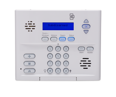
Interlogix
Simon XT
/XTi
Panel
2)
Alarm.com Z
-
Wave enabled
cellular
Module for Simon XT
/XTi
3)
Z
-
Wave peripherals to be installed (a list of tested and recommended
devices can be found at
www.alarm.com/empowerdevices
and some can
be ordered on the ADC dealer website)
Account Creation and System Setup
1)
Create a new account on the Alarm.com Dealer Website (or swap the
module into an existing customer account). Add the appropriate emPower
services (Lights, Thermostats, and/or Locks) on the
service plan page.
2)
Install the Alarm.com Z
-
Wave
-
enabled
cellular
Module in the XT
/XTi
, and
connect the panel’s battery and AC.
3)
Perform a
GSM/CDMA
test at the panel to initiate communication between
the module and Alarm.com.
Adding Z
-
Wave Devices
** Make sure the XT
/XTi
panel is connected to AC power
when enrolling Z
-
Wave devices.
**When
adding devices, first add the devices closest to the Alarm.com
system, and then move outwards.
**Devices must be
within 6 ft
of the Alarm.com module
when adding it to
the network.
Install each of the Z
-
Wave peripherals in their desired locations,
following the manufacturer’s instructio
ns.
Then follow the instructions below
to add (“include”) each de
vice into t
he Alarm.com module’s network.
If a
device will not be within 6ft of the Alarm.com
m
odule in its permanent
installation location, include it in the network
before
installation or use a
controller (controllers not available for locks, see below).
**If installing a portable Z
-
Wave controller (such as the
GE
45601), first add
the controller to the Alarm.com Z
-
Wave network using the Simon XT
/XTi
panel, and then use the portable controller to add the remaining devices to
the network while the devices
a
re in their permanent location.
(Locks cannot
be added to the
GE
45601, and will need to be
added by the Alarm.com
module.)
Devices must be within 6 ft of the controller if a controller is being
used to learn in devices.
**Run a Rediscovery from the pane
l or Dealer Site and verify that all added
devices are responding to commands.
Adding a Z
-
Wave device to the Alarm.com Module’s network
(“DEVICE INCLUSION”)
Checking the Device List with Alarm.com
Once you’ve added the devices, the customer website will automatically
update the Devices list (under the emPower
®
tab) within about 2 minutes of
the last device being added. You can also view the devices through the
Alarm.com Dealer Website by selecting the customer, clicking on the
“Equipment” link in the left
-
hand navigation, and then “emPower Devices” in
the top
navigation. You can perform a
cellular
phone test at the panel to
manually trigger the update.
Testing Device Communication with Alarm.com
Once the Z
-
Wave devices have been installed in their permanent locations
and are displayed in the
device list on Alarm.com, we recommend sending a
remote command to each device (e.g., turn on light; adjust target temp at
thermostat) in order to verify that it is successfully communicati
ng with the
Alarm.com module.
Deleting a Z
-
Wave Device (“Device Ex
clusion”)
You can delete a device from its current network whether it’s in the
Alarm.com module’s network or another network. On a Simon XT 1.2 (or
lower) follow the instructions for Adding a Z
-
Wave Device, except press and
hold “2” when in t
he Z
-
Wave Menu. On a Simon XT 1.3
,
follow the
instructions for Adding a Z
-
Wave Device, except scroll to “Delete Device”
after entering “Z
-
Wave Setup”.
On a Simon XTi, follow the instructions for
Adding a Z
-
Wave Device, except select “Remove Device”.
Once in Delete
mode, follow the manufacturer’s instructions for deleting the device. If a
device is no longer functioning, you can also delete it through the emPower
Devices page on the Alarm.com Dealer Website. Send a remote command to
the device and wa
it a few minutes for the command to register as failed.
Device
-
Specific
Instructions
Controllers
GE
Advanced Remote Controller (
GE
45601)
NOTE:
If a controller will be used with the system, Alarm.com recommends
adding it
before
the rest of the Z
-
Wave devices. Refer to the instructions
that came with your controller for more information on controller features
and operation.
Add Controller to Secu
rity Panel (System):
1)
E
nter your panel into Add Mode.
2)
With the controller close to your panel, press and hold the “SETUP” button
on the controller until the controller scre
en displays “LIGHT SETUP”.
3)
Use the arrow buttons to scroll until you see “TRANSFER” on the controller
screen. Press the “OK” button.
4)
The controller screen should now display “PRIMARY.” Use the arrow
buttons to scroll
until you see “RECEIVE”.
5)
Press the “OK” button. The controller
screen should display “RECEIVING”
.
6)
The controller screen will briefly display “SUCCESS” after the controller
has been successfully included into the panel.
Add Light Module to System using Controller
Note:
To add a light module using the controller
without
adding it a specific
number key on the controller, skip steps 4 & 5.
1)
Press and hold the “SETUP” button on the controller until the screen
displays “LIGHT SETUP”. Press the “OK” button.
2)
The controller screen should now display “AD
D”. Press the “O
K” button.
3)
The controller screen should
now display “TO NETWORK”.
4)
Use the arrow buttons to scroll until you see “TO A KEY” and
then press
the “OK” button.
5)
Press a number key 1
-
9 or “SETUP(Shift)” and a numb
er key for numbers
10
-
18.
6)
Press the “OK” button
and the screen should
now display “SETUP
WAITING”.
If the controller displays “Failure,” when adding a device, walk
towards panel and wait 2
-
5 minutes.
7)
Double
-
click
the button on the light module. The controller screen will
If Simon XT 1.2 or lower
-
Press & Hold * Key for
about 10 sec until LCD
displays “Z
-
Wave
Setup”.
-
Then press and hold 1
key until LCD displays
“Z
-
Wave ADD Mode”.
If Simon XT 1.3+ or
XTi
At keypad or touch
screen: System
Programming
(“Programming” for
XTi)
> Enter Installer
Code > Interactive
Services > Z
-
Wave
Setup > Add Device
Press
the appropriate button(s) on the Z
-
Wave device to add it to the
network.
See “Device
-
Specific Instructions” in this document (or the
instructions that came with the device) for more information.
Success!
Once a new device has been added successfully, the panel issues
a long beep, and the screen displays “Device
n
Added” (where
n
is the
device ID on the network). If the panel does not issue this confirmation,
try pressing the Z
-
Wave device’s button again,
or refer to “Device Not
Added Successfully” in the Troubleshooting section.
If Using Optional
Portable Z
-
Wave
Controller:
(first
add controller to
panel)
See instructions
on page 5 to
enter Add Mode
on the controller
Copyright © 2012
Alarm.com
|
www.alarm.com
|
v
2.5
2
emPower for Simon XT
/XTi
|
Installation Guide
briefly display “SUCCESS” and
the panel will beep to confirm you have
added the device to the controller key & system network.
8)
Wait until the
panel displays “Device Added”
to confirm that the device
info has been upl
oaded successfully to the panel. Walk towards the
panel until you do
not see the confirmation message within 10 seconds
Add Thermostat to System using Controller
1)
Press and hold the “SETUP” button on the controller until the screen
displays “LIGHT SETUP”.
2)
Use the arrow buttons to scroll until the screen displays
“THERMOSTAT”.
Press the “OK” button.
3)
The screen should now display “ADD”. Press the “OK” button. The screen
should
now display “SETUP WAITING”.
If the controller displays “Failure,”
when adding a device, walk towards panel and wait 2
-
5 minutes.
4)
Follow
the device
-
specific directions for the thermostat you are adding to
the system to trigger it. The controller screen will display “SUCCESS” and
the security panel will beep to confirm you have successfully added it to
the system network.
5)
Wait until the
p
anel displays “Device Added”
to confirm that the device
info has been upl
oaded successfully to the panel. Walk towards the
panel until you do not see the confirmation message within 10
seconds
Remove Light Module from System Network Using Controller
1)
P
ress
and hold the “SETUP” button on the controller until the screen
displays “LIGHT SETUP”. Press the “OK” button.
2)
The controller screen should now display “ADD”. Use the arrow buttons to
scroll until you see “DELETE”. Press the “OK” button.
3)
Double
-
click
the
button on the light module. The controller screen will
briefly display “SUCCESS” to confirm you have removed the device from
the controller key & system network.
Remove Thermostat from System Network Using Controller
1)
Press and hold “SETUP” until scr
een
displays “LIGHT SETUP”.
2)
Use the arrow buttons to scroll until the screen displays “THERMOST
AT”.
Press the “OK” button.
3)
The screen should now display “ADD”. Use the arrow buttons to scroll
until the screen displays “DELETE”. Press the “OK” button. The s
creen
should no
w display “SETUP WAITING”.
4)
Follow the device
-
specific directions for the thermostat you are removing
from the system to trigger it. The controller screen will display “SUCCESS”
to confirm you have successfully removed it from the system netw
ork.
Delete Controller from Security Panel (System):
1)
Enter your panel into Delete Mode.
2)
Follow steps 2
-
5 in the instructions for “Adding Controller to Security Panel”.
3)
The controller screen will briefly display “SUCCESS” after the controller has
been successfully deleted from the panel.
Lights & Appliances
Evolve Plug
-
in Lamp & Appliance or
Dimmer Module
1)
Plug in the device.
2)
Enter Add Mode on the security panel
.
3)
To add the device,
double click
the button in the middle of the light or
appliance module.
(Check instructions for the module if not evolve).
(If
there is no beep at the panel confirming successful
enrollment of the
device, try pressing the button again.)
Tips/Troubleshooting:
-
Lamp modules cannot be used with Compact Fluorescent Bulbs(CFBs).
Use appliance modules instead.
-
Make sure lamp to be controlled is plugged into the Z
-
Wave side of the
module (indicated by the Z
-
Wave logo).
-
We recommend u
sing a non
-
switched outlet for the module. If using an
outlet controlled by a switch, make sure the outlet is switched “On”
before sending light commands.
-
Keep lamps switched “On” to allow control thr
ough the Z
-
Wave module,
Alarm.com website and mobile applications.
-
Control dimming of lamp modules by pressing and holding button on the
module, or through the Alarm.com website.
Evolve Wall Mount Switch or
Dimmer
1)
Follow the provided directions to instal
l the device and ensure that it
functions proper
ly with manual on/off control.
2)
Enter Add Mode on the security panel
.
3)
To add the device,
double click
the
“evolve” side of the light switch
.
(Check instructions for the module if not evolve)
(If there is no beep at the
panel confirming successful enrollment of the device, try turning the
device on and off again.)
Tips/Troubleshooting:
-
Dimmer switches and On/Off switches cannot be interchanged. Use the
appropriate type of switch.
-
If it i
s
not practical to move the security panel 3
-
6 ft to the device,
consider investing in a
controller for installations.
Evolve Wall Mount Outlet
1)
Plug in the device.Follow the provided directions to install the device and
ensure that it functions
properly
with manual control.
2)
Enter Add Mode on the security panel
.
3)
To add the device,
double click
the button in the middle of the outlet.
(Check instructions for the module if not evolve)
(If there is no beep at
the panel confirming successful enrollment of the device, try double
-
clicking the button again.)
Tips/Troubleshooting:
-
If it is
not practical to move the security panel 3
-
6 ft to the device,
consider investing in a controller fo
r installations.
-
We recommend using a non
-
switched outlet for the Z
-
Wave outlet. If
using switch outlet, make sure the outlet is switched “On” before sending
commands.
-
Only the lower outlet is controlled by Z
-
Wave. Ensure you’re plugging
devices into
the lower outlet while testing if the outlet works for Z
-
Wave
control. The opposite is true if the device is installed upside down.
Locks
IMPORTANT NOTE
: If the security panel cannot be taken to within 6 feet of
the lock installation location or vice versa, add the lock to the system
before
you install the lock on the door
. (You will need to connect the battery pack
to the keypad before attempting to per
form these steps.)
NOTE:
Locks cannot be enrolled using a portable controller. Locks must be
enrolled directly through the panel.
Tips:
-
Before removing old locks or beginning installation, check the layout of door
to make sure the new lock will not conf
lict with existing hardware.
-
Contact a locksmith if you experience difficulties removing old hardware or
installing the new lock.
-
Send user codes to the lock (via the customer website)
before
leaving the
property. Alarm.com does NOT recommend programmi
ng codes locally via
the lock keypad
—
all codes should be programmed through the Alarm.com
interface.
Kwikset Deadbolt
1)
Follow the instructions included with the lock to put the lock together but
do not install it on the door yet
2)
With the lock within 6
ft of the panel, enter the panel into
Add Mode.
3)
To trigger the lock to add it,
press button “B” (shown below).
Important:
Do not touch the lock or the panel for one full minute. Failure
to do so will result in lock malfunctions.
Copyright © 2012
Alarm.com
|
www.alarm.com
|
v
2.5
3
emPower for Simon XT
/XTi
|
Installation Guide
4)
Move the lock to it
s final location (with repeaters included along the way
if lock is not within direct range of the panel). Send commands to the lock
and ensure it is successfully learned into the network and then finish
ins
talling the lock on the door.
5)
Login online to the
customer account at www.alarm.com to select which
user codes
are allowed to use this lock.
To do this, go to the “emPower”
then “Locks” ta
b.
On the User Codes table, you will see a
column labeled
“Lock Access.”
Check the box of the lock you want to allow each user code
to access.
Yale Touchscreen and Keypad Deadbolts
1)
Follow the instructions included with the l
ock to put the lock together,
do
not install it on the door yet.
Insert batteries and change the maste
r
code.
2)
With the lock within 6 ft of the panel, enter panel into
Add Mode.
3)
Trigger the lock by entering the master code #, 7 #, 1 #.
Important:
Do not touch the lock or the panel for one full minute. Failure
to do so will result in lock malf
unctions.
4)
Mov
e the lock to its final location (with repeaters included along the way
if lock is not within direct range of the panel). Send commands to the lock
and ensure it is successfully learned into the network and then finish
installing the lock on the door.
I
mportant:
The lock is currently handed to the right. If the door requires
the lock to be handed to the left, then you will need to reset the lock
while the lock is on the door.
Resetting the lock allows the lock to hand
itself and returns the lock to p
rogramming default
–
deleting all user
codes and setting the Master PIN code back to default (12345678), but it
does not remove the
lock from the Z
-
Wave network.
5)
Login online to the customer account at www.alarm.com to select which
user codes are allowed t
o use this lock. To do this, go to the “emPower”
then “Locks” tab. On the User Codes table, you will see a column labeled
“Lock Access.” Check the box of the lock you want to allow each user
code to access.
-
Note: By default auto
-
relock is turned on.
To turn off this setting for the
touchscreen: master code #, 3 #, 3 #. To turn off this setting for the
keypad: master code #, 4 #, 3 #.
Schlage Lever Lock or Schlage Deadbolt
Note:
Ask your customer to save the programming code that comes with the
lock. This will be convenient to have if they ever have issues in the future.
1)
Follow the instructions included with the lock to put the lock together but
do not install it on the door ye
t.
2)
With the lock within 6 ft of the panel, enter the panel into
Add Mode.
3)
O
n the lock keypad, enter the six
-
digit programming code (given by
Schlage), then press the “Schlage” button, followed by “0”. The Schlage
button will flash orange
while it is commu
nicating with the panel. Once
the lock has been added successfully, the Schlage button will flash green.
Important:
Do not touch the lock or the panel for one full minute. Failure
to do so w
ill result in lock malfunctions.
4)
Move the lock to its final lo
cation (with repeaters included along the way
if lock is not within direct range of the panel). Send commands to the lock
and ensure it is successfully learned into the network and then finish
installing the lock on the door
.
5)
Login online to the customer
account at www.alarm.com to select which
user codes are allowed to use this lock. To do this, go to the “emPower”
then “Locks” tab. On the User Codes table, you will see a column labeled
“Lock Access.” Check the box of the lock you want to allow each us
er
code to access.
Thermostat
s
Tips:
-
The new thermostat should be placed in the same location as the original
thermostat unless an HVAC professional approves a new location.
-
Learn the thermostat into your emPower network while it is powered using
the power
-
source (AC
-
power vs. battery
-
power) it will use during regular use
after the installation.
-
The Trane Thermostat requires a 24 VAC common wire to power the
thermostat and
we strongly recommend AC power for the
GE
Basic
thermostat with battery power backup. Before beginning installation, verify
the HVAC system has a common wire or contact a qualified HVAC technician.
If the security panel cannot be taken to within 6 feet
of the thermostat
installation location and you do not have a portable controller, power the
thermostat temporarily using a 24 volt transformer and add the thermostat
to the system
before
installing the thermostat.
CT
-
30 and CT
-
100 Z
-
Wave thermostats
1)
Follow the manufacturer’s instructions to install the thermostat.
2)
Enter Add Mode on your panel.
3)
Enter the Menu Screen b
y
hitting MENU. Touch the Mate/Link button
(looks like a tower) o
n the left side of the screen.
Trane Remote Energy Management
Thermostat
1)
F
ollow the manufacturer’s instructions
to install the thermostat.
2)
Enter Add Mode on your panel.
3)
Hit the “MENU” button on the thermostat panel. Scroll down to “Z
-
Wave
Install” and press “Select”. Press the “Yes” button to enroll thermostat.
\
E
nergy Monitoring
Aeon
Labs Home Energy Meter G1:
1)
Follow the instructions for Aeon Labs HEM to install the hardware inside a
circuit breaker.
2)
Enter the panel into Add Mode
3)
Press the Action Button.
4)
If your meter has been successfully linked to your network, its light will
remain solid for 3 seconds. If the linking was unsuccessful the light will blink
after pressing your meter’s Action Button.
Jasco
Energy Monitoring Appliance Module:
1)
Plug in the module.
2)
Enter Add Mode in the security panel.
3)
To add the device, click the button in the middle of the appliance module. (If
there is no beep at the panel confirming successful enrollment of the device,
try
pressing the button again.)
Aeon Labs Smart Energy Switch G1:
1)
Plug in the module.
2)
Enter Add Mode in the security panel.
3)
To add the device, click the button surrounded by blue LED.
4)
The LED will be solid or off if the SES has been successfully included
into a
network.
Troubleshooting
The device will not learn into the system
If there is an error, or the two minute time limit expires when adding a device,
try the following troubleshooting steps:
a.
Make sure the panel is connected to AC power while you’re adding,
deleting, or operating Z
-
Wave devices.
b.
The device may already be part of a Z
-
Wave network (even if it is a
brand new device). Try deleting (“excluding”) it from its network and
then try a
dding it again. You should always be able to either add or
delete the device from the network. If you receive a Timeout/Error
message when trying to delete the device, it’s likely the issue is range
-
related (see d and e below).
c.
You may need to move the
device closer to the panel (or vice versa)
Copyright © 2012
Alarm.com
|
www.alarm.com
|
v
2.5
4
emPower for Simon XT
/XTi
|
Installation Guide
while adding it, or use a portable controller to add it. We recommend
that devices are within 6 feet of the panel or controller, but the closer
the better.
d.
Check to see if there are other 900 MHz wireless devi
ces that could be
interfering with the Z
-
Wave messages. Try moving or replacing any 900
MHz headsets, cordless phones, baby monitors, wireless speaker
extenders, IR remote control extenders, or similar devices. Or, try
changing the channel used by these
devices.
e.
Try moving the position of the panel relative to the device and/or
changing the orientation of the device. Some Z
-
wave devices have
directional Z
-
wave signals. (e.g. Some devices the Z
-
wave signal may be
stronger to the front compared to behind t
he device).
The device works close to the panel, but does not work in its final location
In this case, you likely have a range issue. Try adding repeaters to expand and
strengthen your Z
-
Wave network. Here are some tips to help your network:
a.
Expand your
network using repeaters in pairs
.
If a device has been
added successfully but does not appear to be communicating reliably
with the system, it may be necessary to place another Z
-
Wave device
(that’s already on the network) between the panel and the proble
m
device, to serve as a repeater that can relay messages between the
two. Expanding in pairs allows for multiple Z
-
Wave communication
paths, preventing any one device from becoming a “bottleneck” in the
network.
b.
Expand Your Network Using “Beaming” Devic
es
. Locks and battery
-
powered thermostats enter sleep mode to conserve battery
-
life, and
therefore can only communicate directly with the panel or with
“beaming” devices that can send wake
-
up messages. In general,
devices powered off of batteries do NOT
beam, and most (but NOT all)
AC
-
powered devices beam.
Note
: Newer
GE
/Jasco light/appliance modules support beaming, but
some earlier versions did not. To find out if a given
GE
module is
beaming
-
compatible, check the label. The
GE
light/appliance plug
-
in
module supports beaming if the date code starts with 11 OR the version
includes the letter a or the letter b.
c.
Check to see if there are other 900 MHz wirele
ss devices that could be
interfering with the Z
-
Wave messages. Try moving or replacing any 900
MHz headsets, cordless phones, baby monitors, wireless speaker
extenders, IR remote control extenders, or similar devices. Or, try
changing the channel used by
these devices.
d.
Try moving the position of the panel relative to the device and/or
changing the orientation of the device. Some Z
-
wave devices have
directional Z
-
wave signals. (e.g. Some devices the Z
-
wave signal may be
stronger to the front compared to b
ehind the device).
I don’t want the thermostat to be solely battery powered, but a “C” wire
does not exist from the HVAC unit.
It is possible to link a transformer to the thermostat as a substitute “C
-
wire”,
however every thermostat is different. Please
make sure to check the
thermostat manual for the correct terminals to attach the transformer wires.
Please also check thermostats for power requirements (some thermostats
are more sensitive than others to input current).
The lock is not securely enrolled
Lock devices must complete a “secure enrollment” process during addition,
which can take up to a minute to complete while the lock is
within 6 feet
from the panel.
If this process is interrupted before completing, the lock will
not function properly. A w
arning message will display on the Alarm.com
customer site and on the Dealer Site that secure enrollment is not complete.
The lock should be deleted from the network and re
-
added, then do not
touch the panel or the lock for one full minute.
The lock is
not reporting back the correct status
There are a few reasons this could be happening. Try the following
troubleshooting steps:
a.
First, check to make sure you’re using high quality, name brand
batteries, such as Energizer or Duracell. Generic batteries of
ten
do not read back the proper status because they use up all of their
power locking/unlocking the lock.
b.
If the lock is a deadbolt, check to make sure that there i
s
enough
room in the wall for the bolt to fully extend. Depending on the
lock, you might
be able to change the settings for how far the bolt
extends. Check your lock’s installation guide to see if this setting is
available.
c.
If neither of the steps above help, then you likely have a range
issue. Consider adding more devices to act as repeat
ers and/or
look at the rediscovery option available for your panel below.
Devices are malfunctioning, but range is not the issue
a.
For networks with more than one device, send a rediscover
network command. After all devices are learned in, have power,
a
nd are in their final locations, try sending a Rediscover Network
command from the Dealer Website (or from the panel if you are
using an XTi panel). This will update the routing table for each
device, making it so that the devices communicate in an effici
ent
path. Newer firmware versions support this command and have it
available under the emPower Devices section of the Equipment
page. If you do not have a Rediscover Network button available
on the emPower Devices page, we may be able to upgrade your
fir
mware remotely so that it becomes available for your module.
b.
Try rotating the orange antenna on the module. Moving the
orange antenna so that it points down could help if it is
experiencing interference in its current position.
Z
-
Wave Setup Menu Not Available / “Z
-
Wave Radio Not Found” Message
If the Alarm.com module is Z
-
Wave
-
enabled and
you’re using a rev3
(module with firmware version
144
-
149)
board, but the Z
-
Wave board is not
recognized, make sure that the Z
-
Wave Board is
securely connected to the Alarm.com GSM module.
Try pressing it into the GSM module to make sure it
is securely connected. Then power cycle the system
and check to see if t
he Z
-
Wave menu is available.
No Home ID
This error occurs when the Alarm.com module has not
received the Z
-
Wave “Home ID”. Usually, this occurs
when the module has not yet communicated with
Alarm.com since the Home ID is sent during initial
communica
tion. Perform the cellular
phone test and confirm that
communication between Alarm.com and the module has been initiated. If the
module is already communicating with Alarm.com and this error persists, check
that the Z
-
Wave daughterboard is securely conne
cted to the module and power
cycle the unit.
Device Already in Network
The device being added is already part of a Z
-
Wave network (whether the
existing network or an old network) and cannot be added again. Clear the
device by deleting (“excluding”) it from its network. You should always be able
to either delete or add a dev
ice to a network. Note: The Alarm.com module
can be used to delete devices in any network. The device will clear itself and be
able to be added to another network. The device’s old network will still list that
device as part of its network (but the dev
ice will not be able to be controlled by
that network) until the device is remove from its old network.
UTC panels
-
Z
-
Wave LED Status/Troubleshooting Lights
Modules with firmware 144
-
149 (Rev 3)
SIM Card
Z
-
w
ave
Board
Copyright © 2012
Alarm.com
|
www.alarm.com
|
v
2.5
5
emPower for Simon XT
/XTi
|
Installation Guide
Z
-
Wave LED Status Indicators
Error
Light
Busy
Light
Devi
ce Status or Error
Duration of LED Pattern
4
-
blink
Add mode
As long as module is in
Add mode (max 120
seconds)
2
-
blink
Delete mode
As long as module is in
Delete mode (max 120
seconds)
Normal mode
N/A (this is the light’s
default state)
Solid
Successful add
node/remove node/
replication
60 seconds
5
-
blink
No home ID assigned to
Alarm.com module
Until a GSM phone test is
performed
4
-
blink
Error with Add
node/Delete node/
Replication
60 seconds
4
-
blink
Steady
blinking
Add node attempt failed
because node already in
network
60 seconds
3
-
blink
One or more nodes did
not respond (may be
unplugged or out of
range)
60 seconds
2
-
blink
An ack is not received
from another node (rare)
60 seconds
1
-
blink
No other nodes are in the
network
Until a
node is added to
the network
Solid
Solid
Unit was just powered on
3 seconds after unit is
powered on
GSM modules with firmware 150 + or CDMA modules with firmware 170+
(Rev 4 modules)
Z
-
Wave LED Status Indicators
LED 2
LED 5
Device Status or Error
Description
4
-
blink
Add mode (lasts 120
seconds or until a device
is added)
In this mode you can add
a device to the local Z
-
Wave network. Devices
cannot be added to a
network if they are
already a part of a
network
2
-
blink
Delete mode (lasts 120
seconds or until a device
is added)
In this mode you can
delete a device from a Z
-
Wave network. A device
can only be in one
network at a time, and
must receive a “delete”
command before it can
be learned into a new
network
Solid
Successful add
node/remov
e
node/replication (lasts 60
seconds)
After receiving this signal
leave all devices by the
GSM Module for 1
minute. Locks must be
left next to the Module
for 4 minutes
Solid
with
one
blink
Add node attempt failed
because node already in
network (lasts 60
seconds)
Device you attempted to
add to a network is
already in a network, and
must be “deleted” before
it can join a new network
2
-
blink
No other nodes are in the
network (lasts until a
device is added to the
network)
No devices have been
added that
can be
controlled by the GSM
Module yet. See above
for instructions on how to
add devices
5
-
blink
Learn mode error (lasts
60 seconds)
The device you
attempted to add into a
Z
-
Wave network was not
successfully added
6
-
blink
No Home ID present
(lasts
until the module
connects to Alarm.com
and is configured)
When the GSM Module
first connects to
Alarm.com it is
configured with a
necessary unique
network ID
- Uploaded