Interlogix Simon XTi-5i - User Guide Dated 10/16/18
Related Products

Related Categories
- Wireless Touchscreen Alarm Panels
- Small Business Security Systems
- Monitored Home Security Systems
- DIY Wireless Security Systems
- Apartment Security Systems
Document Transcript
©
07/05/18
UTC Fire & Security. All rights reserved.
1
/
10
P/N
46
6
-
5437
•
REV
A
•
1
6
OCT
1
8
Simon
®
XTi
-
5
Version 2
User Guide
Introduction
This is the
User
Guide for the Simon
®
XTi
-
5
Version 2
system (models 600
-
1054
-
95R
-
18
& 600
-
1054
-
95R
-
18
-
CN).
The Simon
®
XTi
-
5
(V2)
provides a graphical user interface
for programming and system op
eration. A piezo siren is
provided for alarm and status annunciation. A speaker and
microphone is provided for 2
-
way voice communication with
the central station
.
Safety Information
WARNING
:
CHOKING HAZARD.
The product accessory bag
contains items that
could be choking hazards. Please
keep away from small children.
AVERTISSEMENT:
Le sachet de produits accessoires contient des
éléments qui pourrait présenter un danger d’étouffement. Veuillez
garder hors de la portée des jeunes enfants
.
Operation
Use this document to quickly begin operating your Simon
®
XTi
-
5
(V
2
)
security
systems
. Refer to
the Simon
®
XTi
-
5 User
Manual
Version 2
for full operating details and programming
options. To download the Simon
®
XTi
-
5 User Manual
Version 2
see “Contact information” on page
10
.
Note:
The default master code is 1
-
2
-
3
-
4 when
the security system
is shipped from the factory. You should change your code
after your system is installed (see “Programming” on
page 6).
To operate the security system:
Use the
Main
screen icons to arm/disarm the system
when you enter or exit your
home and to determine
which sensors are active and the system status.
Use the emergency screen to communicate with the
central monitoring station to report police, fire, or
emergency alarms.
From the
Main
screen, press the Status & Settings
icon to program certain user features. Refer to the
Simon
®
XTi
-
5 User Manual
Version 2
for more
information.
Note:
Upon initial installation, it may take up to 36 hours for the
battery to fully charge
.
A low battery icon will be present and
trouble beeps will sound until the battery is sufficiently
charged. After the initial charge, should the panel lose AC
Power and experience a low battery condition, the icon will
appear and trouble beeps will sound unless silenced.
S
ilence trouble beeps by:
Arming or disarming the system.
or
Pressing
“
STATUS & SETTINGS
”
icon and pressing
“
LISTEN
”
next to Panel Status.
This will disable the sounder for 4 hours but the
trouble
indication will remain until the battery is recharged.
Contact your
security provider
to replace your backup
battery.
This system is intended to be checked by a qualified
technician at least once every 3 years.
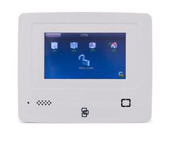
Main
Screen
Figure 1:
Main
Screen
The look and color of the
Main
Screen may vary depending up on
the configuration by your security provider.
The location of the
buttons, controls, and icons are the same as shown in this man
ual.
C
olors and icon styles may differ to match those of the service
provider's mobile application.
For any questions contact your
security provider.
2
/
10
P/N
46
6
-
5437
•
REV
A
•
1
6
OCT
1
8
There are several ways to navigate to the
Main
screen
(T
able 1
describes its features):
By pressing the
Close
icon.
Depending on the
current screen, the user may
need to press the
C
lose
icon multiple times
.
After a period of inactivity, the
Main
screen will return
(unless you set a blank screen as your default screen
saver).
If an alarm occurs, the screen will automatically return to
the
M
ain
screen.
Note:
The touch screen will automatically blank at 2:00 am daily for
60 minutes. Touch the screen to reactivate.
Note:
The
Main
screen factory default can be changed the
after
your security provider’s
installation has been completed.
Table 1:
M
ain
Screen
Icon
Description
Access the emergency screen to sele
ct the
appropriate emergency icon (Panic, Police, or
Fire).
The current system time.
Depicts the status of the AC power and battery.
Note
: These icons only appear in red on the
main
screen if the backup battery is not fully
charged or AC power is not working correctly.
This yellow triangle indicates faults within the
system.
This will appear on the
Main
scr
een in the event
of an alarm. Messages will also display on this
icon describing what caused the alarm. Press
this icon to cancel the alarm.
*
Depicts monitored door status. A green check
indicates all monitored doors are closed. A red
exclamatio
n point indicates one or more doors
are open.
*
Depicts monitored window status. A green
check indicates all monitored windows are
closed. A red exclamation point indicates one
or more windows are open.
*
Depicts motions sensor status.
A green check
indicates no recent motion detected. A red
exclamation point indicates motion was
detected in the last 10 minutes.
*
Depicts other changes to protected property in
your system. A green check indicates all
sensors are closed and no
activity since you
last checked. A red exclamation point indicates
either a sensor is tripped, or there is
unacknowledged activity.
*
Note:
Pressing the above sensor icons will open a new screen to
provide more detail. These icons may contain the text “N
/A”
which indicates your system is not configured to support
this feature. Consult your dealer for additional information.
Icon
Description
Press this icon to access the Arming Screen.
One of these icons will display depending on
your arming level. Pre
ss to turn off
intrusion/burglary protection for your system.
Only intrusion/burglary sensors are disarmed.
Environmental sensors, such as smoke and
carbon monoxide detectors, stay active at all
times
.
Enter your code in the keypad screen that
appears. If
you enter an incorrect code, press
the Clear icon and enter the correct code.
Press to access the Status & Settings screen.
Arming Screen
When you touch the PRESS TO ARM icon on the
Main
screen, the Arm screen appears with the following arming
choices:
Figure 2:
Armin
g Screen
Note:
Depending on configuration by your security provider
, your
ARM screen may have three buttons displayed instead of
two.
Table 2:
Arming Screen Icons
Icon
Description
AR
M
STAY
(Doors
and
Windows Only
)
This
icon
activates perimeter sensor only.
ARM
AWAY
(ALL)
This
icon
activates all sensors.
MORE
This
icon
opens
optional arming choices
“
Silent Exit
”
and “Entry Delay”
.
Note:
You will see icons at the top of
the screen depicting the
current state of your installed sensors.
P/N
46
6
-
5437
•
REV
A
•
1
6
OCT
1
8
3
/
10
Optional Arming Choices
These settings are optional (for more advanced arming
features).
Silent
E
xit
:
Press this icon to silence your exit beeps
during arming. (Your exit time will dou
ble).
Entry
D
elay
:
Press this icon to set your entrance timer
to zero. (Use the
“
No Delay
”
feature when you are
asleep, or when you are away from home and will carry
a wireless touchpad that allows you to disarm the
system before opening a protected do
or). If you select
the No Delay option, (clock with a red strike
through) will appear over the lock when the system is
armed.
Arming errors
If an option
is selected
on the Arm screen and there is a
problem, an arming error message will appear, ind
icating the
nature of the problem and how to resolve it.
For example,
you mig
ht see a message that indicates that you need to
close the front door.
Correct the problem as indicated or press Bypass.
The user
will
then
see
an
arming countdown message at the bottom of
the screen.
T
ouch
the
Cancel
icon
and enter
a v
alid
code to
stop the arming process.
Status and Settings Screen
To access the Status & Settings screen, press
on the
Main
Screen. Refer to Table 3 below for more information on
Status & Settings screen options.
A gold icon indicates an option is
selected.
A blue icon indicates an option is not selected.
Table 3:
Status and
Settings
S
creen
O
ptions
Item
Description
AC Power
(battery)
Depicts the status of the AC power and backup
battery. A red power cord represents loss of
AC power to the system. A green
power cord
icon represents AC power to the system. A red
battery icon represents a low battery charge. A
green battery icon represents a fully charged
battery.
Note
:
These icons only appear on the main
screen if the backup battery is not fully
charged o
r AC power is not working
correctly. It is recommended that
the
backup battery be replaced every 3
-
5
years. Contact your
security provider
to
replace the backup battery.
Event History
Press the Show icon to view system events
.
Note
:
If a # appears
in the Event History list,
the event was not sent to the central
station.
Item
Description
Direct Bypass
Press the Select icon to enter the sensor
bypass screen. Sensor can only be bypassed
if actively armed.
Panel Status
Press the Listen icon to listen to the status of
your security system. Press Clear to clear the
status.
Chime
Press the On/Off icon to set the chime feature
On/Off.
Note
:
This option may or may not appear
depending on panel programming.
Special Chime
Press the On/Off icon to set the special chime
f
eature On/Off.
Note
:
This option may or may not appear
depending on panel programming.
Lights
Optional. Ask your dealer for more
information.
Note
:
Has not been investigated by UL.
Door Locks
Optional. Ask your dealer for more
information.
Note
:
Has not been investigated by UL.
Garage
Door
Optional. Ask your dealer for more
information.
Note
:
Has not been investigated by UL.
Voice Volume
Press the arrows to adjust the speech volume
level.
Beep Volume
Press the arrows to adjust the beep volu
me
level.
Brightness
Press the arrows to adjust the screen’s
brightness.
Default screen
Use this feature to set this panel’s screen
saver mode. Select “Blank”
icon
to have the
screen go dark after a period of inactivity.
Otherwise, the default will be th
e
Main
screen
and the screen will be lit. If AC power is lost,
the screen will go blank after 2 minutes of
inactivity to maximize battery life. The green
AC power icon will blink.
Note
:
The screen will automatically go blank
at 2:00 am daily for 60
minutes.
Calibration
Press the Show icon to enter the calibration
screen. This screen will allow you to
recalibrate the touch screen.
Help
Press the Help icon to access the Help menu.
Set Date/Time
Press
ENTER
next to Set Date/Time to set the
date and
time. (A valid master code is
required.)
System Tests
Press
ENTER
next to System Tests to access
Sensor Test, Comm Test, and System
Download options. (A valid master code is
required.)
Programming
Press
ENTER
next to Programming to access
the programmin
g menu. (A valid master code
is required.)
Version
Displays the system’s firmware version, touch
screen version and copyright information.
4
/
10
P/N
46
6
-
5437
•
REV
A
•
1
6
OCT
1
8
To set the time:
1.
From the Status & Settings screen, select Set
Date/Time.
2.
Enter access code.
3.
From the Set Date/Ti
me screen press the first box to set
hour and press
the
SAVE
icon
.
4.
Press the second box to set minutes and press
the
SAVE
icon
.
5.
Press a.m / p.m. box to toggle a.m / p.m. setting.
To set the date:
1.
From the Set Date/Time screen press the first box in
the
second row to set the month and press
the
SAVE
icon
.
2.
Press the second box to set the day and press
the
SAVE
icon
.
3.
Press the third box and enter the year and press
the
SAVE
icon
.
4.
Press
the
CLOSE
icon
repeatedly to exit.
Emergency I
con
In an em
ergency, touch the Emergency icon. An Emergency
screen appears (see Emergency icon in Table 1 on page 1).
You will see three icons (Panic, Police, or Fire). Select the
appropriate icon.
Note:
If your system is connected to a security monitoring service,
t
he authorities will be notified. This option may not be
enabled. Contact your dealer for details.
If you initiate an emergency alarm by mistake, you can
cancel the alarm by touching the red Alarm icon and entering
your code within 30 seconds (typical tim
e limit, contact your
dealer for more information on your system configuration).
Fire A
larm
V
erification
If this option is off, the panel immediately reports to the
central station when a smoke detector goes into alarm.
With this option on, if a single smo
ke detector goes into
alarm, the panel will not report for 60 seconds unless
another smoke detector goes into alarm. If the first smoke
detector is cleared of an alarm within the first 60 seconds, no
report will be sent to the central station unless it or
a second
smoke detector goes into alarm within the panel siren
timeout period (5 minutes).
Ask your
security provider
how this option is programmed.
Arming and
D
isarming
Use the steps below to arm and disarm your system:
To disarm:
1.
Press
“
PRESS TO DISAR
M
”
.
2.
Enter your code when the keypad screen appears. If
you enter an incorrect code, press the Clear icon and
enter the correct code.
Note:
You have four seconds between number presses to enter
the code or you will be returned to the
Main
screen.
To
arm STAY or AWAY (if two buttons are shown) or
STAY, AWAY, Motions Sensors Only (if three buttons
are shown):
1.
Press
“
PRESS TO ARM
”
icon
.
2.
Press
“STAY or AWAY
, MOTION SENSORS ONLY, or
ARM ALL
”
.
3.
If a code is required, enter your code when the keypad
screen appears.
The panel starts an exit delay and sounds exit beeps until
the exit delay expires (see Table 4 on page 5).
Unvacated Premises
Unvacated Premises is a feature that determines whether
th
e system automatically arms down to level 2 (
STAY
-
doors and windows) if arming the system to level 4 (
AWAY
-
doors, windows, and motion sensors) without opening or
closing a perimeter door (on), or remains at the armed level
chosen (off). This feature do
es not work from a key fob.
Auto
bypass
must be on for this feature to work. Check with your
security provider
to see how these options are programmed
for your system.
Swinger Shutdown
This setting determines if a sensor or zone will go into alarm
only onc
e during an arming period (an active arming level)
and will not be active again until the alarm is canceled
(Swinger Shutdown is enabled) or the sensor or zone will
always be active and will go into alarm multiple times during
an arming period (an active a
rming level) without canceling
the alarm (Swinger Shutdown is disabled).
Note:
Swinger Shutdown does not affect Smoke, Fire, Carbon
Monoxide and Environmental sensors.
Ask your
security provider
how this option is programmed
and have them explain how it w
ill affect your system
operation.
P/N
46
6
-
5437
•
REV
A
•
1
6
OCT
1
8
5
/
10
Exit/entry Delay
Your Simon
®
XTi
-
5
(V2)
provides a delay after entering or
exiting your home before the system is armed or disarmed.
Exit Delay Extension
If enabled by your
security provider
, the exit delay extension
feat
ure will recognize when arming the system, leave your
house and then quickly reenter (for example, if you forget
your car keys). If this happens, the system will restart your
exit delay to give you the full exit delay again.
Ask your
security provider
how
this option is programmed.
Alarms
The system provides annunciation to indicate an alarm
condition. When an alarm is active, the
Main
screen will
display the alarm status (see Table 1 on page 1).
To cancel the alarm:
If you would like to hear additiona
l alarm information,
press Listen.
To cancel the alarm, press the red alarm icon and enter
a valid master or user code.
After alarms are canceled, the system will be disarmed.
System status
In the Status & Settings screen, press Listen (no code is
require
d) to cause the system to speak the following types of
information:
Alarm conditions
Alarm history
Trouble conditions
Open sensors
Bypassed sensors
RF Interference trouble
The
and
icons appear when abnormal
conditions such as a trouble or open senso
r exists in the
system.
You can clear certain status entries from the system (such
as old alarm history) by listening to the message or by
pressing
the
Clear
icon
next to Panel Status in the Status &
Settings screen.
Remote TouchScreen,
Touchpads and
Key
f
obs
T
ouchScreen,
touchpads and key
fobs
can be used
to control
the security system from remote locations in and near your
home. Interfacing with the system using a
T
ouch
Screen
or
touchpad
is similar to using the panel.
Status Beeps
The pa
nel sounds status beeps to alert you to various
system events and conditions as shown in Table 4 below.
Table 4:
Status Beeps
Activity
Beep response
STAY
(
d
oors
and
w
indows
)
Exit delay and entry delay beeps sound two times
every 5 seconds and two times per second
during
the last 10 seconds.
AWAY (d
oors
,
w
indows and
m
otions
)
Exit delay and entry delay beeps sound
three
times
every 5 seconds and
three
times per second during
the last 10 seconds.
Motions
(shown
if three button
arming is
en
abled)
Exit delay and entry delay beeps sound
four
times
every 5 seconds and
four
times per second during
the last 10 seconds.
Disarm
One beep.
Chime
Two beeps.
Special chime
Three beeps.
Property/asset
management
One beep. (Information displays only o
n the Two
-
Way Talking Touch Screen).
Trouble beeps
Six beeps every minute. Press Listen next to Panel
Status to stop beeps for 4 hours.
No activity
beeps
Twenty beeps every minute for 5 minutes (feature
must be programmed by the
security provider
).
Ala
rm Sirens
Exterior and interior sirens make three different alarm
sounds on the premises, each indicating a different type of
alarm. Sirens are programmed by the
security provider
to
time out and stop sounding after a specified time.
Table 5
desc
ribes the siren sounds used by the security
system.
Table 5:
Siren Sounds
Function
Fire
CO
Intrusion
Emergency
Interior and
panel siren
Temporal 3
Temporal 4
Steady
Fast on/off
Exterior siren
Temporal 3
Temporal 4
Steady
Note:
Temporal 3
or 4
refers to a contin
uous pattern of three siren
pulses, then off for 1.5 seconds, three siren pulses, then off
for 1.5 seconds.
Trouble Beeps
Your security system is able to automatically test itself for:
Power failures
Low batteries
Sensor supervision
Communication trouble w
ith modem hardware installed
in the panel or communication
trouble
with central
monitor station
6
/
10
P/N
46
6
-
5437
•
REV
A
•
1
6
OCT
1
8
When your system detects one of the problems above, six
rapid beeps sound every minute until the troubl
e condition is
corrected
(depends on the security
provider’s
configuration)
.
To stop the trouble beeps, enter the Status & Settings
screen and press
“
Listen
”
. Trouble beeps will resume 4
hours later unless the trouble condition is corrected.
Note
:
Trouble
Beeps can be configured to not occur during 8PM
-
8AM or to only occur during that time if a communication
trouble occurs none other.
It is therefore possible your
system may not trouble during those hours.
Programming
Your Simon
®
XTi
-
5
(
V2
)
security syste
m allows you to
program certain user options, such as access codes.
To enter programming mode:
1.
From the Status & Settings screen, scroll down to the
Programming option and press
“
Enter
”
.
2.
Enter the access code and press
“
OK
”
.
Access codes
To add/edit
access codes:
1.
From the Programming screen, press
“
ACCESS
CODES
”
.
2.
To add or edit an access code, press the white field next
to the access code.
3.
Enter the new/edited code on the numbered keypad and
press
“
SAVE
”
.
4.
Press
the
CLOSE
icon
repeatedly to
exit menus.
Chimes
Use the chime feature to signal when a protected door is
opened while the system is disarmed. The panel chimes
when a chime sensor is tripped, if the chime mode is
enabled. This feature allows you to be notified when family
members are
going in and out of your home. The chime
feature is turned on or off in the Status & Settings screen.
Note:
If there are no chime sensors in your system, you will not be
able to enable the chime feature.
Your
security provider
may have programmed the syste
m to
speak the sensor name or make a custom chime sound
when a chime sensor is tripped. The chime sound, if
programmed, will be played in place of the standard chime
beeps.
To enable or disable the chime feature:
1.
Open the Status & Settings screen. The
gold icon
indicates an option is selected.
2.
To change the value, press
ON
or O
FF
icons
next to
Chime (depending on the settings your
security provider
has
programmed, it may not be possible to turn on the
feature).
3.
Press
the
Close
icon
to exit.
Specia
l Chime
The special chime feature allows you to install motion
sensors in a patio or at the front door, and be notified when
someone is approaching those areas. These motion sensors
are not used for intrusion protection. The panel will chime, if
the specia
l chime mode is enabled.
Note:
If there are no sp
ecial chime sensors in your system, the
special chime option will not appear in the
Status & Settings
screen.
To enable or disable the special chime feature:
1.
Open the Status & Settings screen. Scroll dow
n until
you find the Special Chime feature. The gold icon
indicates an option is selected.
2.
To change the value, press O
N
or O
FF
icons
next to
Special Chime.
3.
Press
the
Status
icon
to exit.
Cross
-
zoning
Cross zoning (two
-
trip) refers to two different m
otion sensors
that must be tripped within two minutes of each other to
report an alarm to the central station. The Cross
-
zoning
figure shows the path of a person walking from the kitchen to
the living room. When the person is detected walking
through the
k
itchen, the motion sensor in the kitchen is
tripped, sounding a local alarm. If motion is detected by the
living room motion sensor within two minutes, an alarm
report will be sent to the central station.
Figure 3:
Cross
-
zone
D
iagram
P/N
46
6
-
5437
•
REV
A
•
1
6
OCT
1
8
7
/
10
System Tests
Sensor Test
S
ensors
should be tested
one at a time to make sure they
are sending strong signals to the panel.
Users
should test
the sensors at least once a week.
To perform the sensor test:
1.
Enter the Status & Settings menu.
2.
Scroll until System Tes
ts is listed, Press
“
Enter
”
.
3.
Enter
master code and press
“
OK
”
.
4.
Press
the
Sensor Test
icon
. All sensors learned into
the
system will be listed
5.
User
s
will then t
rip the sensor
they
wish to test
(see
Table 6 below for details on how to trip each device).
6.
The display will update with the total number of packets
received from each individual sensor (see Table 6 below
for minimum number of packets required).
Table 6:
Tripping sensors for sensor test
Sens
or
Instructions
Minimum
packets
required
Hardwire
contact
Open the hardwire contact.
1
Door/window
Open the secured door or window.
6 of 8
Carbon
monoxide
alarm
a
Press and hold the Test/Hush
button (approximately 5 seconds)
until the unit beeps two tim
es, and
then release the button.
6 of 8
Glassbreak
a
Test with an appropriate glass
break sensor tester.
6 of 8
Motion sensor
Avoid the motion sensor field of
view for 5 minutes, and then enter
its view.
6 of 8
Smoke
Press and hold the test button unti
l
the system sounds transmission
beeps.
6 of 8
Key
fob
a
Press and hold the Lock and
Unlock buttons simultaneously for 3
seconds.
6 of 8
Simon 5"
T
ouch
S
creen
a
For sensor testing a 1.0.
T
ouch
S
creen, press and hold the
Emergency icon for 5 seconds.
Fo
r sensor testing a 1.1 or greater
T
ouch
S
creen, press the Settings
(gear) icon, scroll down, and then
press the RF Test icon.
6 of 8
a.
Not investigated for use by UL.
Note
:
Some sensors which have additional encryption may require
only 3 of 4 minimum pack
ets. Contact your security provider
to understand if any TX+ sensors are installed in your
configuration
.
Note:
Refer to specific sensor installation instructions for complete
operation and testing details.
Sensor Testing Notes
Conduct sensor test in all p
oss
ible environmental
conditions (f
or example
;
interior doors open and closed,
HVAC system on and off, wireless music system turned
on and off).
Conduct sensor test whenever changes are made to the
installation environment that may impact RF
performance (
f
or example
;
mirrors installed, metal
backed wall paper, addition of other RF equipment).
If a sensor doesn’t meet minimum packet requirements,
contact your
security provider
.
Comm Test
The Comm Test is used to check proper communication.
Note:
If Comm Test
is not finished, it will continue to run even if
you exit program mode.
To perform a Comm Test:
1.
Enter the Status & Settings menu.
2.
Scroll until System Tests is listed, Press
“
Enter
”
.
3.
Enter your master code and press
“
OK
”
.
4.
Press
“
Comm Test
”
.
The
panel displays if the Comm Test was successful or not.
Central Station Communication
After performing sensor tests, check that the system is
reporting alarms successfully to the central station.
To test communication with the central station:
1.
Call the
central station and tell the operator that you will
be testing the system.
2.
Arm the system.
3.
Test an emergency panic icon and trip at least one
sensor of each type (fire, intrusion, etc.) to verify that the
appropriate alarms are working correctly. The
re could
be a 30 second delay on intrusion devices.
4.
When you finish testing the system, call the central
station to verify that the alarms were received.
Note:
If your system is not connected to a central monitoring
station you won’t be able to perform
the communication test.
8
/
10
P/N
46
6
-
5437
•
REV
A
•
1
6
OCT
1
8
Emergency Planning
Since an emergency is always unexpected, you should
develop plans to help prepare for a variety of emergencies.
Periodically discuss and rehearse emergency plans to
include the following:
Understand how to use yo
ur security system.
Know the normal state of doors and windows: open,
closed, or locked.
Escape fast! (Do not stop to pack).
Use a different escape route if closed doors feel hot to
the touch.
Crawl and hold your breath as much as possible to help
reduce s
moke inhalation during your escape.
Meet at a designated outdoor location.
Emphasize that no one should return to the premises if
there is a fire.
Notify the fire department from a neighbor’s phone.
Emphasize that no one should enter the premises if they
h
ear sirens in the house.
If you arrive at the premises and hear sirens, do no
enter. Call for emergency assistance with your cell
phone, or from a neighbor’s phone.
P/N
46
6
-
5437
•
REV
A
•
1
6
OCT
1
8
9
/
10
Figure 4:
Smoke Detector Placement
Note:
Ceiling
-
mounted smoke detectors should be located in the
center of the room
or hall, or not less than 4 inches from the wall. When the
detector is mounted on the wall, the top of the
detector
should be 4 to 12 inches from the ceiling.
Note:
D
o
not install smoke detectors where
normal ambient temperatures are ab
ove 100°F or below 40°F. Also, do not locate detectors
in
front of
AC/Heat registers or other locations where normal air circulation will keep smoke from entering the detector.
Note:
Additional information on household fire warning is available at nom
in
al
cost from: The National Fire Protection Association, Batterymarch
Park, Quincy, MA 02269. Request Standard No. NFPA74.
Your Floor Plan
Use the following guidelines when drawing your floor plan:
Show all building levels.
Show exits from each room (two per
room are
recommended).
Show the location of all security system components.
Show the location of any fire extinguishers.
Cleaning the Touch Screen
If necessary, use a soft cloth to clear smudges on the touch
screen; do not use glass cleaner on the touch s
creen.
Disposal
Dispose of all equipment is accordance with local
requirements. Contact your
security provider
for more
information.
10
/
10
P/N
46
6
-
5437
•
REV
A
•
1
6
OCT
1
8
Support
There may be additional features or programming options for
your system depending on how it was installed. Contact
your
dealer or UTC Fire & Security for more information.
FCC Compliance
This equipment has been tested and found to comply with
the limits for a Class B digital device, pursuant to Part 15 of
the FCC rules. These limits are designed to provide
reasonable
protection against harmful interference when the
equipment is operated in a residential environment. This
equipment generates, uses, and can radiate radio frequency
energy and, if not installed and used in accordance with the
instruction manual, may cause
harmful interference to radio
communications.
Changes or modifications not expressly approved by the
party responsible for compliance could void the user’s
authority to operate the equipment.
FCC Part 15 registration number:
B4Z
-
910C
-
SIMON
IC:
1175C
-
910CSI
MO
Part 68
:
This equipment complies with Part 68 of the FCC
rules and the requirements adopted by the ACTA.
FCC registration number: US:
B4ZAK02B55910
Canada:
1175C
-
910CSIXT
Ringer Equivalence 0.2B
Load Number 0.2
Warranty Information
MANUFACTURER HEREBY
DISCLAIMS ALL
WARRANTIES AND REPRESENTATIONS, WHETHER
EXPRESS, IMPLIED, STATUTORY OR OTHERWISE
INCLUDING (BUT NOT LIMITED TO) ANY WARRANTIES
OF MERCHANTABILITY OR FITNESS FOR A
PARTICULAR PURPOSE WITH RESPECT TO ITS
CONCORD 4 PRODUCTS AND RELATED SOFTWARE.
MANUFACTURER FURTHER DISCLAIMS ANY OTHER
IMPLIED WARRANTY UNDER THE UNIFORM
COMPUTER INFORMATION TRANSACTIONS ACT OR
SIMILAR LAW AS ENACTED BY ANY STATE.
(USA only) SOME STATES DO NOT ALLOW THE
EXCLUSION OF IMPLIED WARRANTIES, SO THE ABOVE
EXCLUSION MAY
NOT APPLY TO YOU. THIS
WARRANTY GIVES YOU SPECIFIC LEGAL RIGHTS AND
YOU MAY ALSO HAVE OTHER LEGAL RIGHTS THAT
VARY FROM STATE TO STATE.
MANUFACTURER MAKES NO REPRESENTATION,
WARRANTY, COVENANT OR PROMISE THAT ITS
SECURITY PRODUCTS AND/OR RELATED SOFTWARE
(I) WILL NOT BE HACKED, COMPROMISED AND/OR
CIRCUMVENTED; (II) WILL PREVENT, OR PROVIDE
ADEQUATE WARNING OR PROTECTION FROM, BREAK
-
INS, BURGLARY, ROBBERY, FIRE; OR (III) WILL WORK
PROPERLY IN ALL ENVIRONMENTS AND
APPLICATIONS.
Contact information
www.utcfireandsecurity.com
or
www.interlogix.com
For customer support, see
www.interlogix.com/customer
-
support
©
2018
UTC Fire & Security Americas Corporation, Inc.
Interlogix is part of UTC Climate Controls & Security, a unit
of United Technologies Corporation. All rights reserved.
October
1
6
, 201
8
- Uploaded