Honeywell Home Tuxedow and Resideo Tuxedowc Install Guide - Dated 4/19 Rev. A
Related Products
Related Categories
Document Transcript
T
T
U
U
X
X
E
E
D
D
O
O
W
W
Home Automation System
Installation and
Setup Guide
800-25176A
4/19 Rev A
Z-Wave devices are identified by the Z
-Wave logo and can be purchased from
your local retailer.
Z-Wave
®
is a registered trademark Sigma Designs, Inc. and/or its subsidiaries.
i
Table of Contents
ABOUT THE SYSTEM
...............................................................................................................................................1
TUXEDOW Features
..............................................................................................................................................1
Control Panel Compatibility
....................................................................................................................................2
Front Panel LED’s
..................................................................................................................................................2
MOUNTING
................................................................................................................................................................3
WIRING
......................................................................................................................................................................4
ECP Wire Limitations
.............................................................................................................................................4
Supplementary Power Supply Connections
...........................................................................................................4
Resetting the Touchscreen
....................................................................................................................................4
PROGRAMMING THE CONT
ROL PANEL
...............................................................................................................5
Conventional Programming Methods
.....................................................................................................................5
Residential Control Panels
...................................................................................................................................5
Vista
-Turbo Commercial Control Panels
..............................................................................................................5
Quick Programming (VIP Mode)
............................................................................................................................5
Data Entry Keyboard
..............................................................................................................................................5
FIRST TIME SETUP
...................................................................................................................................................6
First Time Power Up (Keypad Initialization)
...........................................................................................................6
1: Operational Mode Setup
..................................................................................................................................6
2: Set ECP Address/RIS Automation Address
.....................................................................................................7
3: Resideo End User License Agreement (EULA)
...............................................................................................8
4: Network (LAN/Wi
-Fi) Setup
..............................................................................................................................9
5: Important Operation Information
......................................................................................................................9
6: Remote Login
...................................................................................................................................................9
THE HOME PAGE
...................................................................................................................................................
10
SECURITY MENU
...................................................................................................................................................
11
Introduction to Security System Operation
..........................................................................................................
11
Panel Default Displays
........................................................................................................................................
12
How to Arm the System
.......................................................................................................................................
13
How to Display Faults
..........................................................................................................................................
13
How to Bypass Zones
.........................................................................................................................................
13
How to Clear Bypassed Zones
............................................................................................................................
14
How to Disarm the System
..................................................................................................................................
14
To disarm Multi
-Partitions do the follo
wing:
........................................................................................................
14
How to Check the Status of Other Partitions
.......................................................................................................
15
Fire and Carbon Monoxide Alarm Operation
......................................................................................................
15
In Case of Fire Alarm
..........................................................................................................................................
15
Silencing and Clearing a Fire/Carbon Monoxide Alarm
......................................................................................
15
MORE CHOICES
.....................................................................................................................................................
16
How to Clear/Hide a Control Panel Message
......................................................................................................
16
Advanced System Features
................................................................................................................................
16
Console Emulation Mode
....................................................................................................................................
16
How to View the Event Log
.................................................................................................................................
16
How to Send Emergency Messages
...................................................................................................................
17
ii
SETUP
.....................................................................................................................................................................
18
System Information
.............................................................................................................................................
18
System Setup
......................................................................................................................................................
18
System
WIFI
........................................................................................................................................................
18
DHCP Setup
......................................................................................................................................................
18
Manual Network Setup
......................................................................................................................................
19
Static Network
...................................................................................................................................................
19
Local Access
.....................................................................................................................................................
19
Web Server IP Address Access
........................................................................................................................
19
Connecting the TUXEDOW to a
mobile device
................................................................................................
19
Remote Access Using Port Forwarding
............................................................................................................
20
Account
................................................................................................................................................................
20
DISP & AUDIO SETUP
.......................................................................................................................................
21
Operating Modes
.................................................................................................................................................
21
Adjust the Screen Timeouts
................................................................................................................................
21
Clean Screen
.......................................................................................................................................................
22
Routine Care
.......................................................................................................................................................
22
Brightness and Volume Control
..........................................................................................................................
22
SYSTEM
SETUP
.....................................................................................................................................................
23
Time/Date Setup
.................................................................................................................................................
23
Setting Daylight Savings Time
..........................................................................................................................
23
Setting
Current Time and Date
.........................................................................................................................
23
CS Setup
.............................................................................................................................................................
24
Options
..............................................................................................................................................................
24
ECP Address
.....................................................................................................................................................
24
Screen Security
.................................................................................................................................................
24
Device Events
...................................................................................................................................................
25
Code Authority
..................................................................................................................................................
25
Panel Config
......................................................................................................................................................
25
TC Server Info
...................................................................................................................................................
26
User Setup
..........................................................................................................................................................
26
Authority Levels
.................................................................................................................................................
26
How to Add a User
............................................................................................................................................
27
For available user numbers, see the control panel instructions.
.........................................................................
27
How to Add an Existing User to a Second Keypad
...........................................................................................
27
How to Delete a User
........................................................................................................................................
27
How
to Edit a User
............................................................................................................................................
27
Advanced Setup
..................................................................................................................................................
28
Power Mode Setup
............................................................................................................................................
28
Night Setup
........................................................................................................................................................
28
Keypad Reset
....................................................................................................................................................
28
End User License
..............................................................................................................................................
29
Factory Default
..................................................................................................................................................
29
Tuxedo Sync
.......................................................................................................................................................
29
User Profile
..........................................................................................................................................................
29
Quick Programming
.............................................................................................................................................
30
Quick Programming Menus
...............................................................................................................................
30
Controller Initial
...................................................................................................................................................
30
iii
DEVICES (AUTOMATION)
.....................................................................................................................................
31
Z-Wave device Management Screen Device List
...............................................................................................
32
Include (Enroll/Add) Z
-Wave Devices
.................................................................................................................
32
Include (Enroll) a Light, Switch or Outlet Module
..............................................................................................
32
Include (Enroll) a Resideo Thermostat
.............................................................................................................
33
Include (Enroll) a Door Lock
..............................................................................................................................
33
Wi
-Fi Thermostat Programming
..........................................................................................................................
33
Enrolling
............................................................................................................................................................
33
Removing a Thermostat and/or Account Assoc
iation
.......................................................................................
34
Exclude (Remove/Delete) Z
-Wave Devices
........................................................................................................
34
Exclude (Remove) a Light, Switch or Outlet Module
........................................................................................
34
Exclude (Remove/Delete) a Resideo Thermostat
............................................................................................
34
Exclude (Remove/Delete) a Door Lock
.............................................................................................................
34
Abort a Z
-Wave Action
........................................................................................................................................
34
Remove Failed Devices
......................................................................................................................................
35
Device Setup
.......................................................................................................................................................
35
Replace Failed
Device
........................................................................................................................................
35
Default the Z
-Wave Controller
.............................................................................................................................
35
Scene Setup
........................................................................................................................................................
35
Scene Rules
......................................................................................................................................................
36
Critical Events
...................................................................................................................................................
36
Scene Setup Options
..........................................................................................................................................
36
Conditional Options –
After each selection touch SAVE!!!
...............................................................................
36
Trigger Options –
After each selection touch SAVE!!!
......................................................................................
36
Action Options –
After each selection touch SAVE!!!
.......................................................................................
37
Create a Room
....................................................................................................................................................
37
Setting a Secondary (Keypad) Controller
............................................................................................................
38
Updating Controllers (Keypads) with New or Removed devices
........................................................................
38
Removing a Secondary Controller (Keypad)
.......................................................................................................
38
Z-Wave Troubleshootin
g .....................................................................................................................................
39
Remote Services
.................................................................................................................................................
39
Remote Services Setup
.......................................................................................................................................
39
Controlling Automation (Z
-Wave) Devices Remotely
..........................................................................................
40
Creating Scenes in Total Connect
......................................................................................................................
40
Viewing and Controlling Total Connect Scenes from TUXEDOW
......................................................................
40
Enabling Devices for Total Connect
....................................................................................................................
40
Total Connect Server Screen for Troubleshooting
..............................................................................................
41
Z-Wave Notes:
....................................................................................................................................................
41
Wireless Range
...................................................................................................................................................
41
Compatible Devices
............................................................................................................................................
42
MULTIMEDIA
..........................................................................................................................................................
43
Memory Card Insertion
........................................................................................................................................
43
Camera
................................................................................................................................................................
43
Discovering Cameras
........................................................................................................................................
44
Add/Editing Cameras Manually
.........................................................................................................................
44
Deleting Camera(s)
...........................................................................................................................................
45
Camera Setti
ngs
...............................................................................................................................................
45
Camera Wi
-Fi Settings
......................................................................................................................................
45
Recording Settings
............................................................................................................................................
45
Event View
..........................................................................................................................................................
45
Picture
.................................................................................................................................................................
46
Video
...................................................................................................................................................................
46
SPECIFICATIONS
...................................................................................................................................................
47
AGENCY INFORMATION
.......................................................................................................................................
48
iv TUXEDOW INSTALLATION AND SETUP GUIDE
1
ABOUT THE SYSTEM
This guide provides information to install and set
-up Honeywell’s TUXEDOW Home Automation and Security System. The
TUXEDOW is an Advanced User Interface (
AUI) device, which combines wireless home automation and security. The
TUXEDOW connects to a VISTA
®
series control panel via the keypad (ECP) terminals, or used as a stand-
alone unit for
automation purposes.
TUXEDOW
Features
Feature
Description
Local Wi
-
Fi
Access
The T
UXEDOW
keypad contains a built
-
in web server, which allows local Wi
-
Fi access to the
system via any web-enabled device. In addition, a user account can be set up, which provides a
user name and password login before entering the TUXEDOW
hom
e screen to protect against
unauthorized access.
It also provides Over the Air (OTA) updates to the keypad
Resideo
Total Connect™
Remote Services
TUXEDOW
supports Remote Services for controlling Z
-
Wave devices and scenes remotely from
an associated Total
Connect™ account (contact an AlarmNet® representative to open an
account if necessary).
With
TUXEDOW
automation, Z
-Wave devices can be controlled from a smart phone, iPad®,
Android
TM
Tablet, or PC using Total Connect.
Remote
Access(Port
Forwarding)
TUXE
DOW’s
remote access option allows the user to access T
UXEDOW
’s menus directly via
the Internet when away from home. Port forwarding set
up in the router is required. Up to five
user logins available. Refer to the router’s instructions for details on port
forwarding.
Z
-
Wave Devices
TUXEDOW
supports various Z
-
Wave devices, including lamp modules, dimmer modules, door
locks, thermostats, water valves, garage door controllers and shade openers.
Automation
Scenes
Define system actions for automatic start and
stop parameters when certain conditions occur.
Supports up to
10 scenes locally and 20 remotely through Total Connect.
Cameras
View up to four cameras at the same time with a maximum enrollment of 32 cameras.
Video
View videos from the Home screen. A
video converter is required, requires
.
avi, .ts, .mpg, .mp4,
.mov, .mkv, or .flv
format for playback.
Security System
Control the security system via
TUXEDOW
menus. Offers burglary protection and may provide
fire, carbon monoxide and emergency protectio
n.
Weather Forecast
The *Weather forecast (if enabled) is displayed on the “Home” screen.
Touch
the “Weather”
feature to enter your location and temperature unit.
Safe Mode
In the rare event that the keypad cannot successfully communicate in its graphic
mode with the
control panel, the Safe Mode is a backup mode that ensures that you can communicate with the
system. In this mode, the keypad operates much like a standard non-graphic keypad so that you
can control the system until the problem is corrected.
IMPORTANT
DO NOT perform panel programming while in the Safe Mode. Performing panel programming
while in Safe Mode may cause the panel and keypad to become out of synchronization.
Night Setup
Touch
ing
NIGHT
icon
arms
the system in the
STAY INSTANT
mode
by default. This function
can be changed to arm in one of several other modes if desired. Refer to the “
Night Setup”
section for details.
Software
Upgrades
Software upgrades may be available for this product. To ensur
e you have the latest version,
check the version in your system.
U
L
Web server hosting, Remote Arming/Disarming/Programming,
and
Wi
-Fi are supplementary only and not listed for use in UL
compliant installations.
TUXEDOW INSTALLATION AND SETUP GUIDE
2
Control Panel Compatibility
The table
below lists compatible control panels and their software revision levels.
NOTE:
For SIA installations used with a VISTA
-128BPTSIA Control, see the SIA CP
-01 Quick Reference Chart by visiting:
https://myw
ebtch.honeywellhome.com/.
NOTE:
For SIA installations used with VISTA
-128BPTSIA Controls, see the SIA CP
-01 Quick Reference Chart located on
MyWebTech, Document #800-
09699.
NOTE:
Keypad may only be used in the following UL/cUL installations: UL 365, UL 609, UL 985, UL 1023, UL 1610,
CAN/ULC-S303, CAN/ULC
-S304, ULC
-S545, ULC/ORD-C1023, and ANSO/SIA CP
-01-2010.
To obtain the software revision level on commercial panels:
•
From program mode, enter
#92
on the keypad (this can be done from the Console Mo
de). The
second line of the keypad displays the software revision level (w/out the decimal point).
To obtain the software revision level on residential panels:
•
From the Home Screen touch
Setup
>
System Setup
>
Central Station Setup
>
enter
installer code
>
Panel Configuration
; the software revision level is displayed.
•
The keypad sound suppress
ion feature is available in some commercial panels and is not
compatible with the TUXEDOW
keypad.
•
The ‘Voice Chime’ feature is a residential control feature only (
refer to the table above).
NOTE:
If using the maximum number of keypads, an addit
ional auxiliary power supply may be needed. Refer to the “
Wiring
”
and “
Specifications
” section for m
ore information.
Front Panel LED’s
Touch
to access the Introduction and Training Videos.
Compatibility Table
Panel Type
Panel Version
Max # of touchscreens
15p
V3 and hi
gher
2
20p
V3 and higher
4
21ip
V1 and higher
4
128BPT
V10 and higher
6
250BPT
V10 and higher
6
128FBPT
V10 and higher
6
250FBPT
V10 and higher
6
TUXEDOW INSTALLATION AND SETUP GUIDE
3
MOUNTING
TUXEDOW is for indoor use within the protected area only and mounted at a comfortable viewing level. Avoid mounting in
areas of high condensation such as ba
throoms or in locations where bright light or sunlight shines directly on the screen.
TUXEDOW mounts directly to the wall.
1. Select a mounting location.
2. Detach the mounting plate as shown.
To remove the Touchscreen from its
mounting location, insert the
end of a
screwdriver between the plate and the
touchscreen and twist to loosen and pull
out to remove.
3. Use the mounting plate to mark the location
of the mounting holes on the mounting
surface and check for level.
4. Secure the mounting plate to a mounting
surface using 4 screws (supplied).
5. Insert bottom edge of Touchscreen over
the mounting plate and then click in the top
edge to snap into place.
6. Install the cover securing screw at the
bottom of the device to secure. The bottom
securing screw must be installed.
NOTE
:
If mounting on a surface where the wire cannot be
inserted through the hole in the mounting bracket,
knockouts have been provided to run the wires
through the sides. They are on all four sides. To
knock them out
, before mounting
flip over the
mounting plate and, using
a pair of pliers
, remove
the plastic to make room for the wire.
TUXEDOW INSTALLATION AND SETUP GUIDE
4
WIRING
ECP Wire Limitations
Connect keypads and other addressable devices as shown in “Sup
plementary Power Supply Connections
” section. The table
below establishes ECP device wire gauge
and maximum wire length:
Wire Gauge
Length
#22 gauge
150 feet
#20 gauge
240 feet
#18 gauge
350 feet
#16 gauge
550 feet
TUXEDO
W draws up to 270mA at
12VDC. If you power TUXEDOW
from your panel’s Aux Power output, check your panel’s Installation
and Setup Guide and verify that this device and others do not
exceed your panel's Aux Power output capability. If it does, a
supplement
ary power supply is needed.
•
If more than one TUXEDOW
is wired to one run, then the maximum lengths must be divided by the number of
keypads on the run. (e.g., the maximum length is 75 feet if two
TUXEDOWs
are wired on a #22-
gauge run).
•
If TUXEDOW
is used
as the primary system keypad, maximum wire run lengths must not exceed the lengths
listed in the table above.
Supplementary Power Supply Connections
NOTE:
Unshielded 4-
conductor cable is recommended for the power/data wire.
U
L
Use a UL Listed, batte
ry
-
backed supply for UL installations. The battery supplies power to these keypads in
case of AC power loss. The battery
-backed power supply should have enough power to supply the keypads
with the UL required minimum standby power time.
IMPORTANT:
Touchscr
eens powered from supplies that do not have a backup battery do not function if AC
power is lost. Make sure to power at least one Touchscreen in each partition from the control’s auxiliary power
output or UL Listed battery backed up power supply.
IMPORTAN
T:
When the Touchscreen is powered from an auxiliary power supply, always apply power to the control
panel
first
and then the Touchscreen. Failure to observe this sequence results in improper operation of the Touchscreen
and may result in an ECP Error indication.
NOTE
:
Supplementary external power supply must be Listed to UL 603 for UL installations, CAN/ULC
-S318 for cUL
installations, and capable of providing the required backup power.
Connect the wires to the Touchscreen terminal block as shown.
•
Connect
the Touchscreen in parallel with touchscreens and other peripheral devices using the touchscreen data (ECP)
bus.
•
DO NOT use several hardwired motion detectors in high traffic locations.
•
UL Notes
:
For residential burglar alarm applications, the entry delay
time shall not exceed 15 seconds, therefore use is
restricted to compatible listed control
panels
capable of being programmed for this time parameter.
Connect only keypads to: Aux. + / Aux. -
and Data input / Data output.
Resetting the Touchscreen
To reset the Touchscreen, touch
and hold the side Power button for 3 seconds and
then touch the “
Touch
here to Reset”
message
on the screen to start the reset function. The Touchscreen can also be reset by touch
ing and holding the reset button
for approximately 15 seconds until the touchscreen resets automatically.
TUXEDOW INSTALLATION AND SETUP GUIDE
5
PROGRAMMING THE CONT
ROL PANEL
Conventional Programming Methods
The keypad is not fully operational unless its address in the control panel has been enabled (set as an alpha console)
AUI type device, and assigned to a partition (where applicable). For a list of compatible alarm systems, refer to the
Control Panel Compatibility
table
for the quantity of keypads that may be used with the TUXEDOW
and the required
control panel’s software revision level.
We recommend that you use either a standard alpha keypad or the keypad in Console Emulation Mode when
programming the control panel. When in the Console Mode, the keypad emulates an alpha keypad and the
programming of the
control
panel is performed following the procedures provided in your
control
panel’s Installation and
Setup Guide.
NOTE:
When programming your control panel, if you change the zone types for your emergency zones you may disable the
emergenc
y icons in the keypad. The emergency icons in the keypad are active for zone types 06 (Silent Panic Button),
and 07 (Panic Button), 08 (Medical Button), and 09 (Fire Button). Additionally, the Medical button is also compatible with
a zone type 15 (24-Hou
r Medical) for control
panels that contain this zone type.
Residential Control Panels
Residential Control Panels consist of the VISTA
-15P,
VISTA-20P,
and
VISTA-21IP and equivalents.
•
Addresses one and two are enabled by default. If the defaults
have been
changed, enable these addresses (in fields
*189
and *190) using an alpha
-keypad and the Data Field Programming procedures located in the panel Installation
and Setup Guide.
•
If using Resideo Total Connect™ Remote Services, (here in referred to Total Connec
t):
o
Resideo residential control panel revision 9.18 (3.13 for the Vista-
21IP) and under must program the Remote
Interactive Service option in the second location in *91 to a 2 (by default location 1 is set to 8, so the entry would
be *91=82)
o
Resideo reside
ntial control panel revision 10.0 (4.21 for the Vista-
21IP) and higher supports the RIS option by
default, hence there is no programming location to enable.
Vista
-Turbo Commercial Control Panels
The commercial family consist of the VISTA
-128BPT, VISAT
-250BPT and VISTA-128FBT, VISTA-250FBPT, 32FBPT or
equivalent.
•
Any address 1-30 can be used for an AUI keypad, the Vista-
Turbo
control
panels can support up to 6 AUI keypads
.
•
If using Total Connect the RIS option must be enabled in the panel. This is enabled by setting the device type to 12
for the address. Refer to the AlarmNet Communicator to determine which address to use
.
Important Notes:
•
The RIS option must be enabled in the AlarmNet Communicator. Failure to do so will prevent control of the
automation
devices enrolled in the keypad from Total Connect.
•
The Keypad should not
be assigned as a Master Console. If the keypad is assigned as a Master Console (partition
9), partitions must be controlled from the Partition screen or using the Console Emulation
Mode.
Quick Programming (VIP Mode)
TUXEDOW
supports Quick Programming VIP (VISTA
®
Intelligent Programming) mode when used with a control panel
that supports this feature. Check the control panels manual to see if it supports this function and for further
instructions.
See the
Quick Programming
section for more information.
Data Entry Keyboard
Throughout this document, the user is required to enter information on the TUXEDOW Keypad (i.e., password, device
names etc.)
Use the Data Entry Keyboard to enter all required information
.
•
Touch
the
Up Arrow
to switch to upper case characters.
•
Touch
the
Space key
to add a space between characters.
•
Touch
the
X
key to delete/backspace.
•
Touch
the
ABC/123
key to switch between num
erals and symbols/characters.
•
Touch
GO
to return to the previous screen.
TUXEDOW INSTALLATION AND SETUP GUIDE
6
FIRST TIME SETUP
First Time Power Up (Keypad Initialization)
After first time power up (or a keypad default), the Tuxedo steps through the following setup prompts.
1.
Operational Mode S
etup
2.
“ECP” and “RIS” address selections
3.
Honeywell Privacy Statement and End-User License
Agreement
4.
Wireless Local Area Network (WLAN/LAN)
configuration
5.
User Setup “Important Operation Information”
6.
Remote Login Setup
These options can also be set later usi
ng the appropriate menus.
1: Operational Mode Setup
Languages
The option for English is defaulted and non-
selectable. This is
there for future updates.
Operating Modes
Normal Mode
Normal Mode is used for Resideo security control integration.
Safe Mode
Th
e Safe Mode may be automatically entered by the program
on a communication failure or may be entered manually on
command.
To Enter Safe Mode:
1. Select
Safe Mode
>
Apply
>
OK
.
2. To exit, touch
safe mode bar
then
touch
YES
to return to Normal Mode.
•
Whil
e in the Safe Mode, the Home screen displays the Security, Panic, and Message Icon. A message
!SAFE
MODE!
Is displayed at the lower right side of the screen.
•
TUXEDOW resets and restarts in the Safe Mode.
In the rare event that
TUXEDOW
cannot successfully
communicate in its graphic mode with the control panel, the Safe
Mode is a backup mode that ensures that you can communicate with your system.
In this mode,
TUXEDOW
operates much like a standard non
-graphic keypad so that you can control your system unti
l the
problem is corrected.
If this situation occurs, TUXEDOW
presents you with a message of
“Problems detected. Start Keypad in Safe Mode?”
and requests a
YES
or
NO
response. If you answer with
Yes,
TUXEDOW
enters into the Safe Mode. If you answer wit
h
NO,
TUXEDO
W tries to communicate with the panel again. After three consecutive times of receiving no response,
TUXEDOW
enters the Safe Mode automatically.
Note that this is a limited mode of operation. While in this mode:
•
You can use
Security
to access
the Console Emulation Mode of operation to try to clear your faults, disarm the
system, or enter additional Alpha Keypad commands specified in your panel User Guide. You can perform almost all
functions that you can perform from a standard non-graphic al
pha keypad.
•
You can touch
the “Panic” key and generate Emergency Messages as defined in the panel’s home partition for this
keypad.
•
The
LED
on the front of the keypad indicates
TUXEDOW
’s home partition status. The Message LED (on models with
Voice feature) or Trouble LED (on models without Voice feature) is not active in the Safe Mode.
•
The Chime mode functions in the Safe Mode, however, you do not have Voice (system status messages), Voice
Chime (announcements) or Message capability (if set to default “Mas
ter”).
•
Z
-Wave Scenes do not function in Safe Mode.
•
When an alarm occurs in the Safe Mode, it is displayed on the Console mode screen only and is not shown on the
Home screen.
•
The Slide Show feature does not start automatically in Safe Mode.
To Exit the Safe Mode:
1. Touch
the
! SAFE MODE !
bar
.
2. Touch
YES
to return to Normal Mode. T
UXEDOW
resets and normal operation returns as long as the original conditions
that caused the entry into Safe Mode do not still exist.
TUXEDOW INSTALLATION AND SETUP GUIDE
7
Demo Mode
Demo Mode allows the automati
on and multi
-media features to operate in a non-security mode for demonstration purposes
only.
Automation Mode
This mode is primarily used with the Scenes features to automate certain scene actions and does not communicate with the
control panel.
NOTE:
The
Automation/Demo Mode option allows the automation and multi
-media features to operate in a non-security
mode. When this option is selected, the keypad does not communicate with the control panel and any user can select
Advanced Setup screens.
Automation
mode allows you to set the TUXEDOW
in two conditions: Residential and Commercial. Scenes can be set to
trigger based on the status of these settings:
•
In
Residential
mode (default), the Arming options are
Home
,
Away
, and
Night.
•
In
Commercial
mode, the A
rming options are
Open
,
Close
, and
Night.
Residential Mode
From the “Home” screen,
touch
Setup
>
System Setup
>
CS Setup
> Enter your authorized >
Options
; the “OPTIONS and
OPERATING MODES” screen is displayed. Highlight the
Automation Mode
check box to
enable the option.
To change the occupancy delay time, (the amount of time you want to allow for authorized entry or exit without causing an
alarm) select a time interval from the
Occupancy Delay
drop
-down list: choose from
15, 30, 60, 120
or
225
seconds.
When done,
touch
Apply
to save the settings
.
The message is displayed
“
WARNING Keypad will reset to activate changes ... Do you want to save changes.”
Select
Yes
or
No.
Commercial Mode
To enter Commercial mode (automation), from the “Home” screen tou
ch following:
Setup
>
System Setup
>
CS Setup
.
Enter your authorized code and touch
Options
; the “Options and Operating Modes” screen is displayed.
Highlight the
Automation Mode
check box to enable the option then select the
Commercial
check box.
To change the occupancy delay time, select a time interval from the
Occupancy Delay
drop
-down list: choose from
15, 30,
60, 120
or
225
seconds.
When done,
touch
Apply
to save the settings
.
The message displays
“WARNING Keypad will reset to activate changes ...
Do you want to save changes.”
Select
Yes
or
No
.
2: Set ECP Address/RIS Automation Address
Review the panels programming for the proper keypad AUI
address.
•
If the system is using only one properly programmed
TUXEDOW
(in the control panel), leave the ad
dress set to
one and touch
APPLY
, for more information see the
Programming the Control Panel
section.
The boot
-up
process continues until completion.
•
If additional TUXEDOW
keypads are installed in the
system
, enable each one by assigning it an address, as
described above, then power
-up each
TUXEDOW
one at a time, and set its address
to one of the addresses enabled in the
control panel.
•
If using Remote Services, set the RIS
Automation Address to the appropriat
e
RIS address used for Total Connect.
Only select the Primary RIS Device
checkbox if this is the primary device to
be enabled and Total Connect is
not
incorporated.
IMPORTANT
:
In order for local Z
-Wave scenes to function in automation
mode
, your Vis
ta system requires a system RIS
automation device (keypad or AlarmNet device). If using an AlarmNet Communicator with the RIS option enabled,
uncheck
the Primary RIS Device
feature in the TUXEDOW
. Failure to do so can result in unpredictable results.
R
efer to the Control
Panel Installation Instructions for additional information.
TUXEDOW INSTALLATION AND SETUP GUIDE
8
NOTES:
1. The
TUXEDOW
ECP address (1
-30) is defaulted to one; the RIS Automation address (1
-30) is defaulted to 25. The ECP
& RIS addresses can also be set later using the ECP Address menu from the CS Setup menu.
2. If “ECP Error” is displayed, the
re is an
ECP address issue, there is a wiring issue, or
Primary RIS is enabled and it is
conflicting with Total Connects RIS feature.
“ECP Error” can be present because of the following:
a. Incorrect or conflicting ECP address
b. Device programming on the panel has not been configured
c. Incorrect wiring, wiring issues preventing data voltage
getting
to the keypad, refer to the
Wiring
section for more
information.
d. If u
sing an auxiliary power supply, you must have a common ground from negative on the power supply to the negative
on the control panel. Failure to do so will result with “ECP Error.”
3. The default installer code is “4140.” This code is valid from Commercial
control panels or if the keypad is in “ECP Error.”
Once connected to a control panel, or the ECP Error has cleared, the TUXEDOW
will synchronize with the Installer Code
programmed in the control
panel. To enter installer level program, after the synchronization, the panel’s installer code will
be used.
Changing the ECP Address
From the Home screen,
touch
Setup
>
System Setup
>
CS Setup
> enter your
Authorized Code
, if required >
ECP
Address
> Select the
ECP address
for this keypad.
The available ECP addr
esses are:
1-2, 5
-6
: for VISTA Plus series controls
1-30
: for the VISTA Turbo series controls, Rev. 10 and higher, supports six AUIs.
RIS Automation ECP Address
If using Remote Services, set the RIS address to the appropriate RIS address used for Total Connect. This is programmed in
the panel prior the TUXEDOW
setup. To change the address, perform the following:
Touch
ECP Address
> select
RIS Automation ECP Addr
for this keypad. The available RIS addresses are (1-
30) and the
default is 25.
NOTES:
•
If th
is is the primary, RIS address (NOT using Total Connect), select the
Primary RIS Device
checkbox and touch
Apply.
(Warning the Primary RIS check box is only for use when Total Connect is NOT used, if Total Connect is used,
verify the box is not checked or
the keypad may experience undesirable operation.)
•
Also applicable to installations using more than one
TUXEDOW
. Only the primary controller can be programmed as the
“Primary RIS Device.”
IMPORTANT:
In order for local Z
-Wave scenes to function, your V
ISTA
system requires one RIS automation device (keypad
or AlarmNet device). If Radio module is setup with VISTA
panel then it is recommended to leave the "Primary RIS" option
un-checked on
TUXEDOW
unit. If Radio module is not setup with
VISTA
panel then ens
ure only one TUXEDOW
unit is
enabled with the "Primary RIS" option checked.
•
If usin
g remote services, one of the touch-screen device (AUI) addresses is used by the control panel. Refer to control
panel Instructions for specific configuration.
•
On initial s
etup, the TUXEDOW
will configure panel data, and then direct you to the Resideo
Privacy Statement and End-
User License Agreement.
3:
Resideo
End User License Agreement (EULA)
The EULA displays and gives you the option to “
Accept
” or “
Remind Me After 2 Hou
rs.
” (
NOTE
: The TUXEDOW
requires an
acceptance acknowledgement. If not accepted by the third attempt, skipping EULA is not
an option
(only “
ACCEPT
” is
available
or
Remind Me In 2 Hours
) and the
Wi
-Fi Setup
option appears.
NOTE:
The EULA can be reviewed by selecting
Setup
>
System
Setup
>
Advanced Setup
. TUXEDOW INSTALLATION AND SETUP GUIDE
9
4: Network (LAN/Wi
-Fi) Setup
Options are to
“SKIP setup and remind in 2 hrs”
or
“SKIP Wi
-
Fi setup.”
Enabling the Local Area Network (LAN) Option
The keypad is configured for a LAN connection using a wireless
connection. By default the TUXEDOW is configured for DHCP.
If Static is required, then manually adding a network is required.
1. Scroll through the list
to locate a network from the list of Wi
-Fi
Networks to connect to and highlight
it. Or, touc
h the
add (
+).
Highlight each field to enter the required information for SSID,
Security Mode, Passphrase/Shared Key,
and
IP Setting
(Static or Dynamic)
.
2. Enter the networks password and touch
Connect
; the
network list screen is displayed and the top of
the screen will
confirm your connection status by displaying “Connected to
XXXX” or “Connecting to XXXX,” where XXXX is the network
name.
NOTES
:
•
If “Connecting to XXXX,” continues to be displayed, the Wi
-
Fi has not been connected and the credentials ne
ed to be
verified.
•
WPS is not a supported feature.
5: Important Operation Information
This page collects the user’s data. Enter the data or skip this
page to continue to the T
UXEDOW
’s home page.
NOTES:
•
This page can be accessed from the home page by
touching
Setup
>
System Setup
>
User Profile.
•
The data for Region and Zip Code/Postal Code
synchronizes to the Time/Date setup page if completed
during the initial setup.
•
The Zip Code option is needed for accessing
sunset/sunrise
for your Z
-Wave sce
nes and the weather
feature.
6: Remote Login
Up to five “User Name” and “Passwords” can be programmed for Local and Remote access using a smart device or computer.
The check box stating, “Authentication for Web Server Local Access” will prevent a user
the ability to login locally without a
user name and password. Failure to enable this option leaves the local access open for anyone with a smart device or
computer (and are connected to the same network). The “Secured Web Server Access (HTTPS)” option requires the user to
enter HTTPS:// before the IP address. These fields are optional
and
touch
ing
Finish
navigates to the home screen.
TUXEDOW INSTALLATION AND SETUP GUIDE
10
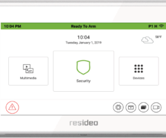
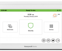
THE HOME PAGE
Name
Description
Time/Date
Displays current panels Time and Date.
Status Banner
Displays status of
the control panel.
Partition
Displays the current partition the keypad is viewing.
Wi
-
Fi Status
Displays the signal strength of your Wi
-
Fi connection
Weather
Displays the current temperature.
Automation
Menu
Displays the
Z
-
Wave device
menu
, Scene setu
p, Room Setup, Z
-
Wave setup menus.
Setup
Accesses the Setup Menus.
Training Videos
Access to view one of
11
available videos.
Slide Show
Accesses the Slide Show Setup.
Camera
Menu
Accesses the Camera Screen.
Emergency
(Panic)
Accesses the Emergency (P
anic) icons. Can be accessed from any screen.
Security
Menu
Accesses the control panel’s security options.
Multimedia
Menu
Accesses Camera, Event View, Picture, Video, and Message Menus.
TUXEDOW INSTALLATION AND SETUP GUIDE
11
SECURITY MENU
Introduction to Security System Operation
You c
an arm the system in one of three arming modes: Away, Stay, and Night. The following table lists the three different
arming modes and the results of each.
FEATURES FOR EACH ARMING MODE
Arming
Mode
FUNCTION
Exit
Delay
Entry
Delay
Perimeter
Armed
Interior
Armed
AW AY
Touch
to arm when no one is staying
on the premises. When armed in
AWAY
, the system sounds an alarm if
a protected door or window is opened,
or if any movement is detected inside
the premises.
Yes
Yes
Yes
Yes
STAY
Touch
to arm when you a
re staying
home, but might expect someone to
use the entrance door later.
When armed in
STAY
, the system
sounds an alarm if a protected door or
window is opened, but you may
otherwise move freely throughout the
premises.
Yes
Yes
Yes
No
NIGHT
Touch
to
arm when you are staying
home and do not expect anyone to use
the entrance door.
Your installer may
have configured NIGHT Mode
differently; have the installer describe
the actual settings of this mode.
Yes
Yes (set for Away or
Stay Mode)
No (set for Inst
ant or
Maximum Mode)
Yes
Yes (set for
Away or
Maximum
Mode)
No (set for Stay
or Instant
Mode)
See Night Mode
note below
NOTE:
Night Mode (on Residential Panels Only) arms all perimeter zones plus all zones listed in Zone List 5.
IMPORTANT:
On Commercial s
ystems, “Away Auto Stay” mode is shown as “Away” mode (with all zones monitored).
However, some interior zones may not be armed.
NOTE
S
•
The Voice Status Sounder Icon (
) indicates the Voice feature. Touch the Voice Status Sounder Icon to hear system
statu
s. Wait 3 seconds and touch
again to hear Zone Faults or Trouble conditions. Voice status will annunciate even if
Voice mode and Chime mode are disabled. Note that the Voice feature must be enabled (by the installer) for this icon to
function correctly dur
ing an alarm condition.
•
There is a communicator delay of 30 seconds. This delay will prevent a report to the central station if the control panel
is disarmed within 30 seconds after an intrusion alarm is triggered. This delay can be removed, or it can be increased
up to 45 seconds at the option of the user by consulting with the installer. Note that emergency, carbon monoxide, and
fire
-type alarms are normally reported without delay. TUXEDOW INSTALLATION AND SETUP GUIDE
12
Commercial System Notes
•
If the Aux Relay function is set for alarm silenced by User Code + # + 67, this command may only be entered in the
console emulation mode.
•
Do not use the common lobby logic function.
•
If fields 2*22 (Display Fire Alarms of other Partitions), 2*23 (Display Burg & Panic of other Partitions), or 2*24 (Dis
play
Troubles of other Partitions) are enabled, the zones that created the conditions cannot be viewed. You must go to that
zone's home partition to view.
•
If field 1*11 (Zone Bypass After Disarm) is enabled, you must use the Touchscreen’s Console Emulation
Mode and the
commands “Code” + “64” (unbypass all) or “Code” + “6” + “Zone Number” (unbypass zone) to remove zone bypasses.
•
The First to Alarm Display Lock feature (field 1*10) is not supported by the Touchscreen.
•
RF Low Battery messages are not supported
by the Touchscreen except in the Show Zones screen where a Battery Icon is
displayed for the zone with the low battery.
General Notes
•
“Exit Error” and “Auto Arm Alert, Please Leave Now” messages are not displayed by the Touchscreen.
•
When the system has 61
50Vs or 6160Vs, and 6271Vs attached, the Additional Console setting in the 6150Vs (displayed as
A on the 6150V) must be set to 1 and the Additional Console setting in the 6160Vs must be set to Yes.
•
For additional troubleshooting procedures, refer to the Control Panel Installation Guide.
Panel Default Displays
The Security screen displays an Icon(s) if a panel fault occurs. The following lists the Icons that are displayed to the left
of the
Panic icon.
ICON
MEANING
AC Loss;
The system is not receiving
AC power.
Bell Failure;
The system bell or siren has a problem.
Note:
This Icon is displayed when interfacing with residential panels only.
Expander Failure;
The system has a failure in an expansion module.
Low Battery;
The system battery, that po
wers the system during an AC power loss, is low.
LRR Supervision Failure;
The Communication Device used to communicate with the central station has a supervision failure.
Max Attempts Exceeded;
The system has exceeded the maximum attempts to communicate with the Central Station.
Pager Failure; The system cannot communicate with an assigned pager.
Telco-
1 Cut;
The system is not able to communicate with the central monitoring station over the primary phone line.
Telco-
2 Cut;
The system is n
ot able to communicate with the central monitoring station over the secondary phone line.
Wireless Failure;
The system is not able to communicate with its wireless devices.
TUXEDOW INSTALLATION AND SETUP GUIDE
13
How to Arm the System
Arming the system in any mode is performed in the same way, as described below.
Note:
Close all perimeter windows and doors before arming.
Arm the system as follows:
ICON
ACTION
NOTES
1. From the Home screen, touch the
Security
icon.
2. Touch
the selected arming icon.
- a text message appears stating which
zones are arming and whether or not
there is an entry delay
- the screen changes to display the
remaining exit delay time, and
- the exit delay time continues to count
down to one.
NOTE:
If Quick Arm is Not enabled in your system, a
message to ent
er your User Code is received.
•
When the system is armed for Stay, Night Stay and
Instant mode, the touchscreen beeps 3 times.
•
When the system is armed for Away and Maximum
mode, you will hear steady beeps then rapid beeping
during the last 10 seconds of Ex
it Delay.
•
When exit delay time expires, the screen automatically
changes to indicate the system is "Armed".
Note: For CP
-01 installations, Maximum Mode cannot be used.
How to Display Faults
The Display Faults function is used when you see a “Not Ready F
ault” message and want to determine where the fault is and
what type of fault it is. To display faults, do the following:
ICON
ACTION
NOTES
1. Touch the following icons:
Security →
More Choices
→
Show
Zones
.
Select the down arrow to view faults.
The drop-down menu displays a listing of fault types. Select the
fault type to view, and a message of current status is displayed
on the screen.
As applicable, take corrective action such as closing a window or
door to correct the fault.
2. If the fault c
annot be corrected, you
may choose to bypass a zone by
selecting the zone and highlighting it
and then touching the
Bypass Selected
icon.
Distressed Zones Icons
Alarm
Troubles
Faults
Bypass
Low
Battery
All
How to Bypass Zones
The Bypass function is used when you want to arm the system with one or more zones left open. Bypassed zones are
unprotected and do not cause an alarm when violated while the system is armed.
•
Residential systems do not allow you to bypass fire, carbon monoxide or emergency zones. On commercial fire
systems, a specified user may be allowed to bypass fire, carbon monoxide and system zones if the user was
enabled by your system installer.
•
Limits apply as to how many zones can be bypassed at one time. These limits are ten zones on residential
systems and five zones on commercial systems.
To bypass zones, do the following:
ICON
ACTION
NOTES
1. From the Home screen, touch the
Security
and
More Choices
icons.
Note:
If any zones are bypassed or faul
ted, a
Display
Faults
icon is also displayed on this screen.
2. Touch
the
Show Zones
icon.
While the touchscreen is requesting and receiving the zone
data from the control panel, the screen displays "
Please
Wait!
". Then the zones, along with their cur
rent status, are
displayed.
4. Highlight the zone(s) to be bypassed and
touch the
Bypass Selected
icon.
5. Enter the 4-digit user code.
Note:
If zones have already been bypassed, the top of this
screen indicates “
Ready Bypass
”.
The screen is displ
ayed with the instructions "
To Bypass
Zones, Enter Code
".
6. Touch the
Refresh Data
icon.
The "More Choices" screen is displayed showing the
system status as
Ready
-Bypass
. TUXEDOW INSTALLATION AND SETUP GUIDE
14
How to Clear Bypassed Zones
A bypassed zone is automatically unbypassed when you disarm the system. If a zone is bypassed, you can remove the
bypass as follows:
SCREEN
ACTION
NOTES
1. Touch the
SHOW ZONES
icon.
While the touchscreen is requesting and receiving the zone
data from the control panel, the screen displays "
Please
Wait!
". Then the zones, along with their current status, are
displayed.
2. Touch the
CLEAR BYPASSES
icon.
3. Enter your 4-digit user code. The "More
Choices" screen is displayed showing the
system as
Ready to Arm
.
NOTE:
If the system is armed and you unbypass a zone, it
disarms the system. If zones are still faulted (not
ready) the system will indicate the status as “Not
Ready Fault”.
How to Disarm the System
IMPORTANT:
If you return to your home or business and the main burglary sounder is on, DO
NOT enter the premises, but
call the police from a nearby safe location. If you return to your home or business after an alarm has occurred and the main
sounder has shut itself off, the keypad beeps rapidly upon entering, indicating that an alarm has occurred during your
absence
.
LEAVE IMMEDIATELY and CONTACT THE POLICE
from a nearby safe location.
The system may be disarmed using either of two methods. One method is employed when you enter the premises and the
other is when you have been in the premises with the system armed (i.e., Stay and Night arming modes).
To disarm the system when entering the premises:
The touchscreen automatically displays the Entry Delay Active screen when you enter the premises.
ICON
ACTION
NOTES
1. Enter your 4-digit user code.
The partition is disarmed and the "Arming" screen is
displayed showing the system as
Ready to Arm
.
NOTE:
If you have a commercial system and a time
window has been defined for when you may disarm the
system, the system does not disarm if you are outsi
de that
time window.
To disarm the system when already in the premises:
ICON
ACTION
NOTES
1.
Touch
the
Disarm
button.
2. Enter your 4-digit user code.
To disarm Multi
-Partitions do the following:
ICON
ACTION
NOTES
1. Touch the
Security
ico
n.
2. Touch the
Arm Multi
-Partition
icon.
3. Touch the
Disarm
icon.
4. Enter your 4-digit user code.
5. Highlight the partition(s) to disarm and touch
OK
, or touch
ALL
to disarm all
partitions.
All selected partitions should be disarmed, user can enter
multi
-partition list to check the status of partitions.
TUXEDOW INSTALLATION AND SETUP GUIDE
15
How to Check the Status of Other Partitions
This system supports between one and eight Partitions (depending on the system.) Partitioning enables a single physical
alarm system to control up to eight areas of protection (partitions) depending on the system you have purchased. Each
Touchscreen is assigned a default partition for display purposes, and shows only that partition's information.
NOTE:
A letter “H” following the partition name or number i
ndicates that this is the default partition for the touchscreen. For
example, if your physical site is a four
-apartment housing unit, your alarm system may be configured with four
partitions. Each apartment’s zones (door, windows, smoke detectors, etc.) ar
e assigned to separate partitions, giving
each apartment independent arming/disarming control of its own partition (area). A landlord or manager may be
granted access to all partitions, so he/she can control the entire system.
If a user is so authorized, a touchscreen in one partition can be used to perform system functions in another partition. (Note
that only those partitions authorized and programmed by the installer can be accessed in this manner.)
To check the status of other partitions, perform the f
ollowing:
ICON
ACTION
NOTES
1.
Touch the
Security
icon.
2. Select the "Current Partition" icon; in this
case it displays
P1 H
unless changed by
installer).
•
This screen displays the available partitions and their
current status.
•
The current partition is shown at the top of the display
(
P1
). To change this assignment, select the appropriate
partition
(e.g.,
touch
P2
to switch control to Partition 2)
,
then press
OK
.
•
After leaving this screen when using a residential panel,
the selected partition in the tou
chscreen automatically
reverts back to the touchscreen’s home partition after
two minutes. When using commercial panels, you must
select the touchscreen’s home partition to return to it.
•
A code may have access to some or all of the available
partitions.
3. Enter the code authorized to access other
partition(s).
If the code is accepted, the system displays
the partitions that user has access to.
Fire and Carbon Monoxide Alarm Operation
Your fire alarm system and carbon monoxide detector (if instal
led) is on 24 hours a day, providing continuous protection. In
the event of an emergency, the installed smoke, heat, carbon monoxide detectors automatically send signals to your
Control/Communicator, triggering a loud interrupted sound from the touchscreen. An interrupted sound is also produced by
optional exterior sounders. EVACUATE ALL OCCUPANTS FROM THE PREMISES IMMEDIATELY. Notify your Central
Station/Security Company immediately and wait for further instructions.
In Case of Fire Alarm
1.
A FIRE message
appears at your touchscreen and remains on until you silence the alarm.
2.
Should you become aware of a fire emergency before your detectors sense the problem, go to your nearest touchscreen
and manually initiate an alarm by
touch
ing the panic key assigned as
FIRE emergency (if programmed by the installer)
and hold down for at least 2 seconds.
3.
Evacuate all occupants from the premises.
4.
If flames and/or smoke are present, leave the premises and notify your local Fire Department immediately.
Silencing and Clearin
g a Fire/Carbon Monoxide Alarm
1. Silence, acknowledge, and clear the alarm by:
a.
For Residential Systems:
Touch
“Touch here to Silence” on the display to silence the alarm.
For Commercial Systems:
Enter your code. This silences and acknowledges the alarm a
nd disarming of the system
(if armed).
b.
For Residential Systems:
Touch
the
CLEAR
icon followed by your code. This acknowledges the alarm and the
disarming of the system (if armed).
For Commercial Systems:
Touch
the
CLEAR
icon followed by your code. The s
ystem attempts to clear the alarm
from memory. If NOT successful (i.e., smoke in the detector) the Security screen is displayed and the Display Faults
icon displays a “Not Ready Fault”.
c.
Touch
the
DISPLAY FAULTS
icon on the Arming screen. The faulted fir
e/carbon monoxide zone is displayed.
d.
Touch
the
CLEAR
icon and then enter your code. This clears the Fire Alarm/CO Alarm from the system.
2.
If the touchscreen does not indicate a
READY
condition after the second sequence, touch
the
DISPLAY FAULTS
key on
the Arming screen to display the zone(s) that are faulted. Be sure to check that smoke detectors/carbon monoxide
detectors are not responding to smoke, heat, or gas producing objects in their vicinity. In this case, eliminate the source
of heat, smoke or leak.
3.
If this does not remedy the problem, there may still be smoke/gas in the detector. Clear it by fanning the detector for
about 30 seconds.
4.
When the problem has been corrected, clear the display by entering the
DISPLAY FAULTS
icon on the Arming screen,
selecting the fire or carbon monoxide zone, touching the
CLEAR
icon and then entering your user code.
Note:
Contact your Central Station/Security Company for servicing if you have further problems with your system.
TUXEDOW INSTALLATION AND SETUP GUIDE
16
MORE CHOICES
How to Clear/Hide a Contro
l Panel Message
The Control Panel Message icon alerts the user to a control panel message. When a Control Panel Message is displayed, the
user has two options. User can clear the Control Panel Message immediately, or minimize the window and clear it at a l
ater
time.
To Clear/Hide the Control Panel Message, do the following:
ICON
ACTION
NOTES
1. To clear; touch
CLEAR
.
2. Enter your Authorized Code or,
3. To hide; touch
HIDE
to clear the Control
Panel Message later.
Once your
Authorized Code
is accept
ed, the Control
Panel Message is cleared.
If the alarm is still present, touch
CLEAR
again and then
enter your
Authorized Code
again.
Touch
the
HIDE
icon to address the condition later.
Advanced System Features
While most of the commonly used security fu
nctions are available from the touchscreen’s advanced user interface, there are
some less used, advanced features that can either be accessed through Console Emulation mode on the touchscreen or a
standard alpha keypad. To use features not supported by th
e touchscreen, refer to your Control Panel User Guide.
Console Emulation Mode
Console Emulation Mode allows you to use a touchscreen interface just as you would a regular system touchscreen. All
commands shown in Console Emulation mode can also be executed from a standard alpha keypad.
Notes:
•
It is recommended that you
do not
use the Console Emulation Mode to enter GOTO commands. Unsatisfactory operation
may result from issuing GOTO commands in Console Emulation.
•
Two
button press
panics (1 & *, 3 & #, and * & #)
do not
function in the Console Emulation Mode. The A, B, C, and D icons
do function if programmed as panic keys. Check with your system installer for details.
•
Commercial systems with Alpha keypads have a feature where if you
touch
a key for 5 seconds, you receive self
-help
messages about the
touch
ed key or holding the * key for 5 seconds to provide zone descriptors. These features do not
function in the keypad as all key
touch
es are instantaneous.
How to Enter Console Emulation Mode
To access C
onsole Emulation Mode, do the following:
ICON
ACTION
NOTES
1. From the Home screen, touch the
Security
icon
.
2. Touch the
More Choices
icon
.
3. Touch the
Console Mode
icon
.
Perform functions as you would from a standard alpha
keypad.
How to V
iew the Event Log
Your system has the ability to record various events in a history log wherein each event is recorded with the time and date of
its occurrence. The control panel must be programmed to record various system events in the installer program
ming mode.
To view the Event Log, perform the following:
ICON
ACTION
NOTES
1. From the Home screen, touch the
Security
icon
and then the
More Choices
icon.
2. From the
Event Logs
menu, select the
Events
drop-down arrow to view the logged history of
events. Your choices are: All Events, System,
Alarms, Troubles, Bypasses, and Open/Close.
NOTE:
While keypad is requesting and receiving the
event log data from the control panel, the "Event Log"
screen displays "
Please Wait!
"
The
Next>>
and
<>
and
<
System
Info
icons.
2.Touch the Remote Upgrade Setup button to
Enable Remote Upgrade.
3.Touch
Sync IP to Server to NEED This
information
Use the IP Address to
enter on a PC, Smart Phone or
Tablet Browser.
WHAT DOES SYNC IP TO SERVER DO?
System Setup
Touch
the
Setup,
and
System Setup
icons to access
Time/Date Setup, CS Setup, User Setup, Advanced Setup,
Tuxedo Sync, User Profile, Quick Programming
and
Cont
roller Initial.
See “
System Setup” section for detailed
information.
System WIFI
ICON
ACTION
NOTES
NOTE:
Supports 2.4GHz and 5GHz
frequencies
1. Touch
Setup
>
System WIFI
icons.
2. Select a Wi
-Fi network from the list to
connect to. Or, select
to add a new
Network connection. Enter the new
Network
name
SSID No
. and
Security
type; then
touch
Connect
.
3. Touch the
Setup
and
System
Info
icons;
the IP Address is displayed on the System
Information Screen. Enter the IP Address on
the keypad into a PC, Smart Phone or Tablet
Browser.
Use the Data Entry Keyboard to enter the required
information.
•
Use the
Shift
key for capital letters
•
Use the
BS
(Backspace) key to make corrections.
•
Touch
OK
•
Touch
abc
/
@#$
to switch between letters and symbols.
The TUXEDOW Keypads IP Address is used on a
standard web browser to control user functions such as
Security, Z
-Wave operation, and camera viewing.
DHCP Setup
By default, the touchscreen
is configured for DHCP. Once accessing
IP
, a
list of available network
s display
s. Choose the
desired network and enter the
Passphrase/Shared Key.
TUXEDOW INSTALLATION AND SETUP GUIDE
19
Manual Network Setup
The option to add a custom network is available by selecting
Add Network
. Connection to this mode requires the information
in the t
able
below
. Press
Save
when completed.
Required Field
Description
SSID
Network Name
Security Mode
The keypad will automatically detect the security mode of the router
Passphrase/Shared Key
Password to access the network
Advanced Options
(Optional)
Pro
xy Settings: Manual (Proxy Host Name, Proxy Port, Bypass Proxy for)
or Automatic (PAC URL required) and IP Settings (Static or DHCP)
Static Network
The option for a Static Network is only available
by manually adding the network
. Press the “Internet Connection Type” option
to allow the IP Address, Gateway
, Network Prefix Length
and DNS Server
1 and 2.
Supported Browsers
System Requirements
Recommended Browser
Windows XP SP2 and SP3, Win7, Win8
,
Win10
IE 8.0 and above, Chrome 30
-
42, Safari 5.0.2 &
abov
e, Mozilla 26 and above.
Android Mobile
ICS4.0 and above
iPad™, iPhone™
Default browser (iPhone Version iOS4, iPad®
Version iOS4 and iOS5, iOS6)
Android Tablet
Default browser (Galaxy
–
Android 2.3)
Win 8 tablet
Default browser
Other tablets, smart ph
ones
Might face some issues because it is not possible
to support all browsers.
NOTES
:
•
If JavaScript is disabled in any of the browsers then some of the features will not be populated
and functions may not work.
•
If the “Load Images” option is disabled on a smart device’s mobile browser, then images will not be populate on the pages.
•
Google Chrome version 42 and higher do not support the QuickTime plug in; video streaming will not work. This is the
same with Android Devices.
IMPORTANT:
Use the web browser to view cameras for non
-security purposes only. Camera streams viewed from the web
browser can stop without indication due to network connection issues.
Internet Explorer 11 and higher Note:
If the video streaming is not working, configure the browser f
or compatibility mode and
refreshed the web page.
Local Access
TUXEDOW’s
remote access option offers built
-in web hosting capability to access your system via any web enabled device.
TUXEDOW
can connect to a network router via Wi
-Fi. The
Account Login
me
nu accesses the username and password used
to for the connection. This can be a local connection or remote connection using port forwarding. Features of this page are
as
follows:
•
5 total users
•
Enabling or disabling
authentication for web server local access
•
Secure web server access (HTTPS)
Web Server IP Address Access
The
System Info
screen reveals the connected IP address. Any device with a browser connected to the same network as the
TUXEDOW
can access the webserver. This does not require authenticati
on (Username and Password). If this authentication
is desired, check the
Authentication for Web Server Local Access
check box
(on the Account Screen, see Account Setup
for more information), which can control who has access t
o connect by requiring a username and password. Unchecking the
box leaves the Web Server open for anyone to connect.
Connecting the
TUXEDOW
to a mobile device
To connect a mobile device to
TUXEDOW
, do the following:
Smart Phone or Tablet
1. Verify the TUXED
OW
is connected to the
Network
via Wi
-Fi.
2. Verify the Smart Phone, or Tablet, is connected to the same network as the TUXEDOW
(disable mobile data if needed.)
3. Open the browser and enter the IP Address on the keypad.
On a Personal Computer (PC)
1. Verify the TU
XEDOW
is connected to the Internet via Wi
-Fi.
2. Verify the PC is connected to the same network as the TUXEDOW.
3. Open the browser and enter the IP Address on the keypad.
TUXEDOW INSTALLATION AND SETUP GUIDE
20
Remote Access Browser Commands
Access to basic arming commands is available if using a Sm
art Phone or Tablet browser. Full access to keypad options is
available if using a PC.
NOTES
:
•
If left inactive, the web connection will disconnect after 10 minutes.
•
If using an iPad, iPhone or PC browser with low bandwidth on the mobile PC type theme, sw
itch to the mobile theme. To
switch to the mobile theme press
Switch Theme
in the lower left hand corner.
Not supported commands during remote or local access with a web browser in PC or Mobile Modes:
Security
Annunciate status
Multimedia
Picture/slide
show
System troubles
Camera 360 degree rotation
Emergency button
Camera Wi
-
Fi settings
Event logs
Recording settings
Show zones
Automation
Z
-
Wave device management
Setup
Account setup
Emergency button
Disp. & Audi
o setup
Rooms
IP setup
Remote scenes
System setup
Email setup
General
Weather
Voice setup
Training videos
Remote firmware upgrade
Troubleshooting
If the page does not populate, from the Home Screen press
Setup
>
System Setup
>
System Information.
1.
Press
Sync IP to Server.
2.
The message
“System IP sync to server is successful,”
when a successful connection is made.
3.
If no connection is present, the message “Keypad is not in the network. Please check the network connectivity.”
4.
If the keypad is connected to the LAN with no internet access, the message
“System IP sync to server has failed”
appears.
If Authentication for Web Server Local Access is enabled, and no user name and password is created, the browser will
produce the following message:
“Warning Remote access has been deactivated. Go to your Tuxedo’s login setup to
create an account for remote access.”
NOTES:
•
To correct this add a username/password and verify the user is enabled.
•
Browser may block access if the Secured Web Server Access (https) option is enabled. During remote login, if the
browser displays a Security
/Certificate
Error
this is not a threat and it is recommended that you continue.
Remote Access Using Port Forwarding
TUXEDOW
offers built
-in web hosting capabili
ty to access your system via any web enabled device. The local IP Address is
used on a standard web browser to control user functions. The home router must first be configured for port forwarding for
both HTTP and HTTPS ports, which port the local IP address. Refer to the router’s instructions for details on Port forwarding.
See the notes above for any security certificate errors and steps to be taken to proceed.
Account
For Remote Access and to create a browser log-on page for each user touch the
Accou
nt
icon
ICON
ACTION
NOTES
Touch the
Setup
and
Account
icons.
1. Enter a User Id, User Name and Password.
Check the appropriate box(s)
- SECURED WEB SERVER ACCESS
(HTTPS)
- AUTHENTICATION FOR WEB SERVER
LOCAL ACCESS
2. Touch
to save. Touch
to return to
the previous screen.
•
For Remote Access, and for higher security when
viewing from a web enabled device or PC on a different
sub-net, create a log-
in page for users. Enter the
required information for each field.
•
With HTTPS enabled, for remot
e access, ensure port
no 443 is open in the router. Also, browser will
generate a security warning before loading the
webpage. It is normal to accept the warning in order to
access the webpage.
•
Passwords must be eight alphanumeric characters,
include at
least one uppercase letter and one number.
•
Remote login is blocked after three failed attempts. To
restore, on the keypad click
Setup
>
Account
, press
the appropriate user
Disabled
icon >
Save
.
•
If left inactive, Web connections disconnect after 10
minu
tes.
TUXEDOW INSTALLATION AND SETUP GUIDE
21
DISP & AUDIO SETUP
You may access
Operating Modes, Backlight Off After
time,
To Homepage After
time,
Auto Slideshow After
time,
Selection
,
Temperature Unit
,
and
Clean Screen
from
the
Disp & Audio Setup
screen
.
Operating Modes
Operating modes provides access to
Chime Mode, Voice Mode, and Voice Chime
which allows you to turn the keypad
chime mode and voice mode on or off.
•
Chime Mode
– Keypad chimes whenever a door or window is open.
•
Voice Mode
– Keypad voice annunciates whenever a change in system status occurs.
•
Voice Chime
– The chime mode and voice mode are in effect with the chime beeps followed by voice annunciation.
Access the "Operating Modes" screen as follows:
ICON
ACTION
NOTES
1. From the
Setup
screen, touch the
Disp &
Audio Setup
icon.
2. Enter your “Authorized Code", if required.
3. Select
Chime Mode
or
Voice Mode
to turn
the mode on or off.
4. Touch
to save. Touch
to return to
the previous screen.
If the Chime Mode and Voice Mode are both selected, the
Vo
ice Chime is automatically selected.
It may take a few seconds for the Chime Mode to take
effect.
When the keypad exits the “Operation Modes” screen, your
selection is saved.
Adjust the Screen Timeouts
When the keypad is left idle, it automatically:
•
turns the “Backlight Off After” the selected backlight off time has expired (unless “Never” option is selected).
•
returns to the Home/Security screen after the selected “To Homepage After” time has expired (unless “Never” option is
selected), and if enabled, the “Auto Slideshow After” time begins the slide show.
To select the desired screen timeouts, from the Home screen, do the following:
ICON
ACTION
NOTES
1. Touch the
Setup
icon.
2. Touch the
Disp & Audio Setup
icon.
3. Enter your “Authorized Cod
e", if required.
4.
Touch
to select from the drop-down list
displaying the time period for each option.
5. Select
Fahrenheit (°F)
or
Celsius (°C).
If changes are made, when you exit a
n
Information
pop
-
up window displays “
Settings Saved
“
Settings include
:
Backlight Off After
X time,
Return
To
Homepage After
X time,
Auto Slideshow After
X time.
Touch
to save. Touch
to return to the previous
screen.
TUXEDOW INSTALLATION AND SETUP GUIDE
22
Clean Screen
With the exception of normal cleaning, the keypad
is maintenance free. Clean the touch-
screen as follows:
ICON
ACTION
NOTES
1. Touch the
Setup
icon.
2. Touch the
Disp & Audio Setup
icon.
3. Enter your “Authorized Code", if required.
4. Touch the
CLEAN SCREEN
button to
disable the keypad for 26 seconds.
5. Touch
Continue
to disable the touchscreen.
6. Touch
Cancel
to exit.
At the
"Touch Screen Disabled for =30 Seconds"
screen, the touchscreen should be wiped clean of
fingerprints using a mild soap solution and a soft cloth.
When the counter reaches zero, the window automatic
ally
closes and the touch-
screen is active.
A pop-up window displays "
Touch Screen will be
disabled so that you may wipe the screen clean. Please
use a damp, soft cloth. DO NOT use any liquids,
sprays, or ammonia-
based cleansers. Touch
CONTINUE to disable
touchscreen." **Panics cannot
be initiated during this process**
NOTE:
The
Emergency
screen cannot be accessed while running in the clean screen mode.
IMPORTANT:
Do not use an abrasive cleaning agent or abrasive cloth when cleaning the touch-
screen or
damage may
occur.
Routine Care
•
Treat the components of your security
system as you would any other electrical equipment. Do not slam sensor
-protected
doors or windows.
•
Keep dust from accumulating on the keypad and all protective sensors, particularly on
motion sensors and smoke detectors.
•
Keypad case and sensors should be carefully dusted with a dry soft cloth.
Do not spray water or any other fluid on the
units.
Brightness and Volume Control
From the Home screen, access the
Setup
screen as follows:
ICON
ACTION
NOTES
1. From the
Setup
screen, touch the
Disp &
Audio Setup
icon.
2. Enter your “Authorized Code", if required.
3. Move the bar left or right to increase or
decrease level of brightness or volume.
Changes are saved when you exit
this screen.
TUXEDOW INSTALLATION AND SETUP GUIDE
23
SYSTEM SETUP
Time/Date Setup
You can set the time and date from the
Time / Date
Setup screen.
•
When the time is set, it is stored in the touchscreen and sent to the control panel when you touch
the
Apply
icon and
answer
Yes
to the “Set
time on the
security system as well?”
prompt. Additionally, when using the touchscreen, the panel
may download its time into the touchscreen periodically after the clock is set
.
•
If
Get Time
is
touched, the keypad downloads the time and date from the control panel and
exits the Set Time & Date
screen.
Setting Daylight Savings Time
To set the daylight savings time, do the following:
ICON
ACTION
NOTES
1. From the Home screen, touch the
Setup
and
System Setup
icons.
2. Touch the
Time/Date Setup
icon; enter an A
uthorized Code.
3. Touch the
DST
icon if you want daylight savings time to affect
your system clock.
4. Set the “Start DST” time and then the “End DST” time by
touching the
Month
,
Weekend
and
Hour
that you want DST
to start.
5.
Touch
to save settings
.
If
DST On
is selected, the keypad adjusts
for Daylight Savings time at the month,
week and time chosen.
Make sure "DST On” is checked to enable
this feature.
Setting Current Time and Date
To set the current time, do the following:
ICON
ACTION
NOTES
1. Touch the
Time/Date Setup
icon; enter an Authorized Code.
2. Scroll to select the
Year, Month, Day, Hour, Minute, AM or
PM
to be displayed.
3. Use the drop-
down menu to select a format for
MMDDYY
and
12 Hour
or
24 Hour
to be displayed.
4. Touch
to save settings.
After each selection the window closes
automatically and the selection is
displayed.
Select if you want a 12-
hour or 24-hour
format for your time display.
A confirmation screen is displays:
“Time Setting Confirmation”
“Set time on the
security system as
well?”
Select
Yes
or
No
TUXEDOW INSTALLATION AND SETUP GUIDE
24
CS Setup
You may access
Options, ECP Address, Screen Security, Device Events, Code Authority, Panel Configuration, TC
Server Info.
Options
ICON
ACTION
NOTES
1. From the Home screen, touch the
Setu
p, System Setup
and
CS
Setup
icons.
2. Enter the
Authorized Installer Code.
3. Touch the
Options
icon.
4. Configure Options:
Weather Forecast:
Enable or Disable the Weather Forecast
on the home page.
Commercial:
Only available when in Automation Operating
Mode. Give you the option of Open, Close, and Night on the
Security screen.
5. Configure Operation Modes (See notes)
6.
Touch
to save settings.
Normal Mode:
Runs keypad in normal
operation, connected to a supported
control panel.
Safe Mode:
Se
e Safe Mode
Section
Demo Mode:
Does not require a control
panel to be connected.
Automation Mode:
Used for controlling
and automating the home without a
control panel attached.
See
Fi rst Time Setup
for more detailed
information.
ECP Address
ICON
ACTION
NOTES
1. From the Home screen, touch the
Setup
, System Setup
and
CS
Setup
icons.
2. Touch the
ECP Address
icon.
3. Enter
Authorized Installer
Code
4.. Touch the ECP Address
drop down menu and select the
desired address.
5. If using Total Connect, Set the RIS Automation ECP Address
by touching the drop down menu.
Check the Primary RIS
Device only if you are not using total connect.
6. Touch
to save settings.
(If changes w
ere made the
keypad will reset.)
See
First Time Setup
section for more
detailed information.
Screen Security
ICON
ACTION
NOTES
1. From the Home screen, touch the
Setup
, System Setup
and
CS
Setup
icons.
2.
Enter
Authorized Installer Code.
3. Touch the
Screen Security
icon.
4. If authority levels are correct, touch
or
to exit menu.
5. If changes are necessary, select the line to be changed and
the level of user to have acces
s. Options are Installer,
Master, Manager, Operator A, Operator B, Operator C, or
Anyone.
6. S
elect
to save
.
The Screen Security screen contains a list
of authority levels for Advanced Setup, CS
Setup, Display & Audio Setup, Event Logs,
Lighting, Message, Security, and
Time/Dat
e Setup.
It allows you to choose
which authority level is required to access
each screen.
TUXEDOW INSTALLATION AND SETUP GUIDE
25
Device Events
ICON
ACTION
NOTES
1. From the Home screen, touch the
Setup
, System Setup
and
CS
Setup
icons.
2. Enter
Authorized Installer Code.
3. Tou
ch the
Device Events
icon.
4. To reset, or clear, the events touch the
X
in the bottom right
hand corner of the screen.
The Device Events screen displays the
system events of the keypad only (resets,
time set, end user license accepted,
response types, etc.)
This is not the event log of the control
panel.
Code Authority
ICON
ACTION
NOTES
1. From the Home screen, touch the
Setup
, System Setup
and
CS
Setup
icons.
2. Enter
Authorized Installer Code.
3. Touch the
Code Authority
icon.
4. Enter t
he 4
-digit code.
5.
Touch
to go back to the CS Setup Screen or
to exit
.
Authority Level in
Panel
Matching
Authority Level in
Touchscreen
Access Level Chosen in
Touchscreen Screen Security
Installer
Master
Manager
Operator A
Operator B
Operator C
System Master
Master
No
Yes
Yes
Yes
Yes
Yes
Partition Master
Master
No
Yes
Yes
Yes
Yes
Yes
Standard User
Normal
No
No
No
Yes
Yes
Yes
Arm Only
N/A
No
No
No
No
No
No
Guest
Guest
No
No
No
No
Yes
Yes
Authority levels define the system functions
a particu
lar user can perform. Depending
on the authority assigned to you, there are
certain system functions you may be
prohibited from performing. The table
below describes the authority levels
available in the Touchscreen and provides
the equivalent authority level name found in
your alarm system manuals.
Panel Config
ICON
ACTION
NOTES
1. From the Home screen, touch the
Setup
, System Setup
and
CS
Setup
icons.
2. Enter
Authorized Installer Code.
3. Touch the
Panel Configuration
icon
to display the P
anel
Hardware version, Panel Revision, Number of zones, Number
of Partitions, Home Partition, Cal Support, and Sequence.
4. Touch
the
X
to delete the panel configuration (
the
Touchscreen resets and the panel configuration is
downloaded from the panel into
the Touchscreen.
) or touch
to go back to the CS Setup Screen or
to exit
.
A "Panel Configuration" screen is displayed
providing details of your system.
Touching
Delete
prompts you with a
confirmation screen displaying:
Are you sure you want to delete P
anel
Configuration? OK Cancel.
TUXEDOW INSTALLATION AND SETUP GUIDE
26
TC Server Info
ICON
ACTION
NOTES
1. From the Home screen, touch the
Setup, System Setup
and
CS Setup
icons.
2. Enter
Authorized Installer Code.
3. Touch the
TC Server Info
icon.
4. Touch
Diagnostics
to
test each server path.
5. Touch
the
TC
icon to view the list of enrolled Z
-
Wave devices.
This is where you can enable or disable devices from
showing up on Total Connect.
4. Touch
to go back to the CS Setup Screen or
to exit.
•
On Total Connect, the m
aximum number
of supported devices is 40 switches
(including Water Valves), 3 thermostats,
4 door locks and 3 Garage Door
Controllers.
•
TUXEDOW
supports 232 devices
(including the TUXEDOW
keypads) in the
Z-Wave network.
User Setup
User Setup
allows you to
Add a User
,
Delete a User
, and
Edit a User
. You may access User Setup from the System Setup
screen. Each user must be assigned a name with a corresponding 4-digit user code in order to gain access to various features
and functions. The maximum number of Us
ers that can be added is limited to the number of users that the
control
panel
supports.
Users for the system are programmed in a central user setup location that provides the specific questions for authorization
levels assigned to different users. You may want these users to be the same, but there are situations in which you may want a
user to have limited capabilities. These capabilities are defined by the Authority Level assigned each user.
Authority Levels
Authority levels define the system functions a particular user can perform. Depending on the authority assigned to you, there
are certain system functions you may be prohibited from performing. The following information describes the authority levels
that can be assigned through the keypad and provides the equivalent authority level name found in your alarm system
manuals. The authority levels that can be assigned are as follows:
Authority
Level
Functions
Equivalent System Name
Residential Systems
Commercial
Systems
Master
Can perform all securit
y functions, add/delete users in
assigned partition, program scheduled events, and
change partition master code
Partition Master
Level 1 Master
Normal
Perform security functions (arm, disarm)
Standard User
Level 3 Operator A
Guest
Can arm the system in a
ssigned partitions, but cannot
disarm the system unless the system was armed with
this code.
Note:
Do not assign this level if Quick Arm is enabled in
your system.
Guest
Level 4 Operator B
No Access
Used to restrict access from a partition.
N/A
N/A
TUXEDOW INSTALLATION AND SETUP GUIDE
27
How
to Add a User
ICON
ACTION
NOTES
1.
Touch
the
Setup
,
System Setup
,
User Setup
icons.
2. Touch
and enter your Authorized Master Code.
3.
Select the
Partitions
, and access level for this
user;
Master, Normal, Guest or No Access.
4. Touc
h the box next to
User Number
and e
nter an
“available” (3-
digit) user number.
5. Type the user name (6 characters max.; no spaces
between characters).
6. Touch
the box next to
RF Button Zone
(if used);
enter the 3-
digit RF Button Zone for this user.
7.
Touch
to
Save
the user information
or
touch
the
Back
arrow to return to the previous screen.
On the
Data Entry
screen, enter the user
information.
•
Use the
Shift
key for capital letters
•
Use the
BS
(Backspace) key to make
corrections.
•
The
@#$
key
is not available for use at this time.
These characters cannot be saved to the control
panel.
The authorized code for adding users is dependent
upon the
control
panel you are interfacing with.
Check your control
panel Users Guide to determine
who can add
users.
If assigning this user to wireless key, enter one of
the zone numbers of the keyfob (the wireless key
must be programmed first before it can be
assigned to a user).
Select the partitions, access level, and enter an
available user number for this us
er.
For available user numbers, see the control
panel instructions.
How to Add an Existing User to a Second Keypad
After adding a user to the first keypad, the same user can be added to a second keypad. From the second keypad go to “User
Setup” and enter the same user name and same user code (refer to How to Add a User
above). The second keypad will
automatically update the user information. Touch
Save
.
How to Delete a User
ICON
ACTION
NOTES
1.
Select the User you want to
delete.
2. Touch
the
X
icon on the lower right
-hand corner
3. Enter your Authorized code.
The
Confirm Delete
screen is displayed.
Three selections are available: add a user, edit a user,
or delete a user.
The authorized code for deleting, adding, and editing
users is dependent upon the control
panel you are
interfacing with. Check your control
panel User Guide
to determine who can delete, add, and edit users.
How to Edit a User
Note:
You cannot edit a User’s
name
or
number
. To modify a User name or number, you must delete the User and re-
enter
User.
Edit a user as follows:
ICON
ACTION
NOTES
1. Select the User you want to edit.
2. Enter your Authorized code.
3. Select the options needed for this user
and
touch
to
Save
.
Three selections are available: add a user, edit a user, or
delete a user.
Note:
The authorized code for deleting, adding, and editing
users is dependent upon the control
panel you are
interfacing with. Check your control
panel User Guide to
determine who can delete, add, and edit u
sers.
TUXEDOW INSTALLATION AND SETUP GUIDE
28
Advanced Setup
Advanced Setup allows access to
Power Mode Setup, Night Setup, Keypad Reset, End
-user License
and
Factory Default
menus.
At any time when a test is not being performed, you can touch the back icon to return to the previous screen,
or touch the home icon to return
to your home page.
Residential System Notes
•
If the Clean Me option is set, when the maintenance signal is received a “Fire Maintenance” message and the Display Faults
icon is shown. However, if you display the faults, zone 1 is not shown as a faulted zone.
•
If RF Jam Reports are selected and RF Jam is detected, the User Authorization screen displays “Trouble ZN100 RF
Receiver”. If you enter the console emulation mode, the display shows “Check 90 RF Receiver Jam”.
•
Do not use the Custom Word reminder feature.
Power Mode Setup
To set the Power Mode functions, from the Home screen,
touch
the
Setup
,
System Setup
and
Advanced Setup
icons.
ICON
ACTION
NOTES
1. Enter your Authorized Code and
touch
the
Power Mode
Setup
icon. Check the box to enable
Power Save Mode
.
2. Select the option to
Turn off Network
or
Override Display
Settings.
Touch
to save
settings.
Touch
to return to the
previous screen.
Night Setup
To set the NIGHT function, from the Home screen, to
uch
the
Setup
,
System Setup
and
Advanced Setup
icons.
ICON
ACTION
NOTES
1.
Enter your Authorized Code and
touch
the
Night Setup
icon.
2. Select the arming mode to be activated when
NIGHT
is
selected on the Arming screen.
The
NIGHT
icon can be set to arm th
e system in
one of five modes:
•
Away
- Arms all zones with entry delay.
•
Stay
- Arms perimeter zones with entry
delay.
•
Instant
- Arms perimeter zones without entry
delay.
•
Maximum
- Arms all zones without entry
delay. Not to be used for ANSI/SIA CP
-01
instal
lations.
•
Night (Residential Panels Only) –
Arms all
perimeter zones plus all zones listed in
Zone List 5.
Touch
to save
settings.
Touch
to return
to the previous screen.
Keypad Reset
To activate the Keypad Reset function, touch
the
Setup
,
System
Setup
and
Advanced Setup
icons.
ICON
ACTION
NOTES
1.
Enter your Authorized Code and
touch
the
Keypad Reset
icon.
2. Select
OK
to reset (power cycle)
or Cancel to quit.
The message is displayed:
Processor Reset: Are you sure you want to
reset?
Panel information is downloaded
TUXEDOW INSTALLATION AND SETUP GUIDE
29
End User License
To view the Privacy Statement and End-user License Agreement, touch
the
Setup
,
System Setup
and
Advanced Setup
icons.
ICON
ACTION
NOTES
1. Enter your Authorized Code and touch
the
End
-user
License
Touch
Back
or
Hom
e
.
Factory Default
To restore the TUXEDOW keypad to factory defaults,
touch
the
Setup
,
System Setup
and
Advanced Setup
icons.
ICON
ACTION
NOTES
1.
Touch
the
Factory Default
icon.
All settings will be erased and the keypad will
reset!
Select
OK
or
Cancel
.
Tux
edo
Sync
To access the
TUXEDOW
Device Synchronize Management screen
touch
the
Setup
and
System Setup
icons
.
ICON
ACTION
NOTES
Use to Discover button option to discover other TUXEDOW’s on the same network.
Select from the following actions:
DISCOVER TUXEDO
: Automatically searches for any TUXEDOW on the same network.
ADD
: You can manually add a TUXEDOW by entering the Name, IP Address, MAC and Model number.
EDIT
: Change the name of the TUXEDOW.
REMOVE
DEVICE
: Removes TUXEDOW from the list.
REMOVE
ALL
: Removes all TUXEDOW’s from the list.
SYNC
ZWAVE
DEVICE
NAME
: Allows you to synchronize the Z
-Wave device names on the secondary
TUXEDOW
controllers
.
User Profile
To access a user’s important operation information,
touch
the
Setup
and
System Setup
icons
.
ICON
ACTION
NOTES
View or change a user’s Name, Region, Area Code, Tuxedo Name, Mobile No., and E
-
mail Id.
Touch
back or home when done.
Touch
to save. Touch
to return to the previous screen.
TUXEDOW INSTALLATION AND SETUP GUIDE
30
Quick Programming
Used to access bas
ic programming of the control panel
, touch
the
Setup
and
System Setup
icons
.
ICON
ACTION
NOTES
1.
Touch
Setup
,
System Setup
, and
Quick
Programming.
2.
Enter
Authorized Installer Code
and keypad
says “Communicating with control panel” and
the status bar display “Panel Busy
Programming” when it is in programming
mode.
•
Not every security panel supports quick
programming, Check the control panel
documentation to make sure it supports quick
programming. Choose Abort if the control panel
does not support it or Continue to enter quick
programming. Choosing Continue on
unsupported control panels may result in the
device resetting.
•
Follow the menus and prompts to program the
control panel.
•
Only the residential panels support the Quick
Programming Mode.
Quick Progr
amming Menus
Menu
Programming Locations
Phone Account
Primary
phone, secondary
phone
, download phone
and account number for partitions
1 and 2.
Reporting
Select Yes or No for Alarm Restore, Trouble, Bypass, AC Loss, Low Battery, Test, RF
Low battery, or
select
All
to enable all events.
System Reports
RF Jam, Log Full, Open Report, Close Away, Close Stay, Cancel, Exit Error, All.
Timing & Misc
Exit Delay, Entry Delay 1, Entry Delay 2, Installer Code, Auto Stay, Alarm Sound
Time, and Fire Sounder Time Out
.
Zone Programming
Send Report, Input Type, Library (Vocabulary), Part (Partition),
Type (Zone Type),
Resp (Response Time), Config (Hardwire Type).
Controller Initial
To access the
Controller Initial Setup Wizard,
touch
the
Controller Initial
icon.
ICON
ACTION
NOTES
Step 1 of 3: Wi
-
Fi Setup
–
Connected to guest
Select a network from the list of available networks and enter the password. Or, touch
to set up a new
network name (SSID), security option (WEP, WPA/WPA2 PSK) and password. Touch
Connect or
Cancel.
Touch
NEXT
. Follow the prompts.
Step 2 of 3: Important operation information
Enter the Name, Region, Zip Code, Tuxedo Name, Mobile No, E
-mail Id for this user and
touch
NEXT
.
Step 3 of 3: Remote Login Setup
Enter the User Id, User Name and Password for this user.
Check the box
- SECURED WEB SERVER ACCESS (HTTPS)
Check the box
- AUTHENTICATION FOR WEB SERVER LOCAL ACCESS
Touch
FINISH to complete the initial setup wizard.
31
DEVICES (AUTOMATION)
The TUXEDOW Home Automation System with web hosting capability is equipped with Security S0/S2 enabled Z
-Wave
technology and is designed to automate devices in a home control network. Security S0/S2 encrypts messages to other Z
-
Wave Security S0/S2 enabled devices thereby ensuring the authenticity and securi
ty of all communication. The
keypad allows
you to easily add and control multiple devices with the touch
of a button. View the Training Videos and follow the instructions
below to Enroll (add) devices into your home control network.
U
L
Automation functi
onality is supplementary only and has not been evaluated by UL.
Access control functionality has not been evaluated by UL and may not be used in UL Listed applications.
To access the automation touch
Devices
.
Z-Wave Device Management Icons
Icon
Description
Icon
Description
Icon
Description
ADD DEVICE
Includes (Enrolls)
devices into the
network.
REMOVE
FAILED
Removes all failed devices
from the device list.
MORE
Accesses the
REPLACE
FAILED and Z
-
WAVE DEFAULT
options
REMOVE
DEVICE
Excludes (Removes)
devices from the
network.
DEVICE
SETUP
Edit the device name,
chan
ge the icon, and view
the Association details of the
selected device.
REPLACE
FAILED
Replaces a
selected failed
device.
ABORT
OPERATION
Aborts or cancels the
ADD/REMOVE DEVICE
action.
DEVICE
SEARCH
Searches for a selected
device and updates the
status.
Z-WAVE
DEFAULT
Defaults the Z
-
Wave controller to
factory settings.
Devices Icons
Description
Devices Icons
Des
cription
ROOM
View and create rooms to make it
easier to find devices
THERMOSTAT
Access to Wi
-Fi thermostats
SCENE
Create scenes
for automated living,
such as open a door and a light
comes on.
GROUP
Create groups of devices for
use with Scenes.
SETUP
Z-Wave devices can be enrolled,
deleted, and other features
REFRESH
Refreshes the device list to
get the most up to date
status.
TUXEDOW INSTALLATION AND SETUP GUIDE
32
Z-Wave device Management Screen Device List
The “Z
-
Wave Device Management Screen Device List” is composed of 5 columns.
DEVID
Displays the device or “Node” ID displayed in numerica
l order as you “Include” or “Add” Devices
NOTE
: Once a device is excluded, that node number cannot be used again, unless the controller is
defaulted.
NAME
Displays default and custom device names
TYPE
Displays the Z
-
Wave device type (i.e. multilevel swit
ch, binary switch, entry controller, etc.)
INFO
Displays the following Icons:
Router:
Chain Link:
Pad Lock:
The device is a routing slave
and can be used as a
repeater.
The node (device) can
send unsolicited
messages to the
TUXEDOW
.
Secured Ne
twork Supported
STATUS
Displays the following messages:
Success Network
The node has reported a normal status report.
Failed
Communication with this device has been lost.
Update Success
Search was successful when running “Device
Search
” operation o
n a
device.
Update Failed
Search was unsuccessful when running
“
Device
Search
” operation on a
device.
Not in Secure Network
Device is expected to be secured (such as an entry controller, but failed to
receive the encrypted key. (Remove device and add again closer to the
TUXEDOW
.)
Up
d
ate Timed Out
This message appears when a device does not respond when requested
during a “
Device Search” is performed.
Include (Enroll/Add) Z-
Wave Devices
Each device must be installed according to the manufacturer’s instructions.
WARNING:
Automation is intended for lifestyle convenience. Do not use automation for life safety and property protection.
Include (Enroll) a Light, Switch or Outlet Module
Install a Z-
Wave Light, Switch or Outlet module as described below.
ICON
ACTION
NOTES
1. At the TUXEDOW Home screen:
a) Touch
the
Devices
icon and then
touch
the
SETUP
icon to display
“Z-Wave Device
Management” screen.
b) Touch
the
ADD DEVICE
icon.
2. At the device Module:
a) Touch
the
Function Key
on the device.
Note:
Z
-
Wave light modules may vary; follow the instructions
in the User’s Guide for your specific device to include (enroll)
properly into the Z
-Wave network.
•
If a dimmer module was included, an On/Off button and a
slide bar (to control dimmer) are dis
played.
•
If an on/off light/appliance module was included, an On/Off
button (to control the device) is displayed.
The keypad displays a series of messages:
“Start add device.
Please
touch
function key on device”
“Adding Controller Unit”
“Adding Slave Unit”
“Device added successfully”
33
Include (Enroll) a Resideo
Thermostat
Install
Resideo
Thermostat
s according to the manufacturer’s
instructions. Device should be mounted in the final location and
tested before adding it to the system.
Note:
Resideo
is not responsible for property damages due to improper setting of the thermostat modes.
To include a Resideo
Thermostat into a Z
-Wave network, do the following:
ICON
ACTION
NOTES
1. At the TUXEDOW Home screen:
a) Touch
the
Devices
and
Setup
icons to display the “Z
-
Wave Device Management” screen.
b) Touch
the
ADD DEVICE
icon.
2. At the Z
-Wave thermostat:
a) Select
Thermostat;
set the Time/Date.
b) Follow the instructions in the thermostat Installation
Guide for “Z
-Wave Inclusion”.
c) To co
mplete inclusion,
touch
Done.
d) Touch
Exit
to return to normal operation.
Note:
If installing another brand of thermostat,
follow the instructions in the Users Guide for that
specific thermostat to include properly into the Z
-
Wave network.
Note:
Some th
ermostats do not update temperature
status automatically i.e., Wayne Dalton.
The keypad displays a series of messages:
“
Please
touch
function key on device”
* If not using a Resideo
thermostat, inclusion
procedure may vary. Refer to the thermostat
instruct
ions for the inclusion procedure.
The keypad displays a series of messages:
“
Please
touch
function key on device”
“Adding Controller Unit”
“Adding Slave Unit”
“Device added successfully”
Include (Enroll) a Door Lock
Assemble the Z
-Wave door lock.
NOTE:
Be sure the door lock orientation/handedness is correct.
Refer to the Door Lock’s
Instruction Guide
and connect necessary cables, then install batteries. Include the door lock within 5 ft of the keypad; refer to
the Door Lock’s
Instruction Guide for enrol
lment procedure.
NOTE:
Program the user code in the control panel prior to programming that user code into the door lock. User Codes must
be 4-digits.
Enroll a door lock device as follows:
ICON
ACTION
NOTES
1. At the TUXEDOW Home screen:
a) Touc
h the
Devices
icon and then
touch
the
Setup
icon to display the “Z
-Wave Device
Management” screen.
b) Touch
the
ADD DEVICE
icon.
2. At the Door Lock:
a) Program the selected user code from the
panel; refer to Door Lock
User Guide
.
Note:
Door lock devices
may vary; follow the instructions in the
Users Guide for your specific door lock to include properly and to
program a new user code.
The keypad displays a series of messages:
“
Please
touch
function key on device”
“Adding to Security Network”
“Device added
successfully”
* Inclusion (enrollment) procedure may vary depending on the
door lock device. Refer to the door lock instructions for inclusion
procedure.
Note:
If software is upgraded on the TUXEDOW keypad, enroll
the door lock again and re
-
set the user c
ode in the door lock.
Wi
-Fi
Thermostat Programming
NOTE:
Follow the installation guide provided with the Resideo
Wi
-Fi enabled thermostat to join the Wi
-Fi network.
Enrolling
Press
Devices
>
Thermostats
(displays Wi
-Fi thermostat management page) >
Accoun
t
> enter the username and
password >
Save
.
NOTE:
Enrolling the Wi
-Fi thermostat in the
TUXEDOW
keypad synchronizes it to their Resideo
Total Connect 2.0 account.
Enrolling the same Wi
-Fi thermostat in Honeywell’s Total Comfort app produces a duplicate Wi
-Fi thermostat shown
in Honeywell Total Connect 2.0 app.
NOTES:
•
Account must be configured at:
www.mytotalconnectcomfort.com
•
The keypad must be connected to the internet to perform
the association.
•
If the ac
count is associated correctly the keypad
displays, “Account associated. Start loading devices.
Please wait...”
•
If the account association fails the keypad displays,
“Account association failed. Please try again later
.”
•
Wi
-Fi thermostat
s are
only renamed
using
the
comfort
app/web.
•
If using a secondary controller, the user name and
password for MyTotalComfort must be entered.
NOTE:
Scenes programmed in the secondary keypad
are local only (will not show up on Total Connect).
•
The thermostat must be associated with the primary
controller to use Total Connect Remote services.
•
Z-Wave
and
Wi
-Fi thermostats (max. 5) are
combined in
automation for a
maximum number of
20.
•
After successful association the
thermostat
is
controllable via
Total
Connect.
•
Hold and schedules from MyTotalComfort
can
’t be
changed from
the
Tuxedo. TUXEDOW INSTALLATION AND SETUP GUIDE
34
Removing
a Thermostat and/or
Account Association
To remove a Wi
-Fi thermostat from the
TUXEDOW
keypad, you must remove it from the total connect comfort account.
Once it synchronizes the thermostat will no longer appear.
To remove account association, press
Devices
>
Thermostats
(displays Wi-
Fi thermostat management page) >
Account
>
remove the username and password >
Save
.
NOTE:
Pressing
Save
removes the current association and
all
Wi
-Fi thermostats included automatically. The keypad
display
s, “Account Association Removed.”
Exclude (Remove/Delete) Z
-Wave Devices
Exclude (Remove) a Light, Switch or Outlet Module
To exclude a light, switch or outlet module from the Z
-Wave network, do the following:
ICON
ACTION
NOTES
1. At the
TUXEDOW Home screen
:
a) Touch
the
Devices
and
Setup
icons to
display the “Z
-Wave Device Management”
screen.
b) Highlight the device to remove and
touch
the
Remove Device
icon.
2. At the device module:
a) Touch
the
Function Key
to remove the
device from the keypad.
•
Remove Device
-clears the node from the keypad and resets
device to the default setting.
•
If the device is not removed, or to remove a defective device,
refer to the
Z-Wave Troubleshooting
section.
Exclude (Remove/Delete) a Resideo
Thermostat
To exclude a
Resideo
Thermostat from the Z
-Wave network, do the following:
ICON
ACTION
NOTES
1. At the
TUXEDOW Home screen
:
a) Touch
the
Devices
and
Setup
icons to display the
“Z-Wave Device Management” screen.
b) Highlight the thermostat and
touch
the
Remove
Device
icon.
2. At the thermostat:
a) Follow the instructions in the thermostat
Installation Guide
under “
Installer setup
” to
“Remove a Z
-Wave Networ
k Connection”.
b) Once the exclusion process is complete, touch
Done
; the thermostat is removed.
IMPORTANT:
Resideo
is not responsible for property
damages due to improper setting of the thermostat modes.
Remove Device
-clears the node from the keypad and
resets device to the default setting.
Note:
To remove a defective device, refer to the
Z-Wave
Troubleshooting
section.
Exclude (Remove/Delete) a Door Lock
To exclude a door lock module from the Z
-Wave netw
ork, do the following:
ICON
ACTION
NOTES
1. At the TUXEDOW Home screen,
touch
the
Devices
and
Setup
icons. The “Z
-Wave Device Management” screen
is displayed.
2. Highlight the device to remove and
touch
the
Remove
Device
icon.
3. On the door loc
k touch
the
Function Key
to remove the
device from the keypad.
Remove Device
-
clears the node from the keypad and
resets device to the default setting.
Notes:
•
If the device is not removed, or to remove a
defective device, refer to Z
-Wave Troubleshooting.
•
When excluding the door lock, the user code
associated with the door lock will remain in the
system. If needed refer to the panel
Installation
Instructions
on how to remove this user code.
Abort a Z
-Wave Action
ICON
ACTION
NOTES
1. At the TUXEDOW Home screen:
a)
Touch
the
Devices
and S
etup
icons to display the “Z
-
Wave Device Management” screen.
b) Select the device name from the list and touch
the
ABORT OPERATION
icon to abort that process.
If inadvertent
ly a wrong selection was made, (add,
delete, or remove failed device) user can
touch
the
ABORT OPERATION
icon to abort the process.
35
Remove Failed Devices
ICON
ACTION
NOTES
1. At the
TUXEDOW Home screen
:
a) Touch
the
Devices
and
Setup
icons to
display the “Z
-
Wave Device Management” screen.
b) Touch the
Remove Failed
icon
This option removes any Z
-
Wave device that has
failed from the list
Device Setup
ICON
ACTION
NOTES
1. At the
TUXEDOW Home screen
:
a) Touch
the
Devices
and
Setup
icons to display the “Z
-
Wave Device Management” screen.
2. Highlight the Z
-Wave device to edit
3. Change the following:
Device Name
: Allows you to edit the device name
Display Icon
: Allows you to change the icon used for this
device.
4.
Device Associati
on: See NOTES.
Each Z
-
Wave enabled device has a maximum
number of secondary controllers, in which it has
the ability to send updates. Example, a
thermostat may have the ability to send up to
five additional TUXEDOW’s
on the same
network. However, other man
ufacturers may
not have that ability
.
Replace Failed Device
ICON
ACTION
NOTES
1. At the
TUXEDOW Home screen
:
a) Touch
the
Devices
and
Setup
icons to display the “Z
-
Wave Device Management” screen.
b) Select a failed device
c) Touch
More
d) To
uch
the
Replaced Failed
icon.
Replace Failed Device option walks you through
replacing a failed device. Follow the on screen
prompts
.
Default the Z
-Wave Controller
ICON
ACTION
NOTES
1. At the
TUXEDOW Home screen
:
a) Touch
the
Devices
and
Setup
icons to display the “Z
-
Wave Device Management” screen.
b) Touch
More
c) Touch
the
Z-Wave Reset
icon to delete all devices from
the controller
and reset to factory defaults
.
d) Touch
the
Yes
to continue
or
No
to cancel
button.
The message is displayed:
WARNING!! This Z
-WAVE controller is about to be
factory defaulted and will lose all devices in the
enrolled list. All Z
-WAVE devices must be re-
enrolled after this reset. Each device will have to
be excluded before it can be re
-enrolled.
This process performs a Z
-Wave SetDefault
command.
Please use this procedure only when the network
primary controller is missing or otherwise inoperable.
Scene Setup
The “Scene” feature is used to control the function of a single device, or multiple devices based on pr
e-set Conditions,
Triggers, and Actions. When the trigger/condition occurs, the action is executed. Define a Scene as follows:
ICON
ACTION
NOTES
1. At the
TUXEDOW Home screen
:
a) Touch
the
Devices
and
Scene
icons to display
the “Z
-Wave Device M
anagement” screen.
b) Touch
Add
to set up functions for this Scene.
c) Enter a
Scene Name
and
touch
OK
.
d) Select a “Condition,” “Trigger,” and “Action” that
you want to occur for this Scene. See example
below.
Enter the new device name by entering it
on the data entry
keyboard.
•
Use the
Shift
icon for capital letters.
•
Use the
BS
(Backspace) icon to make corrections.
The
@#$
icon is not available for use at this time.
Confirmation
Do you want to save this scene? Yes or No
After each selection
tou
ch
Save!!
Scene Icons
Add
Edit
Delete
A Scenes must have at least a trigger and 1 action to work.
Enter the event to trigger the scene in the Trigger section. The
Condition section is optional.
TUXEDOW INSTALLATION AND SETUP GUIDE
36
Scene Rules
•
Triggers and Conditions include: Tim
e setting, Security mode, Thermostat setting, Door and Garage Door status and Water
Valve status.
•
Actions include: Security mode, Lights on/off, Thermostat setting, Door and Garage Door Lock status
, Water Valve status
and recording.
•
Each Trigger event can have up to 3 Actions.
•
A Trigger event and Condition cannot be the same (i.e., if setting a Trigger event for Security, you cannot set a Security
Condition).
•
A total of 10 local
Scenes can be created.
However, it can view 20
scenes remotely from TotalConnect2.0
•
On commercial panels the programming option for “Global Keypad” must be set to “0” for some Scenes to work properly.
Note
: Determine if you need a Condition. The Condition is a ‘pre-condition’ set to occur prior to a trigger event. See example
below
.
Example
:
Turn the lights on, when the system is disarmed, only at night.
(Condition)
... “only at Night”
...Set the
TIME
condition (enter the
Start Time
and
End Time
).
(Trigger)
... “when the “system is Disarmed”
...Set th
e Trigger to
SECURITY:
System
Disarm
(Action)
...
“
Turn the “lights ON” ...
... Set the Action to
LIGHT:
ON
Critical Events
Check the
Critical Event
check box to record and store a maximum of two events even when the SD card is not available
. If
more than two critical events occur, then the older one is replaced by the latest event
Scene Setup Options
Conditional Options
– After each selection touch
SAVE!!!
Defines an optional event that puts a condition on the trigger. If a condition is set
, the condition must exist at the time of the
trigger for the action to occur. Conditions include the same categories as triggers. However, conditions cannot be set with t
he
same category as the trigger. (ex., if setting a trigger event for security, you c
annot use security as a condition).
In the “Condition” box, touch
the
Add
icon.
To set the time
, touch
the
TIME
button:
“Set the occurrence” to
Repeated
, or
Once
. If “Repeated” was selected, choose the
desired days of the week; if
ONCE
was selected
Ente
r Date.
The Time can be set to execute automatically at
Sunrise
or
Sunset
by
touch
ing the
Sunrise
/
Sunset
option.
Note:
The Sunrise/Sunset feature is dependent on the “Region” selected in
the “Weather Forecast” section and requires internet access for accur
acy. Or, touch
the
Timer
button (to limit the scene to
execute only from within a specified time window) and touch
on the “hour/minutes” displayed to enter the desired time on the
data entry keyboard. Touch
on
AM/PM
to change the setting.
To set the secur
ity mode
, touch
the
Security
icon
and select:
DISARM
,
NIGHT,
(triggers upon arming away),
AWAY
SECURED, STAY
(triggers when exit delay has expired)
and
ALARM.
To set the thermostat settings
,
touch
the
Thermostat
icon
and select a
Thermostat Device
from the
drop-
down menu. Use
the
ABOVE
and
BELOW
buttons to increase/decrease the temperature or touch
the
Temperature Value box and enter 2 digits
for the desired temperature.
Note:
Test thermostats first to ensure proper function in the Scene feature.
To set t
he door lock status
,
touch
the
Door
icon
and select a
Door
device from the drop-down menu (see notes below).
Select
LOCKED
or
UNLOCKED.
To set the zones
, touch
the
Zones
icon
and select a zone from the drop-down menu. Select Restore,
Alarm
or
Fault
.
Note
: Do not use zone Restore
option in the Condition field.
To set the garage door lock status
, touch
the
Garage Door
icon
and select a
garage door
device from the drop
-down menu
(see notes below). Select the Condition; OPENED
or
CLOSED
.
To set the Water Val
ve status
,
touch
the
Water Valve
icon
and select a
Water Valve
device from the drop
-down menu (see
notes below). Select the Condition; OPENED
or
CLOSED
.
To set the zones
, touch
the
Zones
icon
and select a zone from the drop-down menu. Select Restore,
Ala
rm
or
Fault
.
Note: Do not use zone Restore
option in the Condition field.
Trigger
Options
– After each selection touch
SAVE!!!
In the “Trigger” box, touch
the
Add
icon.
To set the time
,
touch
the
TIME
icon
and “Set the occurrence” to
Repeated
, or
Once
.
If “Repeated” was selected, choose the
desired days of the week; If
ONCE
was selected,
Enter Date
. The Time can also be set to execute automatically at
Sunrise
or
Sunset
by
touch
ing the
Sunrise
/
Sunset
option. Note: The Sunrise/Sunset feature is dependent on
the “Region” selected in
the “Weather Forecast” section and requires internet access for accuracy. Or, touch
the
Timer
button (to limit the scene to
execute only from within a specified time window) and touch
on the “hour/minutes” displayed to enter the d
esired time on the
data entry keyboard. Touch
on
AM/PM
to change the setting.
To set a security mode
, touch
the
Security
icon
and select:
DISARM
,
NIGHT, AWAYSECURED
,
AWAY
,
STAY
,
ALARM
(for residential panels only).
37
To set the thermostat settings
,
touch
the
Thermostat
icon
to select the
Thermostat Devices
from the drop down menu.
Use the
ABOVE
and
BELOW
button to increase/decrease the temperature range or touch
the
Temperature Value
box and
enter 2 digits for the desired temperature.
Note:
Test thermostats first to ensure proper function in the “Scene” feature.
To set the door lock status
,
touch
the
Door
icon
to select a
Door
device from the drop-down menu (see notes below). Select
LOCKED,
UNLOCKED
or
CODE UNLOCKED
.
To set the garage door lock status
, touc
h the
Garage Door
icon
to select a
Garage Door
device from the drop-down menu
(see notes below). Select
OPENED
or
CLOSED
.
To set the Water Valve status
,
touch
the
Water Valve
icon
and select a
Water Valve
device from the drop-down menu (see
notes below). Select the Condition;
OPENED
or
CLOSED
.
To set the zones
, touch
the
Zones
button and select a zone from the drop-down menu. Select
Restore
,
Alarm
or
Fault
.
Note: Do not use zone Restore in the Condition field.
Action Options
– After each selection touch
SAVE!!!
In the “Action” box,
touch
the
Add
icon.
To set the security mode
,
touch
the
Security
icon
and select:
DISARM
,
AWAY
,
STAY
,
NIGHT
, DISARM WITH CODE
. Enter
User Code,
if required.
To set the light on/off
, touch
the
Light
icon
and select a
Lighting De
vice
OR Lighting Device Group from the drop down
menu; set the action to
ON
or
OFF
and if it is a dimming switch set the desired dim level
. Touch
the
ON FOR TIME
button (to
limit the scene to execute only from within a specified time window) and touch
on t
he “hour/minutes” displayed to enter the
desired time on the data entry keyboard.
Touch
on
AM/PM
to change the setting.
To set the thermostat settings
,
touch
the
Thermostat
icon
and select a
Thermostat or Thermostat Group
from the drop-
down menu. Touch
the
Set
Mode
button to set the Action to “Off”, “Heat”, “Cool” Auto or EM Heat. Touch
the
Set Energy
button and select from “Save Energy” or “Normal” energy mode. Touch
the
Set Point
button and enter a set point value for
“Heat Point” and “Cool Point”.
Note:
Test thermostats first to ensure proper function in the Scene.
To set the door lock status
, touch
the
Door
icon
and select a
Door Device
from the drop-
down menu (see notes below). Set
the action to
LOCKS
or
UNLOCKS
.
To set the garage door lock status
, touch
the
Garage Door
icon
to select a
GARAGE
Door
device or
GARAGE DOOR
GROUP
from the drop-down menu (see notes below). Select
OPENED
or
CLOSED
.
To set the Water Valve status
,
touch
the
Water Valve
icon
and select a
Water Valve
device or
Water Valve Group
from the
drop-down menu (see notes below). Select the Condition;
OPENED
or
CLOSED
.
To set camera recording
, touch
the
Recording
icon to select the associated camera to record.
Note
: requires the MicroSD
card.
Notes:
1. Motorized door lock bolts physically lock and unlock the door when activated, but if the door lock installed is a non-
motorized type, activation allows the door to be manually unlocked without a key. See
Compatible Devices
section for
further infor
mation.
2. Some thermostats do not update temperature status automatically (i.e., Wayne Dalton).
3. When using a Kwikset Smartcode Electronic Deadbolt door lock (in a Scene that is programmed to trigger when unlocked)
the Scene does not trigger if using a
key; enter a user code.
Create a Room
Multiple devices can function as a group by associating them in a “Room”. Follow the procedure below to create a Room.
ICON
ACTION
NOTES
1.
Touch
the
Devices
icon and
Room
icons.
2. Touch
the
ADD
icon and enter a r
oom name on
the “Data Entry” keyboard.
3. Touch
SAVE
.
4. Highlight the device(s) from the list that you want
to add to this Room and touch
the
SAVE
icon.
Room names (i.e., All, etc.) are displayed across the top to the
screen.
Enter the new device name by entering it on the data entry
keyboard.
•
Use the
Shift
icon for capital letters.
•
Use the
BS
(Backspace) icon to make corrections.
The
@#$
icon is not available for use at this time.
Use the
Edit
and
Delete
icon to rename, or delete a room.
Room Setup I
cons
ADD
EDIT
DELETE
SAVE
TUXEDOW INSTALLATION AND SETUP GUIDE
38
Setting a Secondary (Keypad) Controller
After all Z
-Wave devices have been enrolled into the Primary (Keypad) Controller, the device information can be downloaded
to a Secondary (Keypad) Controller. Keep the controll
ers within 10 feet of each other, apply power to the Secondary Controller
and do the following:
ICON
ACTION
NOTES
1. At the Primary Controller:
a) Touch
the
Devices
and
Setup
icons to display the
“Z-Wave Device Management” screen.
2. At the Primary C
ontroller:
Touch
Add
.
3. At the Secondary Controller:
a) Remove any Z
-Wave devices that have been
added.
b) Touch
More
>
Learn Mode
and wait for the
controllers to exchange data.
NOTE:
This process
may take several minutes depending on the size of
your
Z-Wave network.
If used for Remote Services, TUXEDOW should not
be configured as a secondary controller. See the
Remote Services
section.
Note:
Up to 232 Secondary Controllers can be
added.
When the Primary Controller
icon is touched, the
message is displayed:
“Please remove all Z
-wave devices from network
first”
To default (or remove all Z
-Wave devices) the
controller
touch
Devices > Setup > More > Z
-Wave
Default.
NOTE
: Only touch
this on the TUXEDOW
that is to be th
e secondary controller. Defaulting the
primary controller loses all Z
-Wave devices.
The message is displayed:
“Scanning for
Devices”
The message is displayed:
“Updating Devices.
Please Wait”.
When the device information from the Primary
Controller is downloaded to the Secondary
Controller:
•
the Secondary Controller displays,
“Controller
Add Success”
•
the Primary Controller displays,
“Device Added
Successfully”
Updating Controllers (Keypads) with New or Removed devices
When devices are added, or removed from the Z
-Wave network, the device information needs to be updated in the
Controllers. To update this information, you
do not
have to remove the device first. From the Primary controller, do the
following:
ICON
ACTION
NOTES
1.
Touch
Add
on Primary
controller.
2.
Touch
Devices
>
Setup
>
More
>
Learn Mode
on Secondary controller.
The controller scans for device changes.
The message is displayed:
“Devices added Successfully”
Removing a Secondary Controller (Keypad)
To remove the Secondary controll
er, do the following:
ICON
ACTION
NOTES
1. At the Primary Controller keypad:
a)
Touch
Delete
.
2. At the Secondary Controller keypad:
a)
Touch
Delete
.
Both keypads will display,
“Device Removed”
and the Secondary
Controller keypad will revert back to the Primary Controller.
39
Z-Wave Troubleshooting
Remote Services
The TUXEDOW
™ supports Remote Services for controlling Z
-Wave devices and scenes remotely from an associated Total
Connect account.
The following describes the related features:
•
TUXEDOW [automation] can be controlled from a smart phone, i
-Pad
TM
, Android
TM
Tablet, Blackberry
®
or PC using Total
Connect and includes webpage support for iOS6 and Google
-TV
•
Automation scenes can be created in both Total Connect and TUXEDOW
(Scenes created in Total Connect can be edited only via Total Connect)
•
Scenes created in Total Connect can be viewed from either Total Connect or directly from TUXEDOW using the Rem
ote
selection on the TUXEDOW scenes page
•
Scenes created in TUXEDOW cannot
be viewed from Total Connect.
NOTE:
It is assumed that Z
-Wave
®
devices have already been enrolled in TUXEDOW. If not, refer to the Devices
(Automation)
section in the Installation Instructions for details on enrolling Z
-Wave devices and creating scenes. It
is also assumed the installer has an AlarmNet Direct account and is familiar with Total Connect. If not, contact an
AlarmNet representative to open an account.
The following table summarizes the relationships between Total Connect scenes and TUXEDOW scenes:
Controlling
Device
Scenes created in Total Connect
Scenes created in T
UXEDOW
View
Edit Scenes
View
Edit Scenes
Total Connect
yes
yes
no
no
TUXEDOW
yes
no
yes
yes
NOTE:
For troubleshooting purposes, Total Connect server information (including IP addresses) can be viewed on the Total
Connect Server Setup
screen
by
touch
ing the
TC
button
(see next
page).
Remote Services Setup
NOTE:
If used for Remote Services, TUXEDOW should
not
be configured as a secondary controller.
To use Remote Service, do the following:
ICON
ACTION
NOTES
1.
Verify the TUXEDOW is connected to the Internet via its
Ethernet c
onnector.
2. Enable AlarmNet Direct, enroll the communication device and
TUXEDOW keypad, and enable Total Connect usage. The
screen displays “
using TUXEDOW Automation Module”
(Yes /No)
; select
Yes
. You will need the TUXEDOW keypad’s
MAC ID and CRC number,
which can be found on a label on
the back of the TUXEDOW keypad or on its carton.
3. Open a Total Connect account for the user if an account does
not already exist.
4. After a Total Connect account has been set up, the
TUXEDOW touchscreen must be reset
(powered down and
powered up).
5. Enable automation devices to be controlled by Total Connect.
After devices have been enabled for Total Connect, follow the
Total Connect prompts to synchronize the data with
TUXEDOW. Syncing is required before the enabled
devices
will display in Total Connect.
Only the Primary
TUXEDOW
(if there is
more than one in the same installation)
can be enrolled into Total Connect.
PROBLEM
SOLUTION
Cannot add new
device.
Make sure the Z
-
Wave device is within range of the
TUXEDOW Touchscreen
. You may need to
move the device closer to the keypad. Refer to the Z
-Wave device Instruction G
uide for proper
range.
Device is within
proper range but still
is not enrolled.
1. At the
TUXEDOW Touchscreen
:
a) Touch
the
Devices
icon from the Home screen and then touch
the
Setup
icon
to display the “Z
-Wave Device Management”
screen.
b) If the device does not appear on the screen, touch
the
Remove Device
icon.
2. At the Z
-Wave device, touch
the
Function Key
. The screen will display a message
“
Device Removed
”.
3. At the TUXEDOW Touchscreen:
a) Enroll device again.
Highlighted device
will n
ot delete.
When deleting a device, if the selected device remains on the screen, highlight the
device name and
touch
the
REMOVE FAILED
icon.
TUXEDOW INSTALLATION AND SETUP GUIDE
40
Controlling Automation (Z-
Wave) Devices Remotely
Use Total Connect to control Z
-Wave devices: lamp modules (binary switch), dimmer modules (multilevel switch), thermostats,
etc., from a smart phone, i
-Pad
TM
, Android
TM
Tablet, Blackberry
®
or PC.
ICON
ACTION
NOTES
1.
Access the Total Connect account and navigate to the
Automation section of the dashboard
.
2. Select a displayed device and click the desired action. Refer
to the Total Connect online help guide for further details on
controlling Z
-
Wave devices
.
Creating Scenes in Total Connect
Use the Automation section of the dashboard in Total Connect to
create up to 20 scenes. Refer to the Total Connect Online
Help Guide for further details and device limitations for creating an automation scene.
ICON
ACTION
NOTES
1.
Access the Total Connect account and navigate to the
Automation module. Click
Create
New
. Enter a name for the
scene, select an icon, and then click on the check boxes for
the various device actions desired for that scene. Set the
thermostat, if used, to the desired mode and/or temperature
for that scene. Click
Save
when done.
2. After s
cenes have been created, follow the Total Connect
prompts to synchronize the data with TUXEDOW. Syncing is
required before scenes created in Total Connect will display
i
n the TUXEDOW.
Scenes created in Total Connect can be
edited only from Total Connect.
Viewing and Controlling Total Connect Scenes from TUXEDOW
Use the
Scenes
icon to display and control scenes that have been created in Total Connect.
ICON
ACTION
NOTES
1.
From the Home/Security screen, touch the
Devices
and
Scene Setup
icons, then touc
h the
Remote
button. The
screen displays a list of scenes created in Total Connect.
2. To control a Remote scene, select the desired scene, then
click the appropriate action (ex. Run).
T
he
Local
button allows you to view a list of
scenes created in TUXEDOW.
Enabling Devices for Total Connect
ICON
ACTION
NOTES
1. From the Home/Security screen, touch
Setup
>
System
Setup
>
CS Setup
> Enter authorized Installer Code >
TC
Server Info
; the “Total Connect Server Setup” screen is
displayed.
2. Touc
h the
TC
icon; t
he “Z
-Wave Device Management For
Total Connect” screen is displayed.
3. Select the device that you want to enable/disable in Total
Connect.
NOTE:
Devices are defaulted to Enable.
4. Touch the
Save
icon when done.
5. After devices have been enabled for Total Connect, follow the
Total Connect prompts to synchronize the data with
TUXEDOW. Syncing is required before the enabled devices
will display in Total Connect.
•
Device IDs for Z
-
Wave devices could be
different on TUXEDOW and Total
Connect web pages.
•
On Total Connect, the maximum
number of supported devices is 40
switches, 3 thermostats, and 4 door
locks.
41
Total Connect Server Screen for Troubleshooting
The “TC Server Info” screen displays the current server information and Z
-Wave devi
ce status. This information is typically
used for IP connection troubleshooting purposes in collaboration with a service technician.
To access Total Connect Server Information and Z
-Wave Status from the TUXEDOW keypad, do the following:
ICON
ACTION
NOTES
1. From the Home/Security screen, touch
Setup
>
System
Setup
>
CS Setup
> Enter authorized Installer Code >
TC
Server Info
; the “Total Connect Server Setup” screen is
displayed
with the current Server information and Z
-Wave
Status (enabled/disabled)
.
2. Touch
the
Connect
icon to test the connection to the
AlarmNet servers.
T
hese fields are for reference only and
cannot be edited.
Z-Wave Notes:
1.
The T
UXEDO
W ignores Z
-Wave Basic Command Class commands that are sent to it but it will send Basic
Command
Class commands to some devices depending on their capabilities.
2.
This product can be operated in any Z
-Wave network with other Z
-Wave certified devices from other manufacturers.
All non
-battery operated nodes within the network will act as repeater
s regardless of vendor to increase reliability of
the network.
3.
The
TUXEDOW
supports a single Association Group (1 –
also known as the lifeline) with a single NodeID.
4.
DSK is located on the back of the unit at the bottom of the FCC Label.
5.
Supported Command C
lasses:
Non
-
Secure Command Classes
Secured Command Classes
i.
ZWAVEPLUS_INFO
ii.TRANSPORT_SERVICE
iii.CRC_16_ENCAP
iv. APPLICATION_STATUS
v.SECURITY_2
vi. SECURITY
vii.
INCLUSION_CONTROLLER
viii.
SUPERVISION
ix. MULTI_CMD
x.
NETWORK_MANAGEMENT_INCLUSION
xi. NETWORK_MANAGEMENT_BASIC
xii.
NETWORK_MANAG
EMENT_PROXY
xiii.
NETWORK_MANAGEMENT_INSTALLATION_MAINENANCE
xiv.
ASSOCIATION_GRP_INFO
xv.
DEVICE_RESET_LOCALLY
xvi.
MANUFACTURER_SPECIFIC
xvii.
POWERLEVEL
xviii.
NODE_PROVISIONING
xix.
FIRMWARE_UPDATE_MD
xx.
ASSOCIATION
xxi.
VERSION
Wireless Range
Things to consider regarding RF range:
-
Each wall or obstacle (such as refrigerator, big screen TV, etc.) between the remote and the destination device will
reduce the maximum range of 100 feet by approximately 25-
30%.
-
Brick, tile or concrete walls block more of the RF signal than walls made of wooden studs a
nd drywall.
TUXEDOW INSTALLATION AND SETUP GUIDE
42
Compatible Devices
Z-Wave devices may vary; follow the instructions in the
Users Guide
for your specific device when adding and deleting devices
into the Z
-Wave network. Refer to the table below for some of the compatible devices.
Door Locks
Yale Real Living
Push Button Lever Lock
Yale Real Living Touchscreen Lever Lock
Yale Real Living Push Button Deadbolt Lock
Yale Real Living Touchscreen Deadbolt Lock
Schlage Link Deadbolt Lock
Schlage Link Lever Lock
Kwikset Smartcode Lever Lock
Kwikset Smartcode Deadbolt Lock
Thermostats
Honeywell ECC
Wayne Dalton Z
-
Wave Thermostat
Trane Z
-
Wave Thermostat
Appliance
HomeManageable Appliance Module
Wayne Dalton Small Appliance Module
GE Wireless Lighting Control Plug
-
in Appliance Modul
e
Lights
Leviton/ViziaRF+ Switches
Leviton/ViziaRF+ Dimmers
Leviton/ViziaRF+ Plug
-
in Modules
GE Wireless Lighting Control Dimmers
GE Wireless Lighting Control Switches
GE Wireless Lighting Control Plug
-
in Lamp Modules
Not all Z
-wave devices have b
een tested and some features may produce unpredictable results.
TUXEDOW INSTALLATION AND SETUP GUIDE
43
MULTIMEDIA
Memory Card Insertion
Insert a media memory card, (Micro SD/SDHC) as
shown. FAT32 formatting file supported.
Tips for proper memory card handling:
•
Avoid touching the contacts on the card
•
Quit the slide show/video application before
removing the memory card.
Supported formats:
Image formats
: .jpg, .bmp, .png, .jpeg.
Video playback formats
: .avi, .ts, .mpg, .mp4,
.mov, .mkv, .flv.
Camera
To access the camera setup
page press
Multimedia
>
Camera
. By
default,
the TUXEDOW takes you to the Camera Setup
Page. If camera’s have already been added/discovered, then it takes you to the Camera View Page.
NOTES:
•
Keypad must be connected to same Wi
-Fi network as the cameras, before they
can connect.
•
View the Video Camera Training Video for helpful information to aid in the setup.
•
Supports up to 32 cameras with up to four cameras viewable at one time.
•
QuickTime
® media player must be installed on your PC.
•
Some older versions of these c
ameras may need a firmware upgrade; see separate instructions.
•
The cameras will appear in a Quad View mode;
however, you can select icon in bottom right corner for single view.
Use the web browser to view cameras for non
-securi
ty purposes only. Camera streams viewed from the web
browser can stop without indication due to network connection issues.
Icon
Name
Description
Camera Discovery
Discovers all cameras with UPNP Enable
Add Camera
Manually add a camera
Edit Camera
Edit
existing camera
Delete
Delete a selected camera
Delete All
Delete all camera’s
Camera Settings
Review the camera’s current setting
Camera Wi
-
Fi
Changes the
cameras Wi
-
Fi settings
Recording Settings
Adjust the recording settings for each camera
TUXEDOW INSTALLATION AND SETUP GUIDE
44
Discovering Cameras
The cam
era discover icon allows you to discover network cameras (as long as they are connected to the same network as the
TUXEDOW).
ICON
ACTION
NOTES
1.
Touch
Multimedia
, then
Camera
.
2.
Touch Camera Discovery
and keypad says “Discover
ing Camera’s please wait”.
Information window appears that says XX (where XX is the number of cameras it discovers) supported
cameras are associated for recording. You can change the association in Recording Settings screen.
Add
/Editing
Cameras Manually
ICON
ACTION
NOTES
1.
Touch
Multimedia
, then
Camera
.
2. Touch
Add
or
Edit.
3. Enter the following fields
Camera Name
Model
IP Address
User Name
RTSP
Password
MJPEG
Resolution
Mobile
Frame Rate
RTSP Port
HTTP Port #
4. Press Save when complete and the TUXED
OW attempts
to connect to the camera.
Touch
Save
to save the data entered
Touch
Connect
to reconnect to the camera
Touch
Refresh
to reupload the settings from the
camera
Touch
Reset
to factory default the camera
Touch
TotalConn
to connect the Camera to Tot
al
Connect.
Name
Description
NOTE: Must be alphanumeric only, no special characters (including space) are compatible.
Camera Name
Default is the Camera Model (abbreviated) X, where X= The Mac
NOTE
: Maximum # of cameras supported.
Camera IP Address
Thi
s is the address of the camera, which is assigned by the router
MJPEG Streaming URL
Fixed
RTSP
(Real Time Streaming Protocol) Port #. Select ports (554, (1024
-
65534))
Name
Description
NOTE: Must be alphanumeric only, no special characters (including s
pace) are compatible.
Name
Description
NOTE: Must be alphanumeric only, no special characters (including space) are compatible.
Resolution
(Options are 160x120, 320x240, 640x480)
Select from 160 x 120, 320 x 240 or 640 x 480. For best performance set v
ideo resolution to 320 x 240,
8 frames per sec.
NOTE:
•
Model iPCAM
-WL resolution is fixed at 320 x 240 or user can change to 640x480.
•
When setting the resolution to 640 x 480, the recommended frame rate is 8 frames per sec.
•
When setting the resolution to
320 x 240, the recommended frame rate is no more than 15 frames
p
er
sec
ond
.
Camera Model:
Select iPCAM
-
WI, iPCAM
-
WI2, iPCAM
-
WO, iPCAM
-
ACU, iPCAM
-
PT or IPCAM
-
PT2, WVC210, ,
iPCAM
-WL.
NOTE
: Only the AlarmNet IP cameras will work with Total Connect Remote Se
rvices.
RTSP Streaming URL
Real Time Streaming Protocol, if using a Non
-
AlarmNet IP camera, this information will be retrieved
from the camera or the cameras interface page
Mobile Streaming URL
Fixed
HTTP Port
Default value = 80. To change enter valid
port number (80 (1024
-
65534)).
NOTE:
Do not use ports 6665-
6669 for camera HTTP configuration. These ports block MPEG
streaming and PT commands of Safari based PC and mobile devices
Frame Rate
Options are
1, 2, 3, 4, 5, 6, 8, 10, 15, 20, 25, or 30.
Us
er Name/Password
Administrative password to access the camera’s setup or viewing page.
NOTE:
Every camera manufacturer makes their cameras slightly different, so Honeywell does not guarantee that TUXEDOW
will work with every camera that supports the abov
e network and codec features.
If using Total Connect, press
Total
Conn
to reset the camera for remote viewing. This programs the camera to default for
Total Connect compatibility. A pop-up window displays:
“
For remote camera viewing service, please contact your alarm
company and ask for Total Connect
TM
service and provide the camera’s MAC ID XX:XX:XX:XX:XX:XX. Press continue
to prepare the camera for Total Connect service.”
Press
CONTINUE
or
CANCEL
. Pressing
Continue
provides a
confirmation window, whic
h displays:
“
Do you want to reset the Camera?
”
Yes
or
No
. See
Remote Access
s
ection
for
more information.
Press
Save
when done. Use
Refresh
to update the screen, if necessary.
45
Deleting Camera(s)
ICON
ACTION
NOTE
S
1.
Touch
Multimedia
, then
Camera
.
2. Touch and highlight the camera to be deleted.
3. Touch
Delete
.
OR
Touch
Delete All
to erase all cameras.
Camera Settings
ICON
ACTION
NOTES
1.
Touch
Multimedia
, then
Camera
.
2. Touch and highlight the camera to be configured.
3. Touch
More
,
then
Camera Settings
.
Programming Options are:
Video Menu:
Configure the
MPEG,
MPEG
-4 , and
H.264
Video settings (Resolution, Fixed Quality, and Max
Frame Rate)
Network Menu:
Configure the Internet Connection Type (Dynamic or Static),
IP Address, Subnet Mask, Default
Gateway, HTTP Port, and RTSP Port.
Wireless Menu:
Configure the SSID, Network Type, Security, Domain, Passphrase/ShareK
ey, and Chanel.
Others:
Allows you to restart the camera (power cycle) or Reset the keypad to Factory
Defaults.
Camera Wi
-Fi Settings
ICON
ACTION
NOTES
1.
Touch
Multimedia
, then
Camera
.
2. Touch
More
, then
Camera Wi
-Fi
.
Updates all discovered cameras if the Network SSID,
Passphrase/ShareKey or Security has changed.
Recording Settings
The camera
Recordin
g
feature allows you to create a scene that records two minutes of video events onto the SD card. The
first 15 seconds records the pre-event and the remaining time records the post
-event. Up to four simultaneous video events
can be recorded and the f
irst
four supported cameras will be associated (automatically) to the recording. A
Micro
SD card is
required to store the recordings.
ICON
ACTION
NOTES
1.
Touch
Multimedia
, then
Camera
.
2. Touch
More
, then
Recording Settings
.
3. Touch
Recording Log
to view a lo
g of all the
recordings.
WARNING:
Video recording is for lifestyle and
awareness purpose only. Using this feature for life
safety, person and property protection should be
prohibited. It is not UL certified and it may fail at
anytime without any notice.
Optimal configurations for video recording are:
Resolution: 640*480, Frame Rate <=5FPS or
Resolution: 320*240, Frame Rate <=8FPS
Event View
ICON
ACTION
NOTES
1.
Touch
Multimedia
, then
Event View
.
2. Touch
Events
to view the videos created by manually
rec
ording or initiated by a scene.
3. Press
Event View Setup
and select the
Filter by
Camera
button to view a specific cameras’ event, select
Show All
to view all camera events or select
Filter By
Critical
to view (if enabled) a maximum of two events
that have been stored, when the Micro
SD
/SDHC
card
is not available.
TUXEDOW INSTALLATION AND SETUP GUIDE
46
Picture
TUXEDOW
can display personal photo(s) on the Home screen as wallpaper or in a slide show format.
ICON
ACTION
NOTES
1.
Insert a media card (Micro SD/SDHC) with stored (jpg,
.bmp, .png
or .jpeg) photos.
2. Touch the
Multimedia
and
Picture
icons and then
select a
Picture
folder to view.
3. Select a photo and touch Play
to view pictures in a
slide show format.
4. To set a picture as wallpaper, select the
Default/Wallpaper
folder to activate
5.
Touch
Back
to return to the previous screen.
The Picture feature allows you to set up and view up to
1000 stored photos or select a photo to set it as wallpaper
display.
U
L
Multi
-Media functionality is supplementary only
and has not been evaluated by
UL.
Video
Insert a media card (Micro SD/ SDHC) with stored (avi, .ts, .mpg, .mp4, .mov, .mkv, or .flv) video files.
NOTE:
Micro SD card max size is 64GB and must be FAT32, SDXC format.
Recommended is Kingston or Samsung.
ICON
ACTION
NOTES
1.
To
uch the
Multimedia
and
Video
icons; then select
the
Video
folder to view.
2.
Touch
Play
to start the selected video file.
3.
Touch
the
Multimedia
information
icon to view
picture/video information.
4.
Touch
Back
to return to the previo
us screen.
U
L
Multimedia functionality is supplementary only and
has not been evaluated by UL.
TUXEDOW INSTALLATION AND SETUP GUIDE
47
SPECIFICATIONS
Mechanical:
Width:
........................................................................................................................................................
7.91 inches (200.9mm)
Height:
...................................................................................................................................................
5.04 inches (128.016mm)
Depth:
...........................................................................................................................................................
0.827 inches (21mm)
Electrical Specifications:
Backlight ON
, Sound ON
.......................................................................................................................................
12VDC, 270mA
Operating Environment:
Humidity
................................................................................................................................................
93% RH, non-condensing
Temperature:
Operating
...............................................................................
14 ̊ F to 131 ̊ F /
-
10 ̊ C to 55 ̊ C (UL tested: 32 ̊
-
120 ̊F / 0 to 49 ̊C)
Shipping / Storage
.........................................................................................................................-
40 ̊ F to 158 ̊ F /
-
40 ̊C to 70 ̊C
Z-Wave
Z-Wave Controller
Type
............................................................................................................................
Z-Wave Plus Controller TUXEDOW INSTALLATION AND SETUP GUIDE
48
AGENCY INFORMATION
FEDERAL COMMUNICATIONS COMMISSION & ISED CANADA STATEMENTS
The user shall not make any changes or modifications to the equipment unless authorized by the Installation Instructions or
User's Manual. Unauthorized c
hanges or modifications could void the user's authority to operate the equipment.
CLASS B DIGITAL DEVICE STATEMENT
This equipment has been tested to FCC requirements and has been found acceptable for use. The FCC requires the following
statement for your i
nformation.
This equipment generates and uses radio frequency energy and if not installed and used properly, that is, in strict accordanc
e
with the manufacturer's instructions, may cause interference to radio and television reception. It has been type test
ed and
found to comply with the limits for a Class B computing device in accordance with the specifications in Part 15 of FCC Rules,
which are designed to provide reasonable protection against such interference in a residential installation. However, there
is
no guarantee that interference will not occur in a particular installation. If this equipment does cause interference to radi
o or
television reception, which can be determined by turning the equipment off and on, the user is encouraged to try to correc
t the
interference by one or more of the following measures:
•If using an indoor antenna, have a quality outdoor antenna installed.
•Reorient the receiving antenna until interference is reduced or eliminated.
•Move the radio or television receiver away from the receiver/control panel.
•Move the antenna leads away from any wire runs to the receiver/control panel.
•Plug the receiver/control panel into a different outlet so that it and the radio or television receiver are on different bran
ch
circuits.
•Consult the dealer or an experienced radio/TV technician for help.
ISED CLASS B STATEMENT
This Class B digital apparatus complies with Canadian ICES
-003.
Cet appareil numérique de la classe B est conforme à la norme NMB
-003 du Canada.
FCC / ISED STATEMENT
This device complies with Part 15 of the FCC Rules, and ISED’s license-
exempt RSSs. Operation is subject to the following
two conditions: (1) This device may not cause harmful interference (2) This device must accept any interference received,
including int
erference that may cause undesired operation.
Cet appareil est conforme à la partie 15 des règles de la FCC et exempt de licence RSS d’ISED. Son fonctionnement est
soumis aux conditions suivantes: (1) Cet appareil ne doit pas causer d' interférences nuisibles. (2) Cet appareil doit accepter
toute interférence reçue y compris les interférences causant une réception indésirable.
Responsible Party / Issuer of Supplier’s Declaration of Conformity: Ademco Inc., a subsidiary of Resideo Technologies, Inc.,
2
Corporate Center Drive., Melville, NY 11747, Ph: 516-
577-
2000
Partie responsable / Émetteur de la déclaration de conformité du fournisseur : Ademco Inc., une filiale de Resideo
Technologies, Inc., 2 Corporate Center Drive., Melville, NY 11747, Tél. 516
577-
200
0
SUPPORT
,
WARRANTY
, & PATENT INFORMATION
For the latest documentation and online support information, please go to:
https://mywebtech.honeywellhome.com/
For the latest warranty information, please go
to:
https://www.security.honeywellhome.com/hsc/resources/wa/index.html
For patent information, see
https://www.resideo.com/patent
For technical support, call 1
-
800
-
645
-
7492 M
-
F 8:30am to 5pm EST
MyWebTech
Warranty
Patents
REFER TO INSTALLATION INSTRUCTIONS FOR THE CONTROL PANEL WITH WHICH THIS DEVICE IS USED FOR
WARRANTY INFORMATION AND LIMITATIONS OF THE ENTIRE ALA
RM SYSTEM
. TUXEDOW INSTALLATION AND SETUP GUIDE
49
NOTES
TUXEDOW INSTALLATION AND SETUP GUIDE
The product should not be disposed of with other household waste. Check for the nearest authorized
collection centers or authorized recyclers. The correct disposal of end-
of-life equipment will help prevent
potential negative conseq
uences for the environment and human health.
product manufactured by Resideo and its affiliates.
The Honeywell Home Trademark is used under license from Honeywell International Inc.
2 Corporate Center Drive, Suite 100
P.O. B
ox 9040, Melville, NY 11747
© 2019 Resideo Technologies, Inc
www.resideo.com
Ê800
-25176AgŠ
800-25176A 4/19 Rev. A
- Uploaded