Honeywell Home Tuxedow and Resideo Tuxedowc Quick Install Guide - Dated 4/19 Rev. B
Related Products
Related Categories
Document Transcript
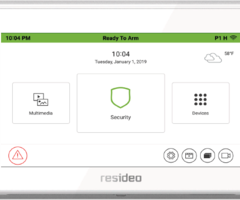
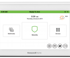
TUXEDO
W
Home
Automation and
Security System
Quick Installation Guide
Full Installation Guide [Part Number 800-
25176] available online at:
https://mywebtech.honeywellhome.com
Select
the
icon to access the Introduction and T
raining Videos.
To reset the Touchscreen, press and hold the side Power Button for 3 seconds and
then
press on the
“Press here to Reset” message
on the screen to start the reset function.
The Touchscreen can also be
reset by pressing and holding the rese
t button for
approximately
15 seconds
until the touchscreen resets automatically
.
TOUCHSCREEN
INITIALIZATION
When initially powered, the boot sequence starts and is followed by six setup steps.
1. Operation Mode Selection:
Select
Normal Mode
,
Safe Mode
,
Dem
o Mode
,
or
Automation
Mode
to turn the option on or off.
2. Set ECP Address/RIS Automation Address:
If using one Touchscreen, leave the address set to 1
and select
Apply
. If using more than one, power
-
up each Touchscreen one at a time, and set each
Touchscreen address to one of the addresses enabled in the control panel.
If using Remote
Services, set the RIS Automation Address to the appropriate RIS address used for Total Connect
2.0.
3. Honeywell Home End User License Agreement:
Review and accept the agreement.
4. Network (Wi
-Fi) Setup:
Select the Wi
-Fi network and enter the passphrase/shared key or touch
Skip Setup and Remind in 2 hrs
.
5. Important Operation Information:
Enter the User’s Name, Tuxedo Name, Region, Mobile No., Zip
Code and Email Id.
6. Remote Login:
enter the User name and password for local access through a web browser.
SYSTEM INFORMATION &
UPGRADES
To view the current software version installed, Interface name and MAC Address
, select
Set
up
→
System
Info
.
Software upgrades may be availabl
e. Check the box that says “Enable Remote Upgrade” for over the
air (OTA)
updates
(re
quires network connection)
.
OTA is initiated by A
larmNet
360.
When the OTA screen appears on the T
UXED
OW,
the user can
accept, reject or postpone the download process.
If
accepted
, the download process
starts,
and a
message is shown in the upper
left
corner of the screen.
If
rejected
the process never starts.
If
postponed
a dialog box will show in the upper left showing the user to click the box to start the
download process.
After download is completed the user must then accept, reject or postpone the download from being
installed.
Reject and postpone are the same as above.
If accept is pressed the
TUXEDOW
starts the
updating process
; once done the TUXEDOW
reset
s.
ECP ADDRESS
If the screen is displaying “ECP Error
,” the address is not valid for the
control it is connected to, the
ECP address in the
Touchscreen
is not valid for the panel that it is connected to. In this case, to
change the ECP Address, enter the default code of “4140” to advance to the next screen.
Note:
Default code “4140” is the T
UXEDOW
default installer code before connecting to a control panel.
Once connected to a control panel, use that panel’s installer code.
1.
Select
Set
up
→
System Setup
→
CS Setup
.
2. Enter an Authorized Code, if required.
3. Select
ECP Address
; enter an ECP Address. Available ECP Addresses are:
1-2, 5-
6 ..............
for residential controls
1-30
...................
for commercial controls; supports 6 AUIs.
4. Select the
Back
arrow to return to the previous screen. Select
to save changes.
DISARMING THE SYSTEM AND SILENCING ALARMS
To silence Alarms or Trouble conditions:
enter your 4-
digit user code,
select
the
Clear
button,
then enter your 4-
digit user code again.
To te
st the Alarm,
select the
Security
and
More Choices
icons.
- Select
Console Mode
and refer to the Control Panel User Guide for procedure.
DISPLAY & AUDIO SETUP
1.
Select
Set
up
; slide the
Brightness / Volume
bar
to adjust
settings.
2.
Select
Set
up
→
Disp & Audio Setup
; enter an Authorized Code.
- To adjust the screen timeouts, select a time interval from the drop-
down list for each option
(Backlight Off After, To Homepage After, Auto Slideshow After
, and Temperature Unit
.)
- Select
Chime
,
Voice
or
Voice Chime
operating mode.
- To clean the
Touchscreen
screen,
select
the
Clean Screen
icon;
select
Continue
, or
select
Cancel
to exit.
- Select
to save changes.
Select
the
Back
arrow
to return to the previous screen.
USER SETUP
1.
Select
Set
up
→
Sys
tem Setup
→
User Setup
.
2.
Select
and enter
a User name and enter an
Authorized Code
for this user.
Select each field
and enter the appropriate information.
3.
Select
to s
ave
the user information or
select
Back
arrow to return to the previous screen.
For available user numbers, see control panel instructions.
TIME
& DATE
1.
Select
Set
up
→
System Setup
→
Time/Date Setup
.
2. Enter an “Authorized Code”.
a) If
Get Time
is
select
ed,
the
Touchscreen
downloads the time/date from the control panel and
exits the “Set Time” screen. (The Get Time icon appears with residential panels and may not
appear with all commercial panels.)
b) Or, set the time/date from the
Set Time/Date
screen.
Use the slide bar to scroll and select each
value.
3.
Sele
ct
to save: A message displays
“Time Setting Confirmation”
, select
Yes
or
No
.
SCREEN SECURITY
See the full Installation Guide for user Authority Levels.
1.
Select
Setup
→
System Setup
→
CS Setup
.
2. Enter an Authorized Code;
select
the
Screen Security
icon
.
- To make changes, select the line to change and the level of user to have access, and then
select
to save changes
.
CODE AUTHORITY
1.
Select
Setup
→
Sys
tem Setup
→
CS Setup
.
2.
Select
Code Authority
.
3. Enter the 4-
digit Code for the user you want to obtain authority level information about.
PANEL CONFIGURATION
1.
Select
Setup
→
System Setup
→
CS Setup
.
2. Enter an Authorized Code and
select
Panel Config
. Select
to clear the Touchscreen
and reload the panel configuration into the Touchscreen.
NIGHT SETUP
(If the control panel supports if)
The NIGHT function can be set to arm the system in one of five arming modes. To change the arming
mode;
1.
Select
Setup →System Setup → Advanced Setup
.
2. Enter an Authorized Code.
3.
Select
Night Setup
; select desired mode:
Away
-
Stay
-
Instant
(default)
-
Night
(Residential Panel Only) –
Maximum
.
4.
Select
to
save changes.
EMERGENCY MESSAGES
1. Select
the
PANIC
Icon. Press and hold (for at least 2 sec
onds) the associated alarm icon (
FIRE,
POLICE
or
MEDICAL
).
MULTIMEDIA
NOTE:
Micro
SD
card max size is 64GB and must be FAT32, SDXC format.
Recommended is Kingston or
Samsung.
Picture Setup
:
Insert media card (Micro
SD/SDHC) with stored (.bmp
, jpg
, png
or .jp
eg) photos.
1. Select
the
Multimedia
and
Picture
icon
s and then select
a
Picture
folder to view.
2. Select a photo and
select
Play
to view pictures in a slide show format.
3. To set a picture as wallpaper,
sel
ect the
Default/Wallpaper
folder to activate.
4. Select
the
Picture Info
icon
to view picture information.
Video Setup:
Insert media card
(Micro
SD/SDHC)
with stored video files
. Supported video
playback
formats are (avi, .ts, .mpg, .mp4, .mov, .mkv,
or .flv).
1. Select
the
Multimedia
and Video
icons
and then select the
Video
folder to view.
2. Select
Play
to start the selected video file.
3. Select
the
Video Info
icon to view video information.
Camera Setup
:
See the full installati
on Guide for further information.
•
If using existing (mounted) cameras;
go to Step 4.
•
For
first time setup,
scan/configure the cameras prior to mounting, and do the following:
1. Connect an Ethernet cable to the back of the camera (LAN); connect the oppos
ite end to the Ethernet
Port on the router.
Follow th
e camera
’s installation instruction
s.
2. Apply power to the camera; wait for initial power
-up.
3. Select
Camera
.
4. Select
Ca
mera Discovery
to locate the camera. The screen displays:
“
Disco
vering Cameras
...”
5. Select
the
Add
icon if
the camera information is not automatically located, to enter information manually.
6. To edit camera information, highlight
the camera name and
select
the
Edit
icon
. Enter required information
and then select
the
Save
icon.
a) To retrieve camera settings and connect to the camera, select
the
Connect
icon.
b)
Select
TOTALCONN
icon
to reset the camera for remote viewing
and activate a Total Connect account.
c) Select
Reset
to reset the camera to factory default. Select
Yes
or
No
.
7. When all cameras have been added, select
Wireless Settings
and enter the wireless information from
the router.
8. Select
Apply to All
to set cameras to wireless operation and control the Security System, local Z
-Wave
devices and view local cameras from your browser. If the camera does not have wireless capability,
leave the camera connected to the router.
Use the icons to:
Delete
→
Play
→
Stop
→
Refresh
→
Auto Pan
→
Full View
→
Pan/Tilt
→
Back
.
Wi
-Fi
SETUP
& WE
B BRO
WS
ER
The TUXEDOW Keypads IP Address is used on a standard web browser to control user functions such as
Security, Z
-Wave operation, and camera viewing.
See Full Installation Guide fo
r supported browsers.
NOTE:
Supports 2.4GHz and 5GHz frequencies
1.
To connect to a
Wi
-Fi network
, select
Setup
→System WIFI
and select a Wi
-Fi network from
the list to connect to. Or, select
to add a new Network connection. Enter the new
Network nam
e
SSID No
. and
Security
type; then select
Connect
.
2. Select
the
Setup
and
System
Info
icons; the IP Address is displayed on the System Information
Screen. Enter the IP Address on the keypad into a PC, Smart Phone or Tablet Browser.
3. For
Remote Access
, select
the
Account
icon
to create a browser log
-on page for each user (for
higher security) when viewing from a web enabled device or PC on a different sub
-net.
Enter the
required information for each field
.
AUTOMATION
- DEVICES
If using two keypads, see
Full installation Guide section “
Secondary Keypad
” (Controller
).
Include
a Z
-Wave Light,
Switch, or Outlet Module:
1. Install device according to the manufacturer’s instructions.
2. Select
Devices
→
Setup
→
ADD DEVICE
.
3. Select
the
Function Key
on the device; follow the keypad’s on
-screen messages until
“Device added
successfully”
.
Include
a Door Lock:
1. Assemble the Z
-Wave door lock according to the manufacturer’s instructions.
Be sure the door lock orientation/handedness is correct.
2. Refer to Door Lock’s Instruction Guide and connect necessary cables, then install batteries.
3. Add
the door lock within 5 feet of the keypad; refer to the Door Lock’s Instruction Guide
for procedure
.
NOTE:
Program
a 4
-digit user code in the control panel prior to programming that user code into the door
lock.
4. Select
Devices
→
Setup
ADD DEVICE
.
5. Program the selected user code from the panel.
Include
a Resideo
Z-Wave
Thermostat:
1. Install thermostat according to the manufacture
r’s instructions.
Inclusion
procedure may vary. Refer
to
the Thermostat instructions.
2. On the Honeywell thermostat select
Thermostat
; set the “Time/Date” and follow the instructions in the
thermostat Installation Guide for
including into the network
.
3. To complete, select
Done
.
4. Select
Exit
to return t
o normal operation.
5. To verify activation: on the T
UXEDOW
Keypad,
select
Back
; wait 30 seconds.
Select
Refresh
; the new
device is
displayed. See
Installation Guide to Exclude
/Edit/Abort Z
-Wave devices.
Include a Resideo
Wi
-Fi
Thermostat
1. Select
Devices
→
Thermostat
.
2. Enter the
Tota
l Connect Comfort
Account User Name, and Password
.
Defaulting the Z-
Wave Controller
1. Select
Devices
→
Setup
→
MORE
→
Z-WAVE DEFAULT
2. Press
Yes
to default the Z
-Wave controller or
No
to cancel.
NOTE:
Please use this procedure only when the network primary controller is missing or otherwise
inoperable.
SCENE SETUP
The Scene feature is used to control a
single device, or multiple devices based on pre
-set “Conditions,”
“Triggers,” and “Actions.” When a trigger/condition occurs, the defined action is executed.
1. Select
Devices
→
Scene
→
Add
.
2. Select
Users Scene
; enter a SCENE NAME
and
select
OK
.
3.
Add
the “Condition,” “Trigger,” and “Action” that you want to occur for this Scene.
4.
After each selection
select
Save !!
Note
: Determine if you need a Condition. The Condition is a ‘condition’ set to occur prior to a trigger event.
See example below.
Example
: Turn the lights on when the system disarms, but only at night.
(Condition)
... “only at Night”
....Set the
TIME
Condition (enter the
Start/Stop
Time
and
Days
).
(Trigger)
... when the “system Disarms”
...Set the Trigger to
SECURITY:
System
Disarm
(Action)
...Turn the “lights ON”
... Set the Action to
LIGHT:
ON
.
Scene Rules
•
Triggers
& Conditions
include: Time, Security
, Thermostat
, Door
, Garage Door, Water Valve
.
•
Actions include: Security, Lights On/Off, Thermostat, Door
, Garage Door and Water Valve.
•
Ea
ch Trigger event can have up to 3 Actions.
•
A Trigger event and Condition cannot be the same (i.e., if setting a Trigger event for SECURITY, you
cannot set a SECURITY Condition).
Panel Faults –
If
Panel Fault icons are displayed on the Security screen
see the full Installation Guide.
AC Loss
Bell Failure
Expander Failure
Low Battery
LRR Supervision Failure
Max Attempts
Exceeded
Pager Failure
Telco-
1 Cut
Telco-
2 Cut
Wireless Failure
Panic
MOUNTING
OPERATING THE TOUCHSC
REEN
For operating instructions, see the User Guide for the control
panel used with this Touchscreen.
NOTE:
If the touchpad is defaulted, it will cause the Z
-Wave
module to default.
This
T
UXEDOW
Touchscreen
is for indoor use only and should be mounted at
a comfortable viewing level. Avoid
mounting in areas of high condensation such as bathrooms or in locations where bright light or sunlight shines directly
on the screen. The Touch
screen
is surface mounted directly to a wall.
Locate the mounting plate and attach to a wall using the 4 screws provided.
Insert
bottom side of Touchscreen over
the mounting plate and then click in top side
to
snap into place. Install the
cover securing screw
at the bottom of the
device to secure.
The bottom securing screw must be
installed.
To remove the
Touchscreen from its mounting location, i
nsert
the end of a
screwdriver
between the plate and the
touchscreen and twist to loosen and pull out to remove.
WIRING
CONNECT WIRING
Route wiring from the controller through the openi
ng in the
mounting plate.
Connect the Touchscreen in parallel with Touchscreens and
other peripheral devices using the Touchscreen data (ECP)
bus. If more than one Touchscreen is wired to one run, then
the maximum lengths must be divided by the number of
devices on the run. (e.g., the maximum length is 75 feet if two
devices are wired on a #22 gauge run).
Wire Gauge
Length
#22 gauge
150 feet
#20 gauge
240 feet
#18 gauge
350 feet
#16 gauge
550 feet
Refer to the control panel Installation Guide for a
dditional
Information.
NOTE
: If mounting on a surface where the wire can not be
inserted through the hole in the
mounting bracket
,
knockouts have been provided to run the wires through the
sides
. They are on all four sides.
To knock them out, before
mounting
flip over the mounting plate and, using a pair of
pliers, remove the plastic to make room for the wire.
This equipment should be installed in accordance with
National Electrical Code, NFPA 70, Standard for the
Installation of Residential Fire Warning Systems, CAN/ULC-
S540 and Chapter 2 of the National Fire Alarm Code,
ANSI/NFPA 72 (National Fire Protection Association,
Batterymarch Park, Quincy, MA 02269). Printed information
describing proper installation, operation, testing,
maintenance, evacuati
on planning, and repair service is to
be provided with this equipment.
SPECIFICATIONS
Mechanical Specifications:
Width: 7.91 inches (200.9mm)
Height: 5.04 inches (128.016mm)
Depth: .827 inches (21.00mm)
Electrical specification:
Backlight ON, Soun
d ON
12V, 270mA
Operating Environment:
Humidity: 93% RH, non
-
condensing
Operating Temp.
14°F to 131°F /
-
10°C to 55°C
(UL tested 32°
-
120°F / 0° to 49°C)
Ship/Storage/Temp.: 40°F to 158°F /
-
40°C to 70°C
Z
-
Wave
:
Z
-
Wave Plus Controller
Install in ac
cordance with NFPA
-70 and NFPA
-72.
Compatibility
The table below identifies the alarm systems that the Touchscreen can
interface with, the maximum number of Touchscreens that can be used
with each system, and the minimum alarm panel software revision level
for compatibility.
Panel Type
Panel Version
Max # of
touchscreens
VISTA-
15p
V3 and higher
2
VISTA-
20p
V3 and higher
4
VISTA-
21iP
All
4
VISTA-
128BPT
All
6
VISTA-
250BPT
All
6
VISTA-
32FBPT
All
6
VISTA-
128FBPT
All
6
VISTA-
250FBPT
All
6
UL Note:
For
residential burglar alarm applications, the entry delay
time shall not exceed 15 seconds, therefore use is restricted to
compatible listed control units capable of being programmed for this
time parameter.
Warning:
5G Band 5150-
5250 MHz is only for indoor use.
Warning
: Owner’s instruction notice: ’Not to be removed by anyone
except occupant’
This system must be checked by a qualified technician at least once
every three (3) years.
U
L
Use a UL Listed, battery
-
backed supply for UL installations. The battery supplies power to these keypads in case of
AC power loss. The battery
-backed power supply should have enough power to supply the keypads with the UL
required minimum standby power t
ime.
IMPORTANT:
Touchscreens powered from supplies that do not have a backup battery do not function if AC power is
lost. Make sure to power at least one keypad in each partition from the control’s auxiliary power output or UL Listed
battery backed up pow
er supply.
FEDERAL COMMUNICATIONS COMMISSION & ISED CANADA STATEMENTS
The user shall not make any changes or modifications to the equipment unless authorized by the Installation Instructions or U
ser's Manual. Unauthorized changes or
modifications could v
oid the user's authority to operate the equipment.
CLASS B DIGITAL DEVICE STATEMENT
This equipment has been tested to FCC requirements and has been found acceptable for use. The FCC requires the following stat
ement for your information.
This equipment generates and uses radio frequency energy and if not installed and used properly, that is, in strict accordance with the manufact
urer's instructions, may
cause interference to radio and television reception. It has been type tested and found to comply with the
limits for a Class B computing device in accordance with the
specifications in Part 15 of FCC Rules, which are designed to provide reasonable protection against such interference in a residential installation. However, there is no
guarantee that interference will not occur in a particular installation. If this equipment does cause interference to radio or television reception, which can be determined by
turning the equipment off and on, the user is encouraged to try to correct the interference by one or more of the following measures:
• If using an indoor antenna, have a quality outdoor antenna installed.
• Reorient the receiving antenna until interference is reduced or eliminated.
• Move the radio or television receiver away from the receiver/control panel
.
• Move the antenna leads away from any wire runs to the receiver/control panel.
• Plug the receiver/control panel into a different outlet so that it and the radio or television receiver are on different branch circuits.
• Consult the dealer or an experie
nced radio/TV technician for help.
ISED CLASS B STATEMENT
This Class B digital apparatus complies with Canadian ICES
-003.
Cet appareil numérique de la classe B est conforme à la norme NMB
-003 du Canada.
FCC / ISED STATEMENT
This device complies with Part 15 of the FCC Rules, and ISED’s license-
exempt RSSs. Operation is subject to the following two conditions: (1) This device may not
cause harmful interference (2) This device must accept any interference received, including interference that may cause undes
ired operation.
Cet appareil est conforme à la partie 15 des règles de la FCC et exempt de licence RSS d’ISED. Son fonctionnement est soumis aux conditions suivantes: (1) Cet
appareil ne doit pas causer d' interférences nuisibles. (2) Cet appareil doit accepter toute interférence reçue y compris les interférences causant une réception
indésirable.
Responsible Party / Issuer of Supplier’s Declaration of Conformity: Ademco Inc., a subsidiary of Resideo Technologies, Inc., 2 Corporate Center Drive., Melville, N
Y
11747, Ph: 516-
577
-2000
Partie responsable / Émetteur de la déclaration de conformité du fournisseur :
Ademco Inc., une filiale de Resideo Technologies, Inc., 2 Corporate Center Drive.,
Melville, NY 11747, Tél. 516
577
-2000
Wi
-Fi
®
and the Wi
-Fi logo are
registered trademarks of Wi
-Fi Alliance.
SUPPORT
, WARRANTY
& PATENT INFORMATION
For the latest warranty information, please go to:
https://www.security.honeywellhome.com/warranty
For patent i
nformation, see https://www.resideo.com/patent
SUPPORT:
For technical support, call 1-800
-645-
7492 M
-F 8:30am to 5pm EST
REFER TO INSTALLATION INSTRUCTIONS FOR THE CONTROL PANEL WITH WHICH THIS DEVICE IS
USED
FOR WARRANTY INFORMATION AND LIMITATIONS OF THE ENTIRE ALARM SYSTEM.
The product should not be disposed of with other household waste. Check for the nearest authorized collection
centers or authorized recyclers. The correct disposal of end-
of-life equip
ment will help prevent potential negative
consequences for the environment and human health.
Ê800-25178BÇŠ
800
-
2
5178
B
4
/
1
9
Rev
B
2 Corporate Center Drive, Suite 100
P.O. Box 9040
Melville
, N
ew
York
11747
© 2019
Resideo Technologies, Inc
www.resideo.com
This product manufactured by Resideo and its affiliates.
The Honeywell Home Trademark is used under license from
Honeywell International Inc.
- Uploaded