Alarm Grid LYNX-EXT: Constructing the LYNX-EXT Kit
Related Products
Related Categories
Description
Alarm Grid LYNX-EXT: http://alrm.gd/lynx-ext
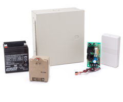
Sterling wires all the non-siren parts for the LYNX-EXT. This wiring is the first step in getting this kit up and running. Once these connections are made, moving adding any of the wired sirens that you want is a simple task.
Transcript
So, now that we've explained the tools that we have, and the parts needed, we're gonna show you how to put this all together because it can be a little tricky. Okay, first thing we're gonna do, is cut a length of wire here. Strip it down, so we're just removing the insulated sheath on this wire. When we say we are using four conductor wire, what that means is, inside the insulating sheath, we have four different internal wires, four conductors. In this case we have; black, red, white and green. A lot of times you'll see yellow and green also but, these are the four conductors that we'll need and we're gonna strip the other end as well. They also make two conductor wire, if for instance you're doing your connection from the transformer to the power supply, that's only a two conductor connection. So you can certainly use this four conductor trim down two conductors and just use two for the connection. Some of our connections that we're gonna be doing, is a four wire connection as well, we just so happened to use the four wire connection here. We're gonna first start with the 5800RL okay?, to show you the wireless setup. This does, come included with a nice little instruction guide that shows you the wiring here in this diagram and on the back, talks about the house ID codes, so you can see how to set your DIP switches, which are are the bottom right of the relay module. These DIP switch assignments, will tell the relay module, the house ID code of your control panel and that's how it ties the system to this setup. So that if your neighbor has a similar setup, the thought is they're gonna have a separate house ID code, their alarm going off will not trigger your alarm. That's what the house ID does. So, now we're gonna get down to the connections. Before we do any kind of power from the wall, we want to make the rest of our connections first, so we're gonna from our relay module, and then connect to our power supply. So we have our relay module, there is a strip of screw terminals on the left. Okay, there's eight of them and it's two separate relays normally close, normally open and a common is the top six terminals. So normally open or normally close, normally open-common and then again normally close, normally open-common and then you have your AC or DC inputs, okay, positive and negative. Positive on the top, negative on the bottom. The reason this has two separate relays, is that not only can it drive the siren or sound or strobe when the alarm kicks into alarm mode, it can also be used with an LED to indicate if the system is armed or disarmed, okay?. The relay A will show you the alarm condition; burglary alarm or fire alarm when the siren kicks on. Relay B, the bottom relay will tell you whether the system armed or disarmed. What we're gonna be dealing with is relay A. So, we have our wire cut, and we're gonna connect our relay module to our power supply. So we're gonna need a two conductor connection from our DC input on our relay coming off of our DC output on our power supply. We're gonna use red and black here. So we're gonna strip the end here, using our wire strippers to get our exposed wiring and always, you should be using red for positive, black for negative, just to keep a normal convention. Twist them down, okay? You really don't need much copper showing so if like I did, I just cut a little bit more than I needed, I'm just gonna trim these ends okay, now we have a nice clean wire. I twisted them down because this is stranded wire. So, now we're gonna make our connections from our power supply to our relay module. Turns out, our relay module actually requires a flat head screwdriver so I'm just gonna reach into my toolbox so we actually will use a Phillips head and a flat head in this installation. So this terminal strip, and just like most terminal screws that we work with, we just need to loosen up the screws enough so that these holes are opened up then we use these holes, to connect our power. Terminal seven counting from the top to the bottom, terminal seven is positive. So we're gonna land our red wire, to that terminal, screw it down nice and tight. You pretty much want to go as tight as it can so that if you give a nice firm tug on the wire, it's not gonna come out. And then directly below that, terminal eight the last screw we're gonna use our black wire which is negative DC. That's the DC input, coming off of the DC output of the power supply. So these are now connected, we have a nice connection, and you'll notice with this cover of the relay module, the wiring comes out the side nice and clean so you don't have to worry about fishing through the back or anything like this. This module is very light, it can be mounted with double-sided tape, or you can used screw holes if you'd like. But with the size and the weight, we normally recommend to just go ahead and use the double-sided tape. So now that we're connected here, we're gonna strip off the green and the white conductors which we're not using, okay? Keep it clean. Now, on the other end, we have to connect our black and our red to our power supply. So again, we're gonna strip off a little bit of the end here. And we're gonna twist them down, we're using stranded wire so we have multiple strands, stranded is nice so that, if one of your wires gets nicked, the idea is you have multiple other strands to keep the connection nice and tight. So just to make your life a little easier, when you're making your connections if you twist them, with your fingers, it makes a nice little tight connection. Again, we're gonna trim it down, once we've twisted it so that just a little bit is exposed and showing and then these get connected to our DC output. You'll notice on the AD12612, all of the terminals are labelled. We have two AC terminals, polarity is not relevant with AC, so it's just AC and AC but for DC, you need to make sure you observe, polarity. So positive is all the way to the right, negative is to the left, red to positive, black to negative. We're gonna to make those connections now. This one uses a Phillips head screwdriver, we have both, so we're just gonna loosen this up a bit. And our wire just sits underneath the screw. Tighten it down. And we got our negative, our black wire. Tighten that down, give a nice little tug, make sure they are tight. Trim off our extra wiring on the green and the white. And we are now connected, for our power supply to our relay module, okay?. So we have our DC output going to our DC input on our relay. The next thing we need to do, we're gonna need a little jumper wire okay, from one of the terminals on the relay to another terminal on the relay. Actually, this conductor that we just trimmed down, we're just gonna grab this, and trim off a little end here. Because this is a little jumper inside of the relay, this wire does not need to be long at all. It's gonna be living right inside of the relay module, so that's why we can use this little piece that we had just trimmed back from our other connection. A little harder to use this wire on the length of it but just have to strip down the end of it to get enough exposed wire. Okay. Now again, twist the end so our strands aren't getting messed up as we connect them. And you can see on the diagram here, that we're connecting terminal two, down to terminal eight which is a shared terminal for the DC negative, so we're just going from two to eight. We're gonna loosen two up laying the wire in, and screw it down nice and tight and then we're gonna loosen up our black wire, which is terminal eight. And our jumper fits in, there's plenty of room to lay in two wires there. Screw that down and then you can just kinda tuck your jumper up so that the cover will be able to close. So now we've made our connection between two and eight, okay. This is tying the relay into the DC power. A very important connection, will not work without that connection. So, we have now made the proper connections between the relay and the power supply and the last little bit that we need is our siren.
- Uploaded
- Duration: