Honeywell 5800C2W: Connecting a Wired Contact to a Zone
Related Products
Related Categories
Description
Honeywell 5800C2W: http://alrm.gd/honeywell-5800c2w
Honeywell 945T: http://alrm.gd/honeywell-945t
Get Monitored! http://alrm.gd/get-monitored
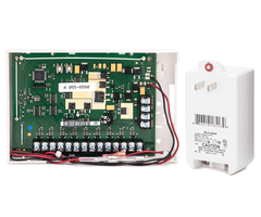
Sterling connects a Honeywell 945T wired terminal sensor to the Honeywell 5800C2W. The process is surprisingly simple, though you'll definitely be more comfortable getting a quick look at how to connect the switch to the transmitter using the included resister.
Transcript
To demonstrate how the unit works we have a Honeywell 945T which is a simple wired contact read switch and magnet. We're going to connect this to our C2W and learn it into our LYNX Touch as a wireless zone. We're going to show you how that's done.
Okay. To make our connections we have some B wire connectors. These are called dolphin connectors, beanie connectors, B connectors, a lot of different names for these. All they really are is a little capsule with some insulated gel on the inside so you can stick two wires down, crimp it shut with your wire splicer. It makes a nice, tight connection. You have no corrosion with the little gel on the inside.
We've got a little Phillips head screwdriver, we have our wire splicers and crimpers, and we're ready to go. We also do have a battery backup as the C2W zones are powered from a transformer. They should also have a battery backup so that your zones will work with a power outage.
The first thing we're going to do is open this little guy up. You basically stick your fingers into the gaps. There's a gap along here and along here, and you just kind of pry the cover up and away. There is no tamper switch or anything that you have to pop. It really does just snap open.
On the inside here, this wire with this fuse is our battery connection going to our backup battery. We kind of just uncurl that wire. If you're going to do a conversion from an old control panel your control panel most often will have one of these sealed lead acid batteries inside the control panel. You could leave the control panel powered up.
You're going to take all your zone wiring off of your old board and land it to this, then you would just connect your battery here. Okay. Now you have your battery connection and you can mount this under your control panel. For this purpose we're just going to show you here on the table.
Some things to point out, first of all, we have this sticker here. It says A0258050. This, if you've ever done any Honeywell wireless programming, will be very familiar to you. It's the seven digit serial number. There are nine available zones on this unit. It'll start 8051 and advance up a digit 8052, 3, 4, 5, and so on up to 8059 if you're going to use all nine zones. This strip of screw terminals on the side we have ground and 15.5 volts in. That's going to be used to connect our transformer wiring to our 5800C2W.
Then, we also have a 12 volt aux and a ground. If you're connecting anything other than door contacts, if you're connecting motion detectors or glass break detectors, devices that require four wires, two for data, two for power, you need power. Most control panel boards have an auxiliary power output. When you hook up a motion detector you connect two of the wires to the zone wiring. You connect the other two wires to the aux power of the panel.
Now that we're going to be taking all our zones off of our old panel and connecting to up here, if you're going to do a motion or a glass break you use these two terminals - 12 volt aux and ground - and those two terminals will provide you the power needed to power your motions and your glass breaks. It's a very handy little device. A lot of converter units out there on the market from other companies do not have that auxiliary power, so you can't really use any four wire devices.
One thing to note is that we do not recommend using this with smoke detectors. If you had old hard wired smokes, I recommend you replace them with new wireless smokes. Do not connect smoke detectors or heat sensors to this device. You'll see on the front cover you have a nice handy explanation of each terminal, each LED, and then the switches on the top.
Now, we're going to show you how to use this device. What we're going to use is we have a little jumper wire. This jumper wire is 22 gauge wire, very similar to most wiring you'll see on every alarm system you're dealing with, so when you're doing your conversion from wired to wireless you'll see a lot of wiring like this. It's 22 gauge. That's the thickness of the wire, and this is a two conductor wire, so you have your black and your red connections.
What we're going to do first is connect this to our 945T contact. A 945T, all it is is a mercury read switch inside of this unit. You have a matching magnet. When the door or the window is closed, the magnet is in line with the sensor and the zone is happy. If the door or window opens, the magnet is pulled away, the sensor is faulted, and the zone is triggered for an alarm.
We're going to use this as our demonstration of a wired zone. We take our flat head screwdriver and we connect our zone wiring. All we're doing is very simple connection. We're plugging in one wire into one screw terminal and screwing it down tight. We're taking our other wire to the other opening screw. Screw it down tight. Now we have our wired contact connected. We can set this aside for a minute.
On the other end we need to connect to any of the zone terminals along the bottom. We have a Z1 and a ground, a Z2, a Z3 and a ground, a Z4, a Z5 and a ground, a Z6, a Z7 and a ground, a Z8, a Z9 and a ground. You'll notice each set of zones share a ground. Zones one and zone two share a ground. Zones three and four share a ground. Zones five and six share a ground. Zones seven and eight share a ground. Zone 9 gets its own ground.
Most wired panels are eight zone panels, so as long as your old panel doesn't have an expansion board one 5800C2W should be all you need to convert your old wired system to a wireless system. If you need additional zones you can use additional 5800C2Ws.
We're going to connect to zone one. When we make our connection from our zone to our 5800C2W a resistor will need to be used. Most control panels use resistors. You may come across yours doesn't have a resistor. If it's not at the control panel the resistors might also be out in the field. It can be very hard to find those resistors, and it can be hard to know the value of those resistors.
The beauty of this little module is that it has a button that will auto calibrate and determine the specific resistor value of any zone connected to it so that you don't have to replace all your resistors. It's a very nice little feature that Honeywell added. Your resistor values do need to be between 1K and 10K, but as far as I know I don't know any system that would use a resistor outside of those values.
For our demonstration we're not converting an actual zone over. We're just adding a zone, therefore we need to add a resistor. It does not work if there's no resistor added. We get a strip of eight resistors with every 5800C2W, because Honeywell doesn't know if you're converting something over or you're dealing with raw wiring with no resistors.
A resistor looks like a little diode with two wires on either end. We're going to run our resistor in series with one of our zone wires. We're just going to wrap the wire around the resistor leg. We're going to stick it into our little B connector. We shove it up into there. It makes a nice solid connection, and then with our wire strippers at the end there's a little crimping tool. You just press down all the way down the body of the B connector. This establishes a nice tight connection between our resistor and our zone. You'll see these in a lot of panels, nice professional installation there.
Now, we have our two legs to land to our zone. We're going to land one side to the ground which is one side of zone one. Then, we're going to take our resistor and wire it in to Z1. Now we have our zone with our magnet wired to our converter unit. All right. With that we are ready to connect our transformer. We have another strip of wiring here, and we have pre-stripped it. This transformer you do need to observe polarity. We have a plus terminal and a negative terminal. We're going to use the plus terminal for our red positive wire. We're going to screw it down nice and tight. We're going to use our black wire for our negative terminal.
We're just fish hooking those wires around each terminal, screwing it down tight so when you tug on it nothing's coming loose. This will get plugged into our wall outlet. The other end we're going to land our positive red wire to our 15.5 volt end terminal conveniently labeled for you so you know exactly what you're connecting. We're connecting our 15.5 volt positive wire and we're connecting our negative ground wire. Okay. Those wires are in there nice and tight.
Now we are ready to power up. We plug our transformer in and we'll see some lights pop on on the board. These indicator LEDs show you whether or not the zones are calibrated with the top light. If they were not calibrated this would not be green. It would be red, and then you could press the calibration switch and it would auto calibrate the resistor value. Because we used the resistor that came with the unit there was no calibration needed.
This green light indicates AC power. It's green, letting us know that we've properly connected our power. This third light is yellow, indicating a low battery. We have yet to connect our battery which is why it's showing that. We have purposely left that off to show you something on the panel in a second.
Then, finally the blinking light is a data transfer if this unit was trying to send a signal. If you notice, it'll flash when I fault the device. It's trying to tell some sort of control panel, whatever it's connected to, that something's going on. All right. Those are the LEDs. These switches, this switch on the right is not used. Switch SW2 is the one for the calibration.
This wire along the top and the side is the wireless antenna. This unit has a greater range than most wireless sensors because they understand your control panel may be far away from your devices in your house. This has a 300 foot range. Typically, Honeywell devices have a 200 foot range, so Honeywell built a stronger transmitter into here so that it will get back to your panel better.
There is a little mercury read switch on the right. When the cover is on you have this little plastic piece with a magnet. What you do for that is you can see there are two little tabs that fit into two little notches, and then you snap it down into place so that when the cover's on properly the magnet is in line with the read switch. That's for the cover tamper.
- Uploaded
- Duration: