Honeywell iGSMV4G, GSMV4G, 7847i Wiring Instructional
Related Products
Related Categories
Description
Upgrading your existing alarm system to the Honeywell iGSMV4G will provide you with increased functionality and reliability compared to traditional analog phone systems. This video from alarm grid outlines the process of installing this new hardware to upgrade your alarm system. While the iGSMV4G is the product featured, the wiring process is also the same for the Honeywell 7847I.
Chances are, if your home security system was installed by a Honeywell dealer, then it’s the VISTA 20p; Honeywell’s flagship security system. This system only supports traditional phone line communication with the alarm monitoring service.
Analog phone service is being phased out in favor of a digital signal. These digital signals present a myriad of problems for alarm systems that can result in problems communicating with the alarm monitoring service, which can be an especially scary situation in the event of a break in. By upgrading to a communications system that uses either internet, cellular or both networks to communicate with alarm monitoring, you’ll no longer be exposed to potential issues that plague digital phone service and alarm systems.
Sterling at Alarm Grid explains how you can also upgrade your system to allow for Total Connect 2.0 service at this time as well. Total Connect 2.0 allows you to add many convenient services to your alarm system, like the ability to control aspects of your system with a computer or mobile device. There are several Alarm Grid videos available that provide further detail on upgrading your system’s PROM chip to enable the ability to use Total Connect 2.0.
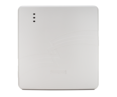
Before beginning the wiring process, the video explains the different tools you’ll need to complete the upgrade. You’ll need the IGSMV4G with its transformer and battery backup, and your alarm control panel. You’ll also need a pair of wire strippers a small screwdriver for the terminal screws, and some four conductor wire. In this video, Sterling uses 22 gauge four conductor wire.
Both the Honeywell VISTA 20p and the iGSMV4G require power from the wall. For many people, this may present a problem. Because the transformers associated with these systems are so bulky, there may not be room on the wall outlet to plug in both transformers. If you find that to be the case, and there isn’t another viable outlet for you to use, you’ll be able to use the transformer for the iGSMV4G to power both the iGSMV4G and the alarm system itself. The steps for using the single transformer to power both units is described in the video.
Sterling then goes on to walk you through the simple wiring you’ll need to complete to provide the iGSMV4G with the power and data connections necessary for use. Once you’ve completed the wiring for power and data, Sterling then details the proper wiring connections you’ll need to make to connect the unit to the transformer.
Once you’ve completed the wiring for system power, transformer power, and data transmission, Sterling explains that you must reconnect backup battery power to the iGSMV4G as well as battery backup power to your alarm control panel.
Once you’ve done that, you’re ready to seal both units back up, remount them and plug your transformer(s) back into wall power. Once you’ve completed these steps, you’ll have an alarm system that’s capable of cellular, internet or dual path monitoring with either Total Connect 2.0 or central monitoring service.
Transcript
[SOUND EFFECT PLAYING] Hi, DIY-ers. Sterling, with Alarm Grade here. And today we're going to show you how to wire up an iGSMV4G 4G dual path Honeywell AlarmNet Communicator to a VISTA-20P Honeywell wired alarm control panel.
On its own, the VISTA-20P, which is Honeywell's flagship panel, by far the most popular panel that Honeywell dealers will install for you, it will only support phone line communication using the incoming phone terminals, using a traditional analog phone line.
This system is not designed for digital phone service. And all phone companies are transitioning away from analog phones and going to digital phones, if it's not done already. Even if you have a true copper analog phone line in your house the chance that one of the switches on the phone system service side from your house to the central station, one of those switches is going to be digital.
As soon as your analog signal hits a digital switch it's as if you have VoIP phone in your house. And you're going to have all of the same problems that people that use VoIP phones have with alarm signaling. Your signal may not reach the central station at all. Your signal that's supposed to hit to your account can hit to someone else's account. There's all sorts of problems with VoIP phone signaling using a digital phone service.
So we always recommend using either an internet, cellular, or dual path alarm communicator that goes through Honeywell's managed AlarmNet servers. The signaling is faster, more reliable, more secure, and gives us a lot more ability to troubleshoot your system when there's issues, know what's going on with your system, because it's supervised.
And also, you have the ability to get Total Connect 2.0 service, which allows you to arm and disarm your system from a smartphone, mobile device, computer. You can receive text and email alerts. You can do Z-Wave home automation control.
Total connect is a very powerful addition to a VISTA-20P panel. But you do need an AlarmNet Communicator. We're going to show you the iGSMV4G, which is our most popular communicator, because it offers you the flexibility to use the speed of the internet path, but also has the security and signal path reliability that cellular communications offers.
And what that means is if you're internet fails, it has a backup cellular communicator that uses AT&T's cellular network to send the signal out to the servers, and to your central station, or to the Total Connect service side.
So the process to wire the IGSMV4G to the panel is going to be the same if you're using any of the other AlarmNet Communicators, like the 7847i, which is an internet only communicator, or the GSMV4G, which is a cellular alarm communicator. It will be the same wiring. We're going to show you how to do it with our most popular one, the iGSMV4G.
So the tools you're going to need. You're going to need your iGSMV4G Communicator. You're going to need your VISTA-20P control panel. If you want Total Connect Service, your VISTA-20P will require a prom chip version that is 912, or higher.
So there's a black prom chip in the middle of the green circuit board. It will say WA20P dash a number. You need to have version 912 or higher if you want Total Connect 2.0. We have another video that shows you how there's options to upgrade your prom, depending on the version you have now.
And if your panel doesn't have a 912 chip, there's a chance you can still get Total Connect service. And in fact, we even offer the iGSMV4G 4G as an iGSMV4G-TC2, which comes with a prom upgrade chip. And again, we have a video that shows you that prom upgrade.
In this video, we're just going to show you the wiring of the communicator to the panel. Once you have those two items and you've verified you have the right prom version, then we're also going to need the transformer that comes with the iGSMV4G. This is a two prong plug-in power supply that plugs into a standard wall outlet and provides power to the communicator.
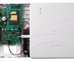
The communicator also has a sealed lead acid battery backup so that if you lose power to this unit, whether it's damage to this unit, damage to the wire of this unit to here, or just a simple power outage, or a power outlet issue, this communicator will still work because of the battery backup.
Same idea. Every alarm system is powered by a transformer. And if the transformer gets unplugged or there's a power outage, this system has a battery backup. So the important thing is that your communicator will be ready when you need it, as long as you're powering it with the right transformer and have the battery backup.
In addition to that equipment, you're going to want a good pair of wire strippers. You're going to want a nice little screwdriver, which will fit the terminal screws, both on the panel and the communicator that we're going to use to land the wiring to. And we, of course, need some wire.
We have 22 gauge four conductor wire, or commonly called 22 four. This is solid core wire. Although, you can certainly use stranded wire, as well. Sometimes that's easier to work with. It doesn't really matter. It doesn't have to be shielded or anything fancier than that.
So 22 is the gauge, or the thickness, of the conductors. Not the thickness of the white sheath. It's the thickness of the conductor on the inside. And when we're talking about conductor it's how many little wires are within the white sheath. So in this case, 22 four is four conductor. We have four different colors. Four different wires that we can use to connect the communicator to the panel.
So now that we know what we need for this project, we're going to show you how to complete this project. So your VISTA-20P panel, as we discussed, is powered by its own plug-in power supply, which is just a two prong transformer plugged into a standard wall outlet.
The most common one you'll find on a VISTA-20P is a 1321 Honeywell transformer, which is a 120 volt input meaning, a standard 120 volt outlet. And it outputs 16.5 VAC, 25 VA. So that's the rating of this transformer. And that's the rating that's needed for a 20P.
The iGSMV4G comes with a 1361 transformer from Honeywell, which is the same 120 volt input from the regular standard wall outlet. And it's also 16.5 VAC output. But it is a 40 VA. So it's a higher voltage rating to give more power.
What you can do-- oftentimes, where your panel transformer is plugged in, you may not have an available outlet. So while you normally wire your iGSMV4G and mount it on the wall near your 20P panel, you may not have an available outlet. And that can be a problem for some people.
However, the good news is, you can simply use a shared transformer. So instead of wiring off your iGSMV4G to this transformer and plugging this into an outlet, you don't have that spare outlet, then you simply change this 1321 transformer that powers the panel out to the bigger 1361 transformer that comes with the idea iGSMV4G.
Once you do that, you can use this unit to provide power to both systems or both devices in parallel. What that means is you would use the existing wiring from the 20P. On the 20P, the first two terminals of the panel are the AC input terminals, power terminals.
AC is not polarity conscious. So there's no positive or negative. You simply have a two wire connection. One and two. Runs through the wall and comes out wherever this is plugged into the wall. You have two screw terminals on the back of the transformer that you'll see once you unplug it.
And if you were to disconnect these two terminals by simply unscrewing them, you would, of course, want to make sure you've removed this from the outlet and also disconnected a lead from your backup battery on your panel.
So now you have your panel fully powered down. And you can disconnect the existing wiring, which is no longer live, to the 1321, the smaller transformer. And on the back of the 1361, you have the same two screws. Again, it's AC power. So there's no positive or negative. There's no polarity. You simply land one to one, and one to the other.
Honeywell now sells the 1361 as a 1361-T. And that would have a third screw. But you don't have to worry about that middle screw. That's just the grounding screw. I'm sorry. 1361-GT, as in grounding terminal. And again, that would be in the middle. A lot of people get confused and think they go A, C to GT, the grounding terminal. You don't. You just do the two AC terminals.
So we're using the existing wiring that's run through the wall. You want to make sure you screw it down nice and tight so the wire doesn't come loose like it just did to me. You'll find often that the wire that's already landed to the old terminal has a nice little fish hook on the end so that you can wrap it around the screw terminal and make a really good contact so that you don't have any loose connection or bad connection.
All right. Now we have a nice tight connection on both terminals. And we now have a transformer, which will work just fine to power the 20P, and more importantly, has an enough VA rating that we can run a two wire connection off of one and two on the panel and land it on terminals one and two on the iGSMV.
And again, we've now eliminated the need for a second outlet to be near where we're going to install this unit, because we're using the one transformer to run power to here. And then we have our one and two connection off of here going to one and two on here.
And the 1361 powers both units. And it is approved wiring set up when using the iGSMV4G. If you happen to have the other outlet, it's even easier. Just run one and two off here to the 1361 the and leave the panel power alone.
So now that we've reviewed the different ways to run power to these units, I'm going to swap my panel and my communicator so that you have a nice view of both. And we're going to detail the wiring that goes between the two and the wiring to the transformer.
So we're going to cut a length of wire off of our spool of 22 four. And depending on where you're mounting this, most people just mount it right to the side of the panel, so you don't need very long wire. But you simply cut a length for how long you need between the two devices.
And you strip off the outer sheath using your wire strippers. And you have your four conductors. And again, you're going to have to strip the ends of each conductor. This is 22 gauge.
And on the other end we already stripped the sheath to explain what 22 4 is. But we do need to strip each conductor. And now we have nice clean ends on both sides, four conductor each.
This wire is traditional color, which is black, red, yellow, and green. If you have wire that has different color, it doesn't matter. Don't get hung up on the color. It's all about which terminal on here is going to which terminal on here. We're, of course, going to show you the proper convention for the color. But again, it really doesn't matter. If your wire is a different color, it's still going to work.
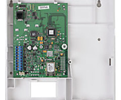
So even though we're getting power to this and to this, off the transformer, there's still a power connection from here to the panel's power output. And that starts on terminal number three, on the iGSMV4G. I'm going to turn my unit here so you can see the numbers of the screw terminals and follow along with what I'm doing here.
So terminal number three, on the iGSMV4G, goes to terminal number five, counting from the left, on the 20P. And that is your positive power output. So the panel gets power input from the transformer, 16 and 1/2 volts, and pushes out 12 volts on terminal 5. And the ground, or the negative output for that 12 volt power output is number four. And that's what we're going to connect first, is those power connections.
So we land our red wire, or our positive wire, to terminal 3. On this terminal block-- I'm going to show you how this works-- there's screws on the back side here. And on the front side you can see there's a gap on all the ones I haven't wired yet.
That gap means it's open, the terminal block is open. You can fit your wire in. And then on the top side you screw it down. And it closes the terminal connection to keep your wire tight. So those terminals are what they use on the iGSMV4G.
On the 20P it's more of just the simple screw with a contact underneath. And you just loosen the screw enough that you can fit your wire underneath, making sure that you're not extending your exposed wire too far where it can jump over and touch any of the other terminals.
They do have these black blocks to prevent that type of thing but depending on how long you strip your wire, we have seen people where it gets a little messy in there. So you don't want to go too far or too big on this portion of the wire.
Also, we have a nice clean panel here. When you're adding this to your systems, you're going to have a lot of things wired on here. If you have keypads, they're wireed here. If you have wireless receivers, they're wired here. If you have four wire or motion detectors, or glass break detectors, or smoke detectors, they're going to be wired here.
So don't get confused by that. All you simply do is land multiple wires onto the same screw terminal, making sure that you don't let any of the existing wires fall out. If they do fall out, make sure they go right back to the same terminal they were on.
So again, you can land multiple wires under one screw on this panel. As long as the wire connection on your wire is making contact to the metal screw, you're good to go. So again, we have terminal three on the iGSMV4G to terminal 5 on the VISTA-20P.
Now we go to the next one. On terminal 4 is our black wire. We insert the wire to the open terminal block. Make sure it's in there. I know we're blocking the view right now. But just to make sure it doesn't fall out, you get it nice and tight on the top, give a little tug to make sure it's not loose. You don't want these wires falling out. You're going to have issues with supervision of this unit to here.
And on this side, four goes to four. So again, you're going to have other things landed on four here. You just loosen the screw enough to be able to fit your black wire and land it to four. That is your power connection so that if you did lose power from the transformer the VISTA-20P is still feeding power over to this unit to keep it held up.
So now we need our data connection. Data is data in and data out. And that's our green and our yellow wires. So we're going to do terminal number five on the iGSMV4G. It is the yellow wire. Feed the wire into the opening. Screw it down tight. Make sure you give a little tug, it doesn't fall out. 5 on the iGSMV4G goes to 7 on the 20P.
When we talk about data in and out we're talking about a device that needs to be able to pass data to the panel and vice versa. So when the panel has an alarm signal, it needs to pass that data to the communicator so it can send its signal to Honeywell's servers for central station and/or Total Connect service. So that's why we need four connections, power and data.
So we've got five to seven data. And now we have six on the iGSMV4G. Goes to six on the 20P, which is our last keypad bus terminal that is not used. Open up the screw terminal to fit the green wire under. Make sure we're not loosening any other connections that might already be present there. Screw it down.
So now we're fully connected, wire to wire. In this case, you would want to have run the wire through a knockout on the control panel so that when you close your panel lid you're not crimping this wire. I failed to do that here. But they have multiple knockouts that you can use on this 20P cabinet. There's one here. There's some on the top.
And so you can kind of pry those out and feed your wire through there so that when you close your cover, you're not going to be pinching this wire. The important thing is to get your connections mapped properly.
So with those connected, we can now address the power connections to the and iGSMV4G. We don't want the panel feeding power to here all the time. We want the transformer to be feeding power to here and the panel is only here as a backup when you lose power to the transformer.
And again, you would have wanted to feed these wires through this back hole on the iGSMV4G, or try to notch the plastic out here. There's a little tab that you can notch out so that when you have the cover on the iGSMV4G, you're not pinching this wiring.
So we're going to need another length of wire. If you get a length of 22 four, just make sure you have enough for this connection, and then enough for another connection from here to your transformer, however far that may be, if you're doing the separate transformer.
If you're doing the shared transformer that we discussed, then you don't have to run to the transformer, because the transformer is already feeding power to the 20P. And you're just making your one and two connection on the iGSMV4G to one and two on the panel. So that bigger 1361 transformer is powering both units in parallel.
So we're just going to cut another similar length the wire. We strip our white sheath off to expose the internal conductors. And just for convention, we can use black and red, which is normally used for power.
You can even double these wires up if you were using skinnier 22 gauge wire. Oftentimes, you'd want to use probably 18 gauge wire when running direct to your transformer. Power wire you want to be a little bit thicker, depending on your wire run. In this case, with such a short run, 22's fine.
I'm just going to trim back the green and the yellow conductors and just use the black and the red. So we strip the ends. And we have our connection that we can land here. Strip the other end. Trim back the green and the yellow. Strip the red and the black.
And we now have our wire ready to connect from one and two the 20P, to 1 and 2 on the iGSMV4G. This is AC power. Again, no polarity. There's no positive or negative. You simply land each one. And make sure to screw it down tight.
And you want to tug on the wire. After screwing, you want to make sure it's not coming out. You don't have to pull too hard. But just give a nice little tug to make sure it's not loose. Then you put your black into the other terminal that you did. In this case, we did red on two and black on one. You could have done the opposite. It would work the same.
You would feed your wiring through the wire channel that you knock out here, or through the back. If you've got a hole that you can run through the wall, you would either come in through the back of here. There's knockouts in the 20P. There's knockouts along the 20P. And you feed it in to the panel up. To keep things consistent we can certainly put red to red and black to black. It doesn't matter. You could swap it. AC power, no polarity.
Last connection. Tighten it down. Give a nice little tug. Make sure nothing-- oh, and lo and behold, this one came out on my tug. So we're going to make sure that one gets down nice and tight. We would never want that to fall out on its own, especially because once we plug that transformer in, that's a live wire. You would never want that to fall out and touch anything else on this board, potentially do damage to the board.
So now we have our ECP connection, data and power, three to five. Four to four. Five to seven. And six to six. And we have our power run shared transformer one and two to one and two. And then one and two to the 1361 transformer. And that is all of the connections that we need.
At this point we can plug our battery leads back in. We've got our one red connection disconnected to keep the unit fully powered down. You'll notice that on the iGSMV4G, it will power up off the battery only.
So as soon as I'm touching this lead to the terminal, we're seeing light activity on the board. So this will power up off its battery only. Whereas, on the 20P, when you connect your battery, it's still not powered until you plug your transformer back into your standard wall outlet.
So the last step is plug this in. You'll often see there's a screw, which we just have removed right now. That if you remove the screw in the center of your two outlet wall plate, you can screw it through here, into your wall plate, to hold the wall plate to the outlet, so that this doesn't get unplugged accidentally.
If someone sees this screwed into the outlet they're never going to unplug this. That's because this is critical. You don't want this getting unplugged, because you don't want your panel or your communicator to lose power once the battery's drained.
You don't want your cleaning lady to say, I need an available outlet for my vacuum cleaner. I'm just going to unplug this for a little while. That screw will prevent someone from accidentally unplugging this, not realizing what it's doing.
So now that you've got this connected, we've got our proper prom. We now have a system that can be monitored, either internet, cellular, or dual path. It can do central station service, and/or Total Connect 2.0 service. And with the right monitoring service, you're all set up.
So if you have any questions on wiring up any of the AlarmNet Communicators, whether it's iGSMV4G, the 7847I, the GSMV4G to your VISTA-20P, VISTA-15P panel, please email support at alarmgrade.com. If you enjoyed this video, please hit like below and make sure to subscribe to our channel.
- Uploaded