Tips for Installing AlarmNet Cellular Communicators - Dated 09/27/17
Related Products
Related Categories
Document Transcript
9/27
/2017
Page |
1
of
3
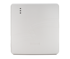
Tips for Installing AlarmNet Cellular Communicators
Overview
This document
will provide guidelines and “best practices” that should be observed when installing AlarmNet
cellular
communicators. Most of these are pulled from various Installation man
uals and are provided here
collectively.
Following these practices will help to ensure the device is installed properly
for correct operation
and communication with the cellular network.
Table of Contents
Overview
................................
................................
................................
................................
........................
1
Table of Contents
................................
................................
................................
................................
..........
1
Cell Communicator
–
General Tips
................................
................................
................................
...............
1
Cellular Remote Anten
na
–
General Usage and Install Tips
................................
................................
........
2
EC/NO and Ec/IO (Signal to Noise Ratios)
–
General Info and Install Tips
................................
..................
3
Cell Communicator
–
General Tips
F
or reliable
service, the communicator should only be installed in a location that supports consistently
satisfactory signal strength
.
If fluctuations into unsatisfactory ranges are observed, the device should be
relocated. Refer to the product installation instructi
ons for recommended signal strength ranges.
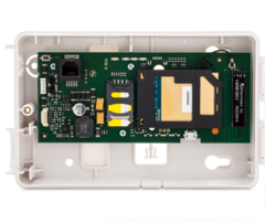
When choosing a suitable mounting location, understand that it must be mounted indoors
and should be
placed in a climate controlled environment.
F
or best signal strength
, the device
should be mounted vertically
.
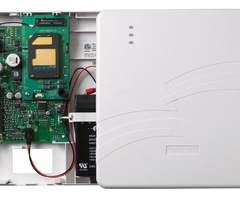
If the control panel location does not
support
adequate signal strength
or EC/NO (see page 3)
, the
communicator may be mounted remotely
(
while observing wiring limitations
provided in the
panel and/or
communicator
installation guide).
Find the best
location before mounting and wiring the radio by moving the module to several locations
while monitoring the signal strength
and EC/NO
.
The best signal strength can usually be found on an exterior wall at the highest point in the
building.
You typically w
ant to avoid the basement unless a remote antenna is being used.
Maintain at least 12 inches of clearance between the module and steel I
-
beams, HVAC ducts, metal
studs, steel roofs, or roofs and exterior walls with metalized insulation, aluminum siding, an
d other large
metal objects
.
When possible
,
avoid mounting on brick, stone
,
or concrete walls as they attenuate RF more than stud
walls
.
If consistent signal strength
or EC/NO
cannot be found with the internal antenna, an external, remotely
located ante
nna should be used
.
9/27
/2017
Page |
2
of
3
Microcells
act
like a mini cell tower in
a
premise
to improve indoor cell coverage, but
can
interfere
with
Honeywell 3G/4G
Cellular Communicators. Refer to
Technical Notification 10
–
Microcell
Interference
available @
https://mywebtech.honeywell.com/Intrusion/DocSearch
Cellular Remote Antenna
–
General Usage and Install Tips
If consistently satisfactory
signal strength
or EC/NO
cannot be found with the internal antenna, an external
antenna
may
be used
.
The following tips should be observed when usi
ng an external antenna.
The internal or external antenna(s) used with this product must be installed to provide a separation
distance of at least 7.8 in from all persons and must not be co
-
located or operating in conjunction with
any other antenna or tra
nsmitter except in accordance with FCC multi
-
transmitter product procedures
.
The external antenna must not exceed a maximum directional gain of 3.2 dBi at 850 MHz and 2.3 dBi at
1900 MHz
o
E
xternal antennas are available separately and meet this requirement
when installed according
to the instructions.
Adjust the location of the antenna until the signal strength is at a satisfactory level.
o
When
identifying
a suitable location for the exterior 3dB antenna, it is helpful to carry the cellular
communicator (oper
ating on battery power) to the proposed mounting location to determine the
signal levels and signal to noise ratios
that will be available to the antenna at that location.
If the signal level and/or signal to noise ratio is unacceptable (as determined by
the
communicator itself), DO NOT mount the antenna at that location and find a different,
more suitable mounting location.
It is suggested to perform this procedure to ensure the antenna is being placed in a
suitable location before drilling the mountin
g holes and routing the antenna cabling.
All antennas should be mounted vertically while maintaining 12 inches of clearance from large metal
objects.
o
Permanently mount the antenna using the included hardware.
Interior Antenna, part number CELL
-
ANT is an
indoor
fixed length antenna
that
should be used in
installations where moving the antenna to a higher point within the building will provide better RSSI
.
o
CELL
-
ANT c
able length is fixed at approximately 10 feet.
Exterior Antenna, part number
CELL
-
ANT3dB is a remote weatherproof antenna that should be used in
installations where the antenna must be mounted outdoors at some distance from the radio and gain is
needed.
o
The antenna is an exterior weatherproof antenna that can be mounted up to 50
feet away from
the radio when the proper coax cable is used. Honeywell offers this antenna in kits with a 25
foot cable or a 50 foot cable.
It is highly recommended to use the cabling available
in these kits
. Lower quality
cabling is not recommended due
to impendence and signal loss that can exceed the
gain provided by the antenna.
It is preferable to install the antenna with the 25 foot cable if that accommodates the
install.
DO NOT couple cabling together to extend the cable length and do not exceed 50 feet
of cabling.
9/27
/2017
Page |
3
of
3
This document contains Honeywell proprietary information. Information contained herein is to be used solely for the purpose s
ubmitted, and no
part of this document or its co
ntents shall be reproduced, published, or disclosed to a third party without the express permission of Honeywell
International.
HONEYWELL DISCLAIMS
THE IMPLIED WARRANTI
ES OF MERCHANTABILIT
Y AND FITNESS FOR A
PURPOSE AND MAKES NO
EXPRESS
WARRANTIES EXCEPT A
S MAY BE STATED IN I
TS WRITTEN AGREEMENT
WITH AND FOR ITS CUS
TOMER
. In no event is Honeywell liable to anyone
for any direct, special, or consequential damages. The information and specification in this document are subject to change w
ithout notice.
EC/NO and Ec/IO (
Signal to Noise Ratios
)
–
General Info and Install Tips
In addition to
the
received signal strength, anoth
er measurement that should be observed
and kept within
supported ranges
is the signal to noise ratio. This is referenced as
EC/NO on our 3G UMTS/HSPA+
(GSM) communicators and as
Ec/IO on our CDMA communicators. The signal to noise ratio should
always be
-
14 or better,
although we would suggest installation
in a location that allows for the best
possible
signal to noise ratio
to
maintain reliable connecti
vity t
o the cell network.
If required, t
he signal to
noise ratio may be improved by relocating the communicator or by use of an external antenna.
See chart
below for
acceptable levels for 3G/4G network and CDMA network
.
For the most consistent and reliable operation over the cellular network, both RSSI and signal to
noise ratios should be observed and improved when they fall out of acceptable ranges.
o
The signal to noise ratio may be improved by relocating the communicato
r or by use of
an external antenna.
o
Noise may vary with the number of subscribers connected to the same cell site at the
time of measurement. During busy periods the noise will increase, reducing the signal
to noise and resulting in a more negative number
.
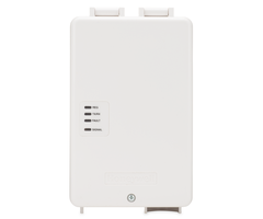
For devices with
LED indicators
for RSSI, the signal to noise ratio
is factored into the
indication
of good or bad coverage.
The Lyric and Gateway panels
also
factor the signal to noise ratio in the cellular RSSI reading.
The LYNX Touch panels DO NOT f
actor the signal to noise ratio in
the cellular
RSSI reading.
o
On the Lynx Touch
-
Signal to noise
is displayed as a separate measurement for CDMA
communicators
, but
is
not
available locally
for GSM
(check the GSM on AlarmNet 360)
.
Signal to noise values are
available on AlarmNet 360 as a separate measurement in the QoS
reporting for 3G/4G devices.
Signal to noise is displayed
locally
as a separate measurement on the 7720p (refer to product
Install Instructions).
- Uploaded