2GIG Go!Control: Installation of Wireless Security System
Related Products
Related Categories
Description
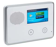
Sterling installs the 2GIG Go!Control onto a wall so that he can begin programming sensors
Transcript
Hi, DIYers. Sterling with Alarm Grid here. Today we're going to show you how to install a 2GIG Go Control Panel. If you've ever seen our YouTube channel before, this is the first time you've seen a non Honeywell product. This is a big release for Alarm Grid. We're finally branching out to offer other product lines beyond Honeywell. The 2GIG product lines the first thing that we're going to launch, this is powered by Alarm.com for monitoring service. So whereas Honeywell uses Alarmnet, which is an internal division for their internet and cellular communicators to provide cellular and Internet monitoring, and total connect interactive services, the 2GIG panels are powered by Alarm.com, which is a third party company that makes cellular units. They have Internet modules as well where, again, you can get monitoring without a phone line, and you can get system control from a computer, smart phone, mobile device.
So this is the latest and greatest 2GIG panel on the market. It is the CP21-345. The 345 stands for the 345 megahertz range in the RF radio frequency technology, and what that means is that the sensors that work with this panel are the 2GIG sensors which are on that frequency range. And also, if you know anything about Honeywell, the Honeywell sensors work on that same frequency. So you could use a 2GIG sensor with this panel, and you can also, without any other modules needed, learn in the Honeywell sensors. So any of the great Honeywell 5800 wireless sensors that you've come to know and love will be able to be used with this system. So the 2GIG product line with the range of sensors that they offer, they do have every, of course, door sensors, motion, smoke detectors, everything you would normally need but some of the more rare or custom Honeywell sensors that you may want, temperature sensors and things like that, could be enrolled to this system.
So we're very excited about this product launch, and we're going to show you how to put this system up on the wall. If you've ever seen our LYNX Touch L5100 video, this may look familiar to you because we actually had that panel mounted right here. The back plates aren't exactly the same, so we're going to re-drill holes, but you can see we're going to use our existing power wire, the LT cable that we use for the LYNX Touch. We are going to plug that into this panel, show you how to get this on the wall and get it powered up.
So we're going to review the tools we're going to need first. We need a Phillips head and flat head screwdriver. This one actually does both. So if you have one of these, you're probably in the alarm industry, but they are easy to get flathead and Philips' head screwdrivers. We have a drill for our three screws and wall anchors that will mount the panel to the wall, and we have a level to make sure it's nice and neat.
We're going to start by removing the backplate from the panel. There's a small screw right at the top here that needs to be removed, and then there are two tabs, right here, where you're going to want to flip over your flathead to pop the backplate from the from the front cover. So we swap our screw driver and we simply insert and pop each tab individually to remove the backplate from the panel. We've get one off, got the other off, and the backplate is removed. You can see the circuit board on the back here, we've got our backup battery. We have our siren, we have our power terminals and we have an input for a DC barrel plug. So a couple of different ways to power the system. We'll talk about that a little bit more in a second.
We also need a pen or pencil to mark our screw holes. This panel will ship with three screws and three wall anchors that you're going to use to mount this backplate to the wall. So that's the first thing we want to do is pick our location, mark our holes, and then get this back plate secure to the wall. When you're thinking about your installation of your panel, this is your wireless receiver to all of your sensors, your door sensors, motions, everything that you're using to protect your house. So you of course want to in an area that's going to be convenient for arming and disarming as you come and go from the property. But you also want it as centrally located it in the house as possible so that you get good wireless range out to all your sensors. They're not Wi-fi a lot of people assume that these panels are communicating via Wi-fi they're sensors but again it's on that 345 megahertz range on the radio frequency technology.
So, typically, you're going to get about a 200 foot range from this panel to any sensor in the house which should cover most environments, but if you have this on one side of your house, then maybe you don't get all the way out to the other side. If you put it in the middle then you're getting the biggest RF bubble that you can to cover the whole entire house. So we are right near our garage entry door where we mostly enter the house, and we're also centrally located. The living room is one room over and this is a perfect installation location for us, and the reason why we chose to put LYNX Touch here.
So here we go. We're going to put our panel up here, and we're going to keep it in line with our thermostat that we have over here, our Z-Wave thermostat, and we're going to use our level to make sure that we have it nice and neat on the wall. We want to use this area here. Since we already have our drywall hole, we're not going to make it any bigger. But you do have this entire cut out here. If you had a drywall saw, you could cut your hole for your for your power wire coming through so it fits in the back and you have this flush on the wall without any pinching of the wire. So we've got to make sure that this is lined up within the hole, and then we mark two at the top, and one at the bottom for our three mounting screws.
So we're in line with the thermostat. We are now level, and we just want to mark on the wall our screw locations. Again, two at the top and one at the bottom. Now that we have our marks, we can take our drill and drill our holes for our wall anchors and our screws. We've already cut power at our circuit breaker to this location to make sure that we're not going to have any risk drilling into the wall here.
Now we take our three white wall anchors that were shipped with the product. Push them in the wall. So I've got these wall anchors pushed in as far as I could. We used the 5/32 drill bit, maybe we could've gone a little bit bigger, but otherwise you can just tap these nice and flush to the wall, so that when we get our screws in there the panel will be flush to the wall. So the hammer might be a nice tool also to have. So we've got our three screws that came with the panel, that we're going to now screw into the three wall anchors and we're going to fit our backplate. You don't want to screw these all the way in until you got your back plate mounted, so you just one at a time ,get them almost all the way in, just a few turns before they're fully screwed to the wall.
So once you get the first two screws, you actually want to hold off on the third one, because if you look at the back plate, they gave you a handy little up arrow to show you orientation. Also you can use the backplate screw location to show you the top of the panel. The top two, you put the screws in, snap and snap shot in place, want to make sure you fish your power wire through the opening here. We've got a little piece of tape that we were using to hold the wire to the wall just so it doesn't fall back in the hole. And this third bottom screw now we can screw into place. You can always use your level just to make sure, in case your holes were misaligned at all, when you tighten your screws down you can always adjust a bit just to make sure you're nice and level for the permanent mounting.
So I made a slight adjustment there, and now I'm just screwing my screws tight to the backplate so it's not moving now. 2GIG has given us what they call a third hand which is nice right. We only have two, so we hang this little plastic tab here, right onto this little plastic mounting, and that allows us to hang the panel down without having to hold it, which makes it convenient as we hook up our wires.
Now that we have our control panel hanging from our secure backplate, nice and neat and level on the wall, I'm just going to point out what's on this board here so that you're familiar with your 2GIG Go control and everything that's involved here. So our circuit board, our brains of our panel is here, we have our 2GIG-REC2-345E. This is our wireless receiver for our wireless sensors. This module is built-in and included with every panel and will allow you to control any or work with any of the 2GIG wireless sensors. It'll also allow you to use the 2GIG Pad One which is an extra wireless keypad with button presses.
We described earlier that the 345 megahertz range is the same RF frequency that Honeywell sensors use. So this is the same wireless receiver that will work with Honeywell 5800 series sensors as well. The only device that does not work with this receiver is the 2GIG TS1. This is a really nice wireless touchscreen keypad, give you similar functionality to the main control panel in a remote location in the home. This device actually is 900 megahertz range. So this is only 345. It will not work with TS1. There is a 2GIG XCVR2, which is the alternative wireless relay module. You would remove this module, put the XCVR2 here. It's got a little pigtail antenna here that would come off and you would then have a dual channel wireless receiver so you could work with your wireless sensors, and you could work with that TS1 touch screen. So if you're interested in touchscreen keypads keep in mind that you'll need an alternative wireless receiver. This would pop out and you would install the XCVR2.
We have our backup battery included right in this portion here, It connects and plugs into the board on this two pin connector. This is the standard capacity battery that ships with the panel. There is a higher capacity battery to give you up to 24 hour backup battery runtime, and that battery would fit in this same location, you would just pop out the standard capacity battery. So again, if you're interested in a longer backup battery runtime, in case you have longer power outages frequently in your house, you could upgrade to a bigger, higher capacity battery. We have our siren right here. When the panel swings up, you can see on the other side, this is where the siren will emanate from. This is for our siren, our chimes, our voice annunciations. The panel makes the noise from the siren right here.
We have this blue button right at the bottom here, it's a push button. This is a tamper switch, and it's held down by this plastic tab at the top when the panels closed up. So when the panels closed up, if it were to be opened, this switch pops out and would indicate a case tamper. That is a signal that can be sent to the central station to let the Central Station know that someone tampering with your system, and is just an added protection in case someone's trying to open up your panel and do any kind of damage to the system.
We also have a strip of screw terminals on this terminal block, and I'm going to run through what all these terminals are. Starting at the top we have HW2 to and HW1. These are for if you want to hook up a wired zone to the system. So most people that get this panel, of course, are looking for a wireless system. They're going to have wireless sensors. But let's say you had a door right near your panel and there was an existing hardwired door contact, you could actually route your wire in through the back and connect to HW1 or HW2 and also the GND terminals a few down, the number three terminal. That would be your ground for your hard-wired zone, so you could actually hook up a sensor, or a series loop of multiple sensors and break it out over two different available hardwired zones on this Go Control Panel.
We have a negative and positive bell terminal, so if you want to hook up a wired siren you could do that by connecting to those terminals, and we have an open collector, basically, a trigger output that would allow you to activate other devices that are wired to the panel based on programmable actions that you would program for the open collector terminal. You have our ground, our GND. We already describe the ground is used for the hardwired. It's also used for the open collector, and then finally the bottom two terminals. Number one and two would be our negative 14BDC and positive 14 BDC. So unlike a lot of systems that use AC power, the Go control just like the LYNX Touch, uses a DC transformer which means you have to observe polarity and you have to make sure that you connect positive to the plus and negative to the negative. That's going to be if you're using your own custom wire. Of course you want to observe wire length and wire gauge requirements that are listed in the installation guides. So if you're going to have a really long run from your transformer, where you're plugged into a regular wall outlet, to your panel you're going to want to make sure you buy the proper wire for the length of the run that you're going to be using. So that's in the installation guide. And you want to make sure you don't exceed those limits.
In our case, we're going to use our wire that we were using for our LYNX Touch which has a DC barrel plug, and therefore we don't have to connect anything for DC power to the panel. We're just going to simply plug in to this port. You can't see it at the angle, but this is a barrel plug, a DC input for a DC barrel plug, so we don't have to worry about the screw terminals at all for our installation.
So now that we've described all aspects of our Go Control CP 21-345 control panel board, we're going to go ahead and power it up. So first thing we do, connect our battery. It's important that we do battery first before DC power so that if there is any kind of surge the battery will take it enough the circuit board we don't want damage the panel. So always battery first when powering up. You'll notice when we plug the battery in, we have no screen yet. That's just simply because the panel only powers up when it's got DC power from the wall outlet. This battery will only hold it up when you already have that power and you lose that power. So a lot of people get confused why is my panel not working? I plugged my battery in. That's by design don't worry.
So now that the battery is in, we're going to provide our DC power to the panel, and instead of hooking to our plus and minus 14 BDC terminals, we've got our barrel connector plugs directly to this input here. Nice and easy, no screws needed, or no screwdriver needed, and we're going to just close this panel. Sometimes you lose your connection on this third hanger when you try to close this. So just be careful when you ever go back to opening it you don't let it just fall down. Connect on the bottom first, and then it snaps shut on the top. Before we provide power, we want to do our final installation step of hooking or screwing our case to hold the control panel to the back plate. Now we're nice and secure on the wall it's not going anywhere, and our final step is to plug in our DC transformer.
All right. So we're down here by our two prong wall outlet. A lot of people don't realize that their alarm system is actually powered just from a transformer that simply plugs into a wall outlet. If you got like a hardwired system a lot of people have no idea that that transformer's powering their system somewhere in their house. A lot of times you have your control panel in a remote location, like a basement, or a utility room, or a laundry room, and instead of having the outlet right in that room, it may be fished through the wall to a remote location. In our case, we're directly below our control panel, and we have our wire fished coming here, and we're going to plug into this bottom plug with this transformer that comes with our 2GIG Go Control panel, and that's how we're getting DC power to our system.
This transformer, it's a little unique to Go Control. They have this nice little mounting bracket, which you peel the tape, and it sticks right to your wall plate. It has a hole in the top, and a screw that you can use if this outlet doesn't have it. But a lot of outlets the wall plate instead of a screw on the top on the bottom just has one right in the middle. So when you fix this here, you would take the wall plate off or the screw anyways, and then you would insert this screw that comes with the transformer and that's going to hold this clip to the wall outlet so that the cleaning lady, the family member that doesn't normally use the system, guest, anybody that tries to go grab this outlet is going to think twice before they unplug this because, again, this is a very critical electronic components in the home. You don't want to have it unplugged accidentally. So that's what this clip is all about and why you would get this screw. There's even a zip tie that comes with it, so that you can zip tie it, so that no one would ever unplug this unit.
So on the back of the transformer we have two screw terminals. This transformer is not going to come included with a wire already attached to the panel because 2GIG doesn't know how far your outlets going to be from your panel. We talked earlier how you have to be within the listed wire gauge and wire length run, so however far you're going to run your wire there are certain limits to how thick the wire needs to be. With our run, we're a few feet and this is 18 gauge wire, we're well within the limit.
So we're going to peel our tape, and we're going to simply affix this clip so it's centered over that bottom outlet. So now that we have our clip affixed to our outlet, we have our wire, it's got two spade connectors, one for red for positive, one for black or negative. If you're using your own custom wire, you're just going to have two conductors. You may not even have red and black. It doesn't really matter what the color is, it just matters that if you're connected to positive 14 VDC, that color wire needs to connect to the positive terminal on the transformer.
You probably can't see it in the video, but right here in the plastic there is a positive on the left, and a negative on the right. They're marked DC, so that you know that polarity matters. If you've worked with other alarm systems that are AC transformer powered, polarity doesn't matter. So again, on this one it's critical that we connect positive to positive, negative to negative, otherwise we're never going to get power to our system.
So in our case, we use our spade connectors. We've already loosened up these screw terminals so that we have a gap here. And we just fit our spade terminal under the screw, red to positive, black to negative, and we screw these down nice and tight. We don't want this to ever come undone. We're going to have AC loss issues, and our system would lose complete power once the battery drained.
Now that we're connected, we give a nice little tug so we make sure we're secure. If you were going to use your own custom wire, a nice handy tip is if you're using solid wire, you don't have to worry about twisting. But if you're using stranded wire, you would twist the wires to get a nice tight connection. I like to put a little fish hook. If you wrap it around your screwdriver, you get a nice little hook, and you can feed that hook up and around each terminal to get a nice solid connection onto each terminal. With the spade connector, this is even easier.
We now open up our clips a bit, plug the unit in. We don't need to use our screw because, again, our wall plate doesn't have it, but that would get screwed in there. And the final step, again, to make sure, after we fish our wire back in the wall, and make it look as neat and clean as possible, we take our zip tie. We feed it through the two holes and pull it tight. You can snip the end but here, we are not going to have this transformer ever get unplugged by accident.
You certainly don't need to have this zip tie on here. If you need to ever power cycle your system, obviously you'd have to cut this and have an alternative zip tie to keep it secure. But there's other ways to secure this. You could run a length of thread or yarn or something, anything that would really hold this tight. And the real important thing is that we're trying to highlight to anybody that's going to go and unplug this that this is an important thing that should not get unplugged.
So now that our transformer's plugged in and secure, we're going to pop back up and check out the boot up sequence of the Go Control panel.
We now have screen activity. Takes a minute to to load. We just give this system some time to power up and we will then see the 2GIG Go Control CP21-345 powered on.
[System disarmed, ready to arm.]
You can hear again the siren voice enunciations come in here. Our home button lights up, and we finally have our nice graphic touch screen showing that our 2GIG Go Control now is ready to go.
We hope you've enjoyed this installation video, and we invite you to subscribe to our channel. If you have any questions on your 2GIG Go Control system installation, please email support@alarmgrid.com.
- Uploaded