DSC TL880LT/TL880LE - Dual-path Communicator - Install Guide - Dated 2020
Related Products


Related Categories
- LTE Cellular Communicators
- Verizon LTE Cellular Communicators
- LTE Cellular Communicators
- Internet Alarm Communicators
- Dual-Path Alarm Communicators
- AT&T LTE Cellular Communicators
Document Transcript
Digital Security Controls
TL880LTB Dual Path Controller
TL880LEB Dual Path Controller
TL880LEAT-LAT Dual Path Controller
TL880LEAT-PE Dual Path Controller
WARNING: This manual contains information on limitations regarding product use and function and
information on the limitations as to liability of the manufacturer. The entire manual should be carefully
read. - 2 -
Introduction
5
Features
5
Communicator ratings
6
Communicator compatibility
6
UL Installation Requirements
7
Installation
8
Tools and supplies required
8
Step 1: Enable module
9
Step 2: Connecting the module
9
Step 3: Verify installer code to activate Alarm.com module
10
Step 4: Perform dual-path test (module registration)
10
Step 5: Allow module to auto-program
11
Panel settings
11
Troubleshooting
14
Module status information
14
Troubleshooting LEDs
14
Various module states (modes)
17
Improving wireless signal strength
17
Walking the customer through new user setup on the web
18
Interactive Service Menu
19
Interactive menus
19
Installer programming
19
User functions
19
Limited Warranty
21
End User License Agreement
21
Regulatory Information
23 Warning: Installer Please Read Carefully
Note to installers
The warnings on this page contain vital information. As the only individual in contact with system users, it is the installer’s responsibility to bring
each item in this warning to the attention of all users of this system.
System failures
This system has been carefully designed to be as effective as possible. There are circumstances, however, involving fire, burglary, or other types
of emergencies where it may not provide protection. Any alarm system of any type may be compromised deliberately or may fail to operate as
expected for a variety of reasons. Some, but not all, of the reasons may be:
Accessbyintruders
Intruders may enter through an unprotected access point, circumvent a sensing device, evade detection by moving through an area of insufficient
coverage, disconnect a warning device, or interfere with or prevent the proper operation of the system.
Component failure
Although every effort has been made to make this system as reliable as possible, the system may fail to function as intended due to the failure of a
component.
Compromiseof radio frequency(Wireless)
A device's signals may not reach the receiver under all circumstances, which could include: metal objects placed on or near the radio path,
deliberate jamming or other inadvertent radio signal interference.
Criminal knowledge
This system contains security features which were known to be effective at the time of manufacture. It is possible for persons with criminal intent
to develop techniques which reduce the effectiveness of these features. It is important that your security system be reviewed periodically to
ensure that its features remain effective and that it is updated or replaced if it is found that it does not provide the protection expected.
Failureof replaceablebatteries
This system’s wireless transmitters have been designed to provide several years of battery life under normal conditions. The expected battery life
is a function of the device environment, usage, and type. Ambient conditions such as high humidity, high or low temperatures, or large temperature
fluctuations may reduce the expected battery life. While each transmitting device has a low battery monitor which identifies when the batteries
need to be replaced, this monitor may fail to operate as expected. Regular testing and maintenance will keep the system in good operating
condition.
Inadequateinstallation
A security system must be installed properly in order to provide adequate protection. Every installation should be evaluated by a security
professional to ensure that all access points and areas are covered. Locks and latches on windows and doors must be secure and operate as
intended. Windows, doors, walls, ceilings and other building materials must be of sufficient strength and construction to provide the level of
protection expected. A reevaluation must be done during and after any construction activity. An evaluation by the fire and/or police department is
highly recommended if this service is available.
Inadequatetesting
Most problems that would prevent an alarm system from operating as intended can be found by regular testing and maintenance. The complete
system should be tested weekly and immediately after a break-in, an attempted break-in, a fire, a storm, an earthquake, an accident, or any kind
of construction activity inside or outside the premises. The testing should include all sensing devices, keypads, consoles, alarm indicating devices,
and any other operational devices that are part of the system.
Insufficient time
There may be circumstances when the system will operate as intended, yet the occupants will not be protected from an emergency due to their
inability to respond to the warnings in a timely manner. If the system is remotely monitored, the response may not occur in time to protect the
occupants or their belongings.
Motion detectors
Motion detectors can only detect motion within the designated areas as shown in their respective installation instructions. They cannot discriminate
between intruders and intended occupants. Motion detectors do not provide volumetric area protection. They have multiple beams of detection and
motion can only be detected in unobstructed areas covered by these beams. They cannot detect motion which occurs behind walls, ceilings, floors,
closed doors, glass partitions, glass doors or windows. Any type of tampering whether intentional or unintentional such as masking, painting, or
spraying of any material on the lenses, mirrors, windows or any other part of the detection system will impair its proper operation. Passive infrared
motion detectors operate by sensing changes in temperature. However their effectiveness can be reduced when the ambient temperature rises
near or above body temperature or if there are intentional or unintentional sources of heat in or near the detection area. Some of these heat
sources could be heaters, radiators, stoves, barbecues, fireplaces, sunlight, steam vents, lighting and so on.
Power failure
Control units, intrusion detectors, smoke detectors and many other security devices require an adequate power supply for proper operation. If a
device operates from batteries, it is possible for the batteries to fail. Even if the batteries have not failed, they must be charged, in good condition
and installed correctly. If a device operates only by ACpower, any interruption, however brief, will render that device inoperative while it does
not have power. Power interruptions of any length are often accompanied by voltage fluctuations which may damage electronic equipment such
as a security system. After a power interruption has occurred, immediately conduct a complete system test to ensure that the system operates as
intended.
Securityand insurance
Regardless of its capabilities, an alarm system is not a substitute for property or life insurance. An alarm system also is not a substitute for property
owners, renters, or other occupants to act prudently to prevent or minimize the harmful effects of an emergency situation.
- 3 - - 4 -
Smokedetectors
Smoke detectors that are a part of this system may not properly alert occupants of a fire for a number of reasons, some of which follow. The
smoke detectors may have been improperly installed or positioned. Smoke may not be able to reach the smoke detectors, such as when the fire is
in a chimney, walls or roofs, or on the other side of closed doors. Smoke detectors may not detect smoke from fires on another level of the
residence or building. Every fire is different in the amount of smoke produced and the rate of burning. Smoke detectors cannot sense all types of
fires equally well. Smoke detectors may not provide timely warning of fires caused by carelessness or safety hazards such as smoking in bed,
violent explosions, escaping gas, improper storage of flammable materials, overloaded electrical circuits, children playing with matches, or arson.
Even if the smoke detector operates as intended, there may be circumstances when there is insufficient warning to allow all occupants to escape
in time to avoid injury or death.
Telephonelines
If telephone lines are used to transmit alarms, they may be out of service or busy for certain periods of time. Also an intruder may cut the
telephone line or defeat its operation by more sophisticated means which may be difficult to detect.
Warning devices
Warning devices such as sirens, bells, horns, or strobes may not warn people or waken someone sleeping if there is an intervening wall or door. If
warning devices are located on a different level of the residence or premise, then it is less likely that the occupants will be alerted or awakened.
Audible warning devices may be interfered with by other noise sources such as stereos, radios, televisions, air conditioners, other appliances, or
passing traffic. Audible warning devices, however loud, may not be heard by a hearing-impaired person.
IMPORTANT
This installation manual shall be used in conjunction with the control panel installation manual available online
from the DSC website at www.dsc.com. All the safety instructions specified within that manual shall be
observed. The control panel is referenced as the “panel” throughout this document. This installation guide
provides the basic wiring, programming and troubleshooting information.
The alarm communicator is a fixed, wall-mounted unit, and shall be installed in the location specified in these
instructions. The equipment enclosure must be fully assembled and closed, with all the necessary screws/tabs,
and secured to a wall before operation. Internal wiring must be routed in a manner that prevents:
l
Excessive strain on wire and on terminal connections.
l
Interference between power limited and non power limited wiring.
l
Loosening of terminal connections.
l
Damage to the conductor insulation.
Safety information
The installer must instruct the system user on each of the following:
l
Do not attempt to service this product. Opening or removing covers may expose the user to dangerous
voltages or other risks.
l
Any servicing shall be referred to skilled persons only.
l
Use authorized accessories only with this equipment.
l
Do not stay close to the equipment during device operation.
l
Do not touch the external antenna.
Safety instructions for skilled workers
When using equipment connected to the telephone network, always follow the basic safety instructions
provided with this product. Save these instructions for future reference.
Follow all WARNINGS AND INSTRUCTIONS specified within the manual of the alarm controller.
Do NOT connect this equipment to electrical outlets controlled by wall switches or automatic timers.
AVOID installing equipment near heaters, air conditioners, ventilators, and refrigerators.
AVOID locating equipment close to or on top of large metal objects, for example wall studs.
Safety precautions required during installation
NEVER install this equipment during a lightning storm.
Position cables so that accidents cannot occur. This equipment must be installed and used within an environment that provides the pollution degree max 2 and
over-voltages category II NONHAZARDOUS LOCATIONS, indoor only. The equipment is designed to be
installed, serviced and/or repaired by Skilled Persons only; (skilled person is defined as a person having the
appropriate technical training and experience necessary to be aware of hazards to which that person may be
exposed in performing a task and of measures to minimize the risks to that person or other persons).
Before installing/servicing, DISCONNECT the power and the telephone line of the alarm controller.
These safety instructions should not prevent you from contacting the distributor and/or the manufacturer to
obtain any further clarification and/or answers to your concerns.
Introduction
This guide provides installation and operating instructions for the Alarm.com communicator module. The
following sections offer you a brief overview of its capabilities. Some capabilities and features vary based on
the Alarm.com service plan selected. Visit www.alarm.com/Dealer or contact Alarm.com for more
information.
Note:
The Dual Path IP/LTE module is available in the model TL880LTB/TL880LEB/TL880LEAT-
LAT/TL880LEAT-PE.
The module contains the IP/Radio subassembly model ADC-620T and the PC-Link to RS422 conversion
interface. The module is compatible with PowerSeries Neo Alarm Control Unit models HS2128, HS2064,
HS2032 and HS2016 software versions 1.1 and above and PowerSeries Pro Alarm Control Unit models
HS3032, HS3128, and HS3248 software versions 1.0 and above.
The module enables wireless reporting of all alarms and other system events from the PowerSeries Neo and
PowerSeries Pro control panel using an all-digital, LTE wireless (cellular) network or an Ethernet network.
The module can be used as the primary communication path for all alarm signaling, or as a backup to a
telephone connection to the central monitoring station. The wireless alarm signaling and routing service is
operated by Alarm.com. The module also features integrated support for Alarm.com’s home automation
solution with built-in Z-Wave capabilities.
Note:
Alarm.com's home automation solution with built-in Z-Wave capabilities is not UL evaluated.
Contact information
For additional information and support on Alarm.com modules, initial account setup, home automation, and all
other Alarm.com products and services, please visit: www.Alarm.com/dealer or contact Alarm.com technical
support at: 1-866-834-0470.
Features
l
128-bit AES encryption via cellular and Internet.
l
Models TL880LTB and TL880LEAT-LAT have NIST validation certificate number 4684.
l
Models TL880LEB and TL880LEAT-PE have NIST validation certificate number 5100.
l
Back up or primary cellular alarm communication and Ethernet.
l
Remote firmware upgrade via cellular or Internet using Alarm.com management portal.
l
Full event reporting to central station.
l
Cellular periodic test transmission.
l
Integrated call routing.
l
Panel remote uploading/downloading support via cellular or Internet.
l
PC-LINK connection.
l
Programmable labels.
l
SIA and Contact ID (CID) formats supported.
l
Signal strength and trouble display LEDs.
l
Subscriber Identity Module (SIM) card included with communicator.
- 5 - - 6 -
l
Supervision heartbeats over Ethernet path or over the Cellular path, when the Ethernet path is known to be
in a trouble condition.
l
2-way audio capable when used with audio module HSM2955(R) - Refer to HSM2955(R) manual.
Communicator ratings
Model
TL880LTB and
TL880LEAT-LAT
TL880LEB and
TL880LEAT-PE
Power supply ratings
Input Voltage
11.3V - 12.5V DC
(provided by compatible DSC
control panel)
Current consumption
Standby Current (Average Value)
150mA
Alarm (Transmitting) Current (Peak Value)
400mA
Cellular Network
TL880LTB: LTE Verizon
TL880LEAT-LAT: LTE AT&T
TL880LEB: LTE AT&T/Telus
TL880LEAT-PE: LTE AT&T
Operating Frequency
TL880LTB: 700 / AWS1700 MHz
TL880LEAT-LAT: LTE bands 1,
2, 3, 4, 5, 7, 28
TL880LEB: 1700/1900
AWS700/850 MHz
TL880LEAT-PE: LTE bands 1,
2, 3, 4, 5, 7, 28
Environmental specifications
Operating Temperature
32°F to 120°F (0°C to 49°C)
Storage Temperature
-34°C to 60°C
Humidity
93% RH non-condensing
Mechanical specifications
Dimensions
6" x 8.9" x 1.3"
Weight
365g
Communicator compatibility
Communicator
Receiver/
Panel
Description
TL880LTB
TL880LEB
TL880LEAT-LAT
TL880LEAT-PE
Receiver
l
Sur-Gard System I-IP Receiver, version 1.13+
l
Sur-Gard System II Receiver, version 2.10+
l
Sur-Gard SG-DRL3-IP, version 2.30+(for Sur-Gard System III Receiver)
l
Sur-Gard SG-DRL4-IP version 1.20+(for Sur-Gard System IV Receiver)
l
Sur-Gard SG-DRL5-IP version 1.00+(for Sur-Gard System 5 Receiver)
Panel
l
HS2016, version 1.1+
l
HS2032, version 1.1+
l
HS2064, version 1.1+
l
HS2128, version 1.1+
l
HS3032, version 1.0+
l
HS3128, version 1.0+
l
HS3248, version 1.0+
Note:
Enter [*][8][Installer Code][900][000] at keypad to view the panel version number.
Products or components of products, which perform communications functions only shall comply with the
requirements applicable to communications equipment as specified in UL60950-1, Information Technology
Equipment - Safety - Part 1: General Requirements. Such components include, but are not limited to: hubs;
routers; NIDs; third-party communications service providers; DSL modems; and cable modems. UL Installation Requirements
Note:
For equipment used at the protected premises and intended to facilitate IP communications (hubs,
routers, NIDs, Digital Subscriber Line (DSL), cable models), 24-hour back-up power is required. Where such
cannot be facilitated, a secondary (back-up) communication channel is required.
Domain Name Service (DNS) programming is not permitted in UL1610 and ULC-S304 listed
systems.
- 7 - - 8 -
Installation
I
NSTALLATION
Follow these guidelines during installation.
l
Before affixing the communicator to a wall, verify the LTE signal level at the installation location. On a
keypad, press and hold the 5 key for 2 seconds to view the LTE signal level. An installation location with
a sustained signal level of two or more bars is recommended.
l
When using panel power for the module, do not exceed the panel's maximum rated total output power.
Refer to the specific panel installation instructions for details. Only one module can be used per panel.
l
Do not mount the module inside of the metal alarm panel enclosure.
Tools and supplies required
You will need the following tools and supplies:
l
Small flat-head and Phillips screwdrivers
l
Screws (included)
l
Antenna (included)
l
16 pin ribbon cable (included)
Alarm controller PCB
PCLINK_2
Alarm Controller Cabinet
TL880L
TB/TL880LEB
/TL880LEA
T-LAT/TL880LEAT-PE controller
A
B
D
C PCL-422
Mounted in Alarm Controller Cabinet
Con
troller Board
RX-
RX+
TX+
TX-
+12V
GND
+12V
GND
E
F
A
Red wire on alarm controller PCLink2 Header
B
Antenna access ports
C
Ethernet cable
D
Quad cables (100' / 30m maximum)
E
Red wire on PCL-422 PCLink Header
F
LTE Controller Board power terminals. Can be connected to power supply module.
Step 1: Enable module
For the Alarm.com module to communicate with the panel, section [382] option 5 at the panel must be set to
ON. This section is OFF by default and must be enabled for the system to function properly. This should be
done before connecting the PC-Link cable to power up the module to ensure all initialization commands are
processed properly.
Step 2: Connecting the module
Caution:
Power down the alarm panel by removing both AC and the battery prior to connecting the module.
1: Connect data bus
The maximum cable length permitted for the data bus is 100ft/30m.
l
Connect the
RX+
terminal on the module to the
TX+
terminal on the PCL-422
l
Connect the
RX-
terminal on the module to the
TX-
terminal on the PCL-422
l
Connect the
TX-
terminal on the module to the
RX-
terminal on the PCL-422
l
Connect the
TX+
terminal on the module to the
RX+
terminal on the PCL-422
2: Connect power
- 9 -
Installation - 10 -
Installation
The maximum cable length permitted for the power connection is 100ft/30m.
l
Connect the
GND
terminal on the module to the
GND
terminal on the PCL-422
l
Connect the
+12V
terminal on the module to the
+12V
terminal on the PCL-422
3: Connect the PC-Link cable
Note:
To ensure correct orientation, refer to items A and D in the wiring diagrams for the proper position of
the red wire on the PC-link cable.
l
Connect one end of the supplied PC-Link cable to the PC-Link header on the PCL-422
l
Connect the other end of the PC-Link cable to the PC-LINK_2 header on the alarm panel
4: Connect Ethernet (optional)
Note:
Refer to item C in the wiring diagram for the correct placement of the Ethernet cable.
l
Connect one end of the Ethernet cable to the Ethernet port on the communicator
l
Connect the other end of the Ethernet cable to the Ethernet port on the router
5: Connect remote external antennas (optional)
Remote external antennas are available for the module if there is inadequate cellular reception at the preferred
mounting location. Contact DSC technical support for antenna options.
The module has two covered access ports on the top of the enclosure. Remove the plastic tab covering the
desired port and either mount the antenna on the enclosure or use the opening to pass through the antenna cable.
Note:
Due to the curvature of the enclosure, the plastic port covers are NOT interchangeable. Ensure that any
unused ports are covered with their original plastic tab.
Warning
: The external antenna must be installed in a manner to prevent end users from accessing any
conductive part of the anntena or antenna cable (i.e., recessed mounting or equivalent).
6: Power up
Connect panel battery and AC power.
Step 3: Verify installer code to activate Alarm.com module
Alarms and other signals will not be sent to Alarm.com until the installer code is verified. To activate the
account, perform the following steps:
1. Press [*][8] to enter Installer Programming.
2. Enter the installer code.
3. Press [#] to exit Installer Programming.
To remotely activate a system that is already signaling, perform the following steps:
1. Go to www.alarm.com/dealer.
2. Go to the customer's account.
3. Select the error message at the top of the page.
4. Enter the installer code.
Step 4: Perform dual-path test (module registration)
To initiate module communication with Alarm.com and the cellular network for the first time, perform a
“Dual-Path phone test”. Note that the test can also be used at any time by the installer to force communication
with Alarm.com. To test the cellular path, press and hold [3] for two seconds. To test the broadband path,
press and hold [4] for two seconds. A Dual-Path test can also be completed through the Interactive Services
menu. To perform the Dual-Path test, press [*][6] followed by the master code and [04]. The panel indicates when the test has completed by activating the siren output on medium volume for 2 seconds
followed by full volume for 2 seconds. However, if the test was initiated via the [3] or [4] key, or through the
Interactive Services menu, the siren will not sound. All display lights and LCD pixels turn on. This indicates
that Alarm.com has received and acknowledged the signal. This does not guarantee that the signal went
through to a central station; it confirms that Alarm.com’s Network Operations Center received the signal. The
central station should be contacted directly to verify that the signal was received on the correct account and
that the central station routing settings have been set up correctly. If the signal does not go through to the
central station, the panel displays a “Failure to Communicate” message. Double check the account’s central
station Forwarding Settings on Alarm.com and contact technical support if the trouble persists.
Step 5: Allow module to auto-program
After a successful dual-path test, wait 2 minutes for the module to automatically program and initialize before
entering the Installer Programming menus. Entering Installer Programming during module initialization will
cancel the process. LCD keypads display a message indicating when auto-programming is occurring and when
it has completed. During the auto-programming session, the module automatically programs panel settings
required for proper functionality with Alarm.com as noted in the “Panel Settings” section.
Panel settings
Central station and telephone line settings
Central Station (CS) and telephone line settings will be automatically configured through the CS Forwarding
Settings page of the Alarm.com Dealer Site. The following are the panel settings that are configured through
the Dealer Site page (when required) and should not be configured in the panel:
Section Option
Description
015
7
Telephone line monitoring
300 [001]
--
Panel Communication Path - Receiver 1
300 [002]
--
Panel Communication Path - Receiver 2
300 [003]
--
Panel Communication Path - Receiver 3
300 [004]
--
Panel Communication Path - Receiver 4
301 [001]
--
Communication telephone number 1
301 [002]
--
Communication telephone number 2
301 [003]
--
Communication telephone number 3
301 [004]
--
Communication telephone number 4
309 [001]
--
System Call Direction - Maintenance
309 [002]
--
System Call Direction - Test Transmission
310 [000]
--
System account number
310 [001]
--
Partition 1 account number
310 [002]
--
Partition 2 account number
310 [003]
--
Partition 3 account number
310 [004]
--
Partition 4 account number
310 [005]
--
Partition 5 account number
310 [006]
--
Partition 6 account number
310 [007]
--
Partition 7 account number
310 [008]
--
Partition 8 account number
- 11 -
Installation - 12 -
Installation
Section Option
Description
311 [001]
--
Partition 1 Call Direction - Alarm/Restore
311 [002]
--
Partition 1 Call Direction - Tamper/Restore
311 [003]
--
Partition 1 Call Direction - Opening/Closing
312 [001]
--
Partition 2 Call Direction - Alarm/Restore
312 [002]
--
Partition 2 Call Direction - Tamper/Restore
312 [003]
--
Partition 2 Call Direction - Opening/Closing
313 [001]
--
Partition 3 Call Direction - Alarm/Restore
313 [002]
--
Partition 3 Call Direction - Tamper/Restore
313 [003]
--
Partition 3 Call Direction - Opening/Closing
314 [001]
--
Partition 4 Call Direction - Alarm/Restore
314 [002]
--
Partition 4 Call Direction - Tamper/Restore
314 [003]
--
Partition 4 Call Direction - Opening/Closing
315 [001]
--
Partition 5 Call Direction - Alarm/Restore
315 [002]
--
Partition 5 Call Direction - Tamper/Restore
315 [003]
--
Partition 5 Call Direction - Opening/Closing
316 [001]
--
Partition 6 Call Direction - Alarm/Restore
316 [002]
--
Partition 6 Call Direction - Tamper/Restore
316 [003]
--
Partition 6 Call Direction - Opening/Closing
317 [001]
--
Partition 7 Call Direction - Alarm/Restore
317 [002]
--
Partition 7 Call Direction - Tamper/Restore
317 [003]
--
Partition 7 Call Direction - Opening/Closing
318 [001]
--
Partition 8 Call Direction - Alarm/Restore
318 [002]
--
Partition 8 Call Direction - Tamper/Restore
318 [003]
--
Partition 8 Call Direction - Opening/Closing
350 [001]
--
Receiver 1 communicator format
350 [002]
--
Receiver 2 communicator format
384
2
Communicator backup options
Notifications
The following panel settings may alter the behavior of customer notifications:
Section Option
Description
015
4
If this option is ON, keyfob arming notifications will not be associated with a specific
user.
Panel settings changed automatically
Some panel settings are changed automatically when the module is connected to the control panel. These
settings should not be altered. They are:
Section
Option
Value
Description
015
6
OFF
Master code is not changeable and must be
OFF to ensure the module communicates the
correct master code. Section
Option
Value
Description
017
6
OFF
Daylights saving time must be disabled to
ensure panel time is accurate.
019
6
Set according to
dealer's Alarm.com
setting
Enables Duress Code changes from
Alarm.com.
024
5
OFF
Realtime clock must be disabled to ensure
panel time is accurate.
377
Swinger Shutdown
(Maintenance)
010
Swinger Shutdown for maintenance signals
must be set to 010 to ensure trouble
notifications can be sent.
377
AC Failure
Communication Delay
Random value between
001 and 030
AC Failure Communication Delay should be
set between 001 and 030 to ensure
notifications for power failures are received.
377
Wireless Device Low
Battery Transmission
Delay
001
Wireless Device Low Battery Transmission
Delay should be set to 001 to ensure
notifications for low batteries are received.
380
1
ON
Communications must be enabled for the
module to communicate with the panel.
380
2
OFF
System should transmit alarm restores
immediately when the zone is restored.
380
5
OFF
The redundant communications method must
be set as backup.
382
6
OFF
AC Failure Transmission Delay should be in
minutes.
804 [sensor #]
003
Five minute delay [07]
High Traffic Shutdown should be set to five
minutes for devices being used with
Alarm.com's Activity Monitoring.
Note:
This feature may reduce the battery life
of wireless PIR sensors. In order to avoid this,
hardwired PIR sensors may be used instead.
Clock
The module sets the panel clock when it connects to Alarm.com and then updates it every 18 hours. It is
important to select the correct panel time zone on the Alarm.com website, or the panel time will not be
accurate. If a system is powered up before the customer account has been created, the time zone will default
to
Eastern Standard Time.
- 13 -
Installation - 14 -
Troubleshooting
T
ROUBLESHOOTING
Module status information
Module status information for verifying and troubleshooting the module connection status or errors can be
found through the Interactive Services menus. To access these, press [
*
][
8
][
Installer Code
][
851
]. See the
following table for potential module states.
Status
Description
Idle
Most common state. Module is not actively sending data and no errors are present.
Roaming
Roaming on partner network.
SIM Missing
The SIM card is missing.
PowerSave
Mode
AC power is down.
Registering...
The module is trying to register on the LTE network.
Connection
Error
The module is registered on the LTE network but cannot connect with Alarm.com. Contact Alarm.com
technical support for more information.
Radio Error
Radio portion of the module is not operating correctly. Power cycle the panel and call Alarm.com
technical support if the trouble persists.
Server Error
Identifies a server error. If it persists, the account may have been set up incorrectly.
Connected
Currently connected and transmitting information to the Alarm.com servers.
Connecting...
In the process of connecting to Alarm.com.
Updating...
Updating signal level.
In addition, some of the information can be retrieved via long key presses from the keypad. Press and hold the
following panel keys for 2 seconds to display the given information on the panel display. Most messages are
displayed for less than 30 seconds but can be cut short by pressing the 0 Key for 2 seconds.
Status
keys
Description
1 key
10-digit module serial number needed to create the Alarm.com customer account.
2 key
Module firmware version (e.g., 181a).
3 key
Initiate communication test over the cellular path.
Important:
This test is required to correctly complete the installation.
4 key
Initiate communication test over the broadband path.
5 key
Wireless signal strength level and module status or error, if any. The panel will display the signal level in
bars (0 to 5) and as a numerical value (0 to 31) followed by the connection mode.
6 key
Battery voltage as read by the module, to two decimal places, and the AC power status. (e.g., Battery:
6.79v, AC Power OK).
7 key
Use only when instructed by Alarm.com Technical Support.
8 key
LTE frequency used by the module.
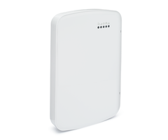
Troubleshooting LEDs
Status LEDs indicate network and module status. The following figure shows the location of the status LEDs
on the module. Status LEDs
L1 L2 L3 L4 L5
LED functions
LED
Function
1
General & Cellular Error LED. Flashes 1 to 8 times in an 8-second interval to indicate specific error. See section
“LED L1 (red)” for errors and common fixes.
2
Broadband Errors & Panel Communication. Flashes 2 to 8 times in an 8-second interval to indicate a specific
error on the broadband path. Also flashes once every time the module communicates with the panel. See
section “LED L2 (yellow)” for errors and common fixes.
3
Cellular Communication. Flashes every time the cellular signal level is checked and when packets are
exchanged with Alarm.com
4
Cellular Signal Strength Level. Flashes 0 to 5 times to indicate signal strength or toggles on/off slowly when
communicating with Alarm.com servers
5
Z-Wave Status & Error LED. See section “LED L5 (yellow)” for patterns.
LED details
LED L1 (red)
L1 flashes when there is a general error or an error on the cellular path. The number of flashes indicates the
error number. If there are two or more errors at the same time, the errors will flash one after the other. The
LED will stay off for at least four seconds between errors.
Number of
flashes
Error and solution
1
Module cannot communicate with the panel. Ensure section [382] option [5] is ON. Verify panel
software is version 1.1 or higher. Check the connectors (between the panel and communicator) and
powercycle the panel. If the error persists, there may be an issue with the module or panel.
2
The SIM card is missing. The SIM card holder can be found on the module. Verify that the SIM card
holder is closed securely and that there is a SIM card in the holder.
3
The module is trying to register on the LTE network. If it persists for more than a few minutes, the
module is having problems registering with the LTE network. Check L4 for signal level. If signal level
is lower than 2 “bars”, change the panel’s location or use a remote antenna option. If the signal is
good, the module may be roaming on a LTE network that does not partner with our LTE providers, or
the SIM card was not activated yet because the Alarm.com account was not created correctly.
- 15 -
Troubleshooting - 16 -
Troubleshooting
Number of
flashes
Error and solution
4
The module is registered on the LTE network but cannot connect with Alarm.com. Power down the
module, wait one minute, restore power and perform a communications test. Verify signal strength
and try a different location for the module/antenna. If the problem persists, contact Alarm.com
Technical Support.
5
Radio portion of the module is not working correctly. If this persists for more than a few minutes the
module may need to be replaced. This error is extremely rare so verify that the module is flashing 5
times.
6
This is an error only if it persists for more than a minute. Otherwise, it is just an indication that the
module is fixing an unusual condition regarding communication with the LTE network.
7
The module is not compatible with this panel type. Please insert a compatible module.
8
If it persists, the account may have been set up incorrectly. Contact Alarm.com Technical Support.
You will be asked to check the serial number of the module.
LED L2 (yellow)
LED L2 indicates an error on the Broadband path and also flashes with every communication between the
module and the panel when there is no error condition present. Normal pattern calls for a series of quick
flashes every two seconds in Idle mode or four seconds in PowerSave mode.
Number of
flashes
Error and solution
1
Flashes for each communication with the panel, except when LED is displaying a broadband error.
This is normal behavior.
2
The module cannot establish a connection with the router. Verify the physical connection/wiring to
the router. Verify MAC filtering is disabled on the router or add the module’s MAC to the allowed list
of MACs on the router. Verify that DHCP is enabled on the router.
3
The module cannot establish a connection with the internet. Verify other devices on the same
network can connect, that the panel has AC power, and that there are no special firewall or network
management settings running on the router.
4
The module cannot establish communication with Alarm.com. Contact Alarm.com Tech Support.
6
The Alarm.com backend cannot reach module due to an error with the local firewall blocking signals
from reaching the module.
LED L3 (yellow)
L3 flashes with every communication between the module and its radio unit in Idle mode, and with every
communication with Alarm.com in Connected mode. In PowerSave mode, this LED flashes in unison with
LED 2.
LED L4 (green)
L4 indicates the LTE signal level as a number of flashes (0 to 5 bars). The number of bars may not correspond
to the bars shown on your cell phone. A level of 5 bars is obtained only in the strongest signal conditions.
Signal level is updated every ten seconds if it fluctuates, or every 30 seconds if it is fairly stable. If L4 is not
flashing it indicates one of the following states:
l
The module is in PowerSave mode
l
The module just powered up
l
There is no LTE coverage in the area. Alarm.com recommends a steady signal level of 2 or higher for
proper operation of the module
Note:
In Connected Mode, the LED toggles on and off. LED L5 (yellow)
LED L5 indicates Z-Wave state and errors. See the table below for more information.
Number of flashes
Device status or error
1
Successfully added/removed node (last 60 seconds)
2
Delete Mode
3
Add node attempt failed (last 60 seconds) because device already in network
4
Add Mode
5
Replicate Mode
6
Learn Mode Error (lasts 60 seconds)
7
No Node Info
8
No other nodes are in the network
Various module states (modes)
There are four module states, or modes, as described in the following:
Mode
Description
Idle
AC power is okay and the module is not currently talking to Alarm.com.
L1 - Flashes general or cellular errors, if any
L2 – Flashes broadband errors, if any; Communication with panel
L3 - Communication with radio unit
L4 - Signal level (0 to 5 bars)
L5 - Flashes Z-Wave state or errors, if any
PowerSave
The module just powered up, AC power is down, or AC power was recently restored and the battery is
recharging. The module is fully functional and will go into Connected mode as soon as a signal needs to
be sent. Press and hold the 5 Key for 2 seconds to switch the module into Idle mode and update the
signal level reading. The system will go into Idle mode every 2 hours to check for any incoming
messages.
L1 - Inactive
L2 - Communication with panel
L3 - Same flashing pattern as L2
L4 - Inactive
L5 - Inactive
Connected
The module is currently talking to Alarm.com. The module stays in Connected mode for at least four
minutes after reporting an event to Alarm.com, unless the 5 Key is pressed and held for 10 seconds,
which will cause the module to go back to Idle mode.
L1 - Flashes general or cellular errors, if any
L2 - Flashes broadband errors, if any; Communication with panel
L3 - Communication with Alarm.com
L4 - Alternates two seconds on, then two seconds off
L5 - Flashes Z-Wave state or errors, if any
Sleep
The panel is not connected to AC power, or there is an AC power failure, and the battery level is low. The
module will connect to Alarm.com to send a signal, but will otherwise draw almost no power.
Note:
If the module is powered down for a short period of time, buffered messages from Alarm.com may be
received when module power is restored.
Improving wireless signal strength
As you make changes to the module location to improve signal strength, request updated signal readings to
verify changes. To request an updated reading, press and hold the “
5
” key for 2 seconds. In the image below,
- 17 -
Troubleshooting - 18 -
Troubleshooting
the radio has 3 out of 5 bars or 13/31 and is connected to the network.
Radio: 123__ 13
Connected
Guidelines for optimal wireless signal strength:
l
Install the module above ground level, as high up as possible within the structure.
l
Install the module near or adjacent to an exterior-facing wall of the structure.
l
Do not install the module inside a metal structure or close to large metal objects or ducts.
l
Upgrade the antenna. Contact DSC technical support for antenna options.
Walking the customer through new user setup on the web
This section describes how to help your customer set up their website account, and only applies to customers on
an interactive service plan with an online account. (Skip this step for customers using the module for wireless
signaling only).
Before the customer can configure their website account, the Alarm.com account for that customer must be
created on the Dealer Site, and the LTE module associated with the account must be installed successfully.
To log in and access their account, the customer can go to www.alarm.com (or custom dealer website address)
to complete the new subscriber setup procedure.
The customer will need the following:
l
The web site login and temporary password included on the Alarm.com Welcome Letter, which is
generated when the account was created by the dealer
l
A list of their system sensors with corresponding zone IDs
l
At least one phone number and e-mail address where notifications can be sent
Note:
At least one sensor must be learned into the panel to complete the new subscriber setup. If not all
sensors and touch screens were learned in before powering up the module, an updated sensor list must be
requested by performing a LTE phone test or requesting an updated equipment list from the Dealer Site. I
NTERACTIVE
S
ERVICE
M
ENU
Interactive menus
The “Interactive Services” menu can be used to access information about the module, install or remove Z-
Wave devices and configure or troubleshoot other interactive features.
The menu will time out after 20 minutes. Refer to the following tables for the menu options.
Installer programming
Press [*][8][Installer Code][851] to enter Interactive Services menu.
Menu
Description
--Alarm.com Module Status
Scroll down through the various Alarm.com module information screens.
---Radio
Signal level, connection status, roaming status, and errors (if any)
---LTE Freq.
LTE frequency used by the module
---SN
Module serial number. Needed to create or troubleshoot an Alarm.com account
---SIM Card
SIM card number. Sometimes needed to troubleshoot an account. Not applicable to
CDMA radios
---Version
Module firmware version and sub-version. Example: 181a; 181 =module firmware
version, a =subversion
---Advanced - Network
Use only when instructed by Alarm.com Technical Support.
--Z-Wave Setup
1
This menu is used to add, remove, and troubleshoot Z-Wave devices and
networks. To control Z-Wave devices via the Alarm.com website and smart phone
apps, you will also need to enable Z-Wave services on the account
--Number of Z-Wave
Devices
2
The total number of Z-Wave devices currently known to the module
--Add Z-Wave Device
1
Press [*] to enter Z-Wave Add Mode. Make sure the device being added is powered
up and within 3 to 6 feet of the panel. Refer to the manufacturer’s instructions for
button presses required to enroll devices
---Remove Z-Wave Device
1
Press [
*
] to remove an existing Z-Wave device, or to “reset” a Z-Wave device that
was previously learned into a different Z-Wave network. Previously enrolled
devices must be reset before they can be enrolled into the module
---Z-Wave Home ID
1
Press [
*
] to query the Z-Wave network Home ID. If the ID is 0, verify that the
module has communicated with Alarm.com and that the Alarm.com account is set
up for Z-Wave.
---Extended Range Option
Press [
*
] to enable/disable extended range
---Communications Test
Press [
*
] to perform ADC communication test
User functions
Press [*][6][Master Code] to enter User Functions menu. Then scroll to Interactive Services.
Menu
Description
--Alarm.com Module Status
See Installer Programming section
---Radio
See Installer Programming section
---LTE Freq.
See Installer Programming section
- 19 -
Interactive Service Menu - 20 -
Interactive Service Menu
Menu
Description
--SN
See Installer Programming section
---SIM card
See Installer Programming section
---Version
See Installer Programming section
---Advanced - Network
See Installer Programming section
--Z-Wave Setup
1
See Installer Programming section
---Number of Z-Wave Devices
1
See Installer Programming section
---Add Z-Wave Device
1
See Installer Programming section
---Remove Z-Wave Device
1
See Installer Programming section
---Z-Wave Home ID
1
See Installer Programming section
--Communication Test
See Installer Programming section
1
Refer to the Home Automation installation instructions and guides on the Alarm.com Dealer Site for more
information on Z-Wave enrollment and troubleshooting. Limited Warranty
Digital Security Controls warrants the original purchaser that for a
period of twelve months from the date of purchase, the product shall be
free of defects in materials and workmanship under normal use.
During the warranty period, Digital Security Controls shall, at its option,
repair or replace any defective product upon return of the product to
its factory, at no charge for labour and materials. Any replacement
and/or repaired parts are warranted for the remainder of the original
warranty or ninety (90) days, whichever is longer. The original
purchaser must promptly notify Digital Security Controls in writing that
there is defect in material or workmanship, such written notice to be
received in all events prior to expiration of the warranty period. There
is absolutely no warranty on software and all software products are
sold as a user license under the terms of the software license
agreement included with the product. The Customer assumes all
responsibility for the proper selection, installation, operation and
maintenance of any products purchased from DSC. Custom products
are only warranted to the extent that they do not function upon
delivery. In such cases, DSCcan replace or credit at its option.
International Warranty
The warranty for international customers is the same as for any
customer within Canada and the United States, with the exception that
Digital Security Controls shall not be responsible for any customs fees,
taxes, or VAT that may be due.
Warranty Procedure
To obtain service under this warranty, please return the item(s) in
question to the point of purchase. All authorized distributors and
dealers have a warranty program. Anyone returning goods to Digital
Security Controls must first obtain an authorization number. Digital
Security Controls will not accept any shipment whatsoever for which
prior authorization has not been obtained.
Conditions to Void Warranty
This warranty applies only to defects in parts and workmanship relating
to normal use. It does not cover:
l
damage incurred in shipping or handling;
l
damage caused by disaster such asfire, flood, wind, earthquake
or lightning;
l
damage due to causesbeyond the controlof DigitalSecurity
Controlssuch asexcessive voltage, mechanicalshock or water
damage;
l
damage caused by unauthorized attachment, alterations,
modificationsor foreign objects;
l
damage caused by peripherals(unlesssuch peripheralswere
supplied by DigitalSecurity Controls);
l
defectscaused by failure to provide a suitable installation
environmentfor the products;
l
damage caused by use of the productsfor purposesother than
those for which itwasdesigned;
l
damage fromimproper maintenance;
l
damage arising outof any other abuse, mishandling or improper
application of the products.
Items Not Covered by Warranty
In addition to the items which void the Warranty, the following items
shall not be covered by Warranty: (i) freight cost to the repair centre;
(ii) products which are not identified with DSC's product label and lot
number or serial number; (iii) products disassembled or repaired in
such a manner as to adversely affect performance or prevent adequate
inspection or testing to verify any warranty claim. Access cards or tags
returned for replacement under warranty will be credited or replaced
at DSC's option. Products not covered by this warranty, or otherwise out
of warranty due to age, misuse, or damage shall be evaluated, and a
repair estimate shall be provided. No repair work will be performed
until a valid purchase order is received from the Customer and a
Return Merchandise Authorisation number (RMA) is issued by DSC's
Customer Service.
Digital Security Controls’s liability for failure to repair the product
under this warranty after a reasonable number of attempts will be
limited to a replacement of the product, as the exclusive remedy for
breach of warranty. Under no circumstances shall Digital Security
Controls be liable for any special, incidental, or consequential damages
based upon breach of warranty, breach of contract, negligence, strict
liability, or any other legal theory. Such damages include, but are not
limited to, loss of profits, loss of the product or any associated
equipment, cost of capital, cost of substitute or replacement equipment,
facilities or services, down time, purchaser’s time, the claims of third
parties, including customers, and injury to property. The laws of some
jurisdictions limit or do not allow the disclaimer of consequential
damages. If the laws of such a jurisdiction apply to any claim by or
against DSC, the limitations and disclaimers contained here shall be to
the greatest extent permitted by law. Some states do not allow the
exclusion or limitation of incidental or consequential damages, so that
the above may not apply to you.
Disclaimer of Warranties
This warranty contains the entire warranty andshall be inlieuof
any andall other warranties, whether expressedor implied
(including all impliedwarranties of merchantability or fitness for a
particular purpose) Andof all other obligations or liabilities onthe
part of Digital Security Controls Digital Security Controls neither
assumes responsibility for, nor authorizes any other person
purporting to act onits behalf to modify or to change this warranty,
nor to assume for it any other warranty or liability concerning this
product.
This disclaimer of warranties andlimitedwarranty are governedby
the laws of the province of Ontario, Canada.
Digital Security Controls recommends that the entire system be
completely tested on a regular basis. However, despite frequent testing,
and due to, but not limited to, criminal tampering or electrical
disruption, it is possible for this product to fail to perform as expected.
Installer’s Lockout
Any products returned to DSCwhich have the Installer’s Lockout
option enabled and exhibit no other problems will be subject to a
service charge.
Out of Warranty Repairs
Digital Security Controls will at its option repair or replace out-of-
warranty products which are returned to its factory according to the
following conditions. Anyone returning goods to Digital Security
Controls must first obtain an authorization number. Digital Security
Controls will not accept any shipment whatsoever for which prior
authorization has not been obtained.
Products which Digital Security Controls determines to be repairable
will be repaired and returned. A set fee which Digital Security Controls
has predetermined and which may be revised from time to time, will be
charged for each unit repaired.
Products which Digital Security Controls determines not to be
repairable will be replaced by the nearest equivalent product available
at that time. The current market price of the replacement product will
be charged for each replacement unit.
End User License Agreement
IMPORTANT - READ CAREFULLY: DSCSoftware purchased with
or without Products and Components is copyrighted and is purchased
under the following license terms:
This End-User License Agreement (“EULA”) is a legal agreement
between You (the company, individual or entity who acquired the
- 21 - Software and any related Hardware) and Digital Security Controls, a
division of Tyco Safety Products Canada Ltd. (“DSC”), the
manufacturer of the integrated security systems and the developer of
the software and any related products or components
(“HARDWARE”) which You acquired.
If the DSCsoftware product (“SOFTWARE PRODUCT” or
“SOFTWARE”) is intended to be accompanied by HARDWARE, and
is NOT accompanied by new HARDWARE, You may not use, copy or
install the SOFTWARE PRODUCT. The SOFTWARE PRODUCT
includes computer software, and may include associated media, printed
materials, and “online” or electronic documentation.
Any software provided along with the SOFTWARE PRODUCT that is
associated with a separate end-user license agreement is licensed to
You under the terms of that license agreement.
By installing, copying, downloading, storing, accessing or otherwise
using the SOFTWARE PRODUCT, You agree unconditionally to be
bound by the terms of this EULA, even if this EULA is deemed to be a
modification of any previous arrangement or contract. If You do not
agree to the terms of this EULA, DSCis unwilling to license the
SOFTWARE PRODUCT to You, and You have no right to use it.
SOFTWARE PRODUCT LICENSE
The SOFTWARE PRODUCT is protected by copyright laws and
international copyright treaties, as well as other intellectual property
laws and treaties. The SOFTWARE PRODUCT is licensed, not sold.
GRANT OFLICENSE This EULA grants You the following rights:
Software InstallationandUse -
For each license You acquire, You
may have only one copy of the SOFTWARE PRODUCT installed.
Storage/NetworkUse -
The SOFTWARE PRODUCT may not be
installed, accessed, displayed, run, shared or used concurrently on or
from different computers, including a workstation, terminal or other
digital electronic device (“Device”). In other words, if You have
several workstations, You will have to acquire a license for each
workstation where the SOFTWARE will be used.
BackupCopy -
You may make back-up copies of the SOFTWARE
PRODUCT, but You may only have one copy per license installed at
any given time. You may use the back-up copy solely for archival
purposes. Except as expressly provided in this EULA, You may not
otherwise make copies of the SOFTWARE PRODUCT, including the
printed materials accompanying the SOFTWARE.
DESCRIPTION OF OTHER RIGHTS AND
LIMITATIONS
Limitations onReverse Engineering, Decompilationand
Disassembly -
You may not reverse engineer, decompile, or
disassemble the SOFTWARE PRODUCT, except and only to the extent
that such activity is expressly permitted by applicable law
notwithstanding this limitation. You may not make any changes or
modifications to the Software, without the written permission of an
officer of DSC. You may not remove any proprietary notices, marks or
labels from the Software Product. You shall institute reasonable
measures to ensure compliance with the terms and conditions of this
EULA.
Separationof Components -
The SOFTWARE PRODUCT is licensed
as a single product. Its component parts may not be separated for use
on more than one HARDWARE unit.
Single INTEGRATED PRODUCT-
If You acquired this
SOFTWARE with HARDWARE, then the SOFTWARE PRODUCT is
licensed with the HARDWARE as a single integrated product. In this
case, the SOFTWARE PRODUCT may only be used with the
HARDWARE as set forth in this EULA.
Rental -
You may not rent, lease or lend the SOFTWARE PRODUCT.
You may not make it available to others or post it on a server or web
site.
Software Product Transfer -
You may transfer all of Your rights
under this EULA only as part of a permanent sale or transfer of the
HARDWARE, provided You retain no copies, You transfer all of the
SOFTWARE PRODUCT (including all component parts, the media and
printed materials, any upgrades and this EULA), and provided the
recipient agrees to the terms of this EULA. If the SOFTWARE
PRODUCT is an upgrade, any transfer must also include all prior
versions of the SOFTWARE PRODUCT.
Termination-
Without prejudice to any other rights, DSCmay
terminate this EULA if You fail to comply with the terms and
conditions of this EULA. In such event, You must destroy all copies of
the SOFTWARE PRODUCT and all of its component parts.
Trademarks -
This EULA does not grant You any rights in connection
with any trademarks or service marks of DSCor its suppliers.
COPYRIGHT - All title and intellectual property rights in and to the
SOFTWARE PRODUCT (including but not limited to any images,
photographs, and text incorporated into the SOFTWARE PRODUCT),
the accompanying printed materials, and any copies of the
SOFTWARE PRODUCT, are owned by DSCor its suppliers. You may
not copy the printed materials accompanying the SOFTWARE
PRODUCT. All title and intellectual property rights in and to the
content which may be accessed through use of the SOFTWARE
PRODUCT are the property of the respective content owner and may
be protected by applicable copyright or other intellectual property laws
and treaties. This EULA grants You no rights to use such content. All
rights not expressly granted under this EULA are reserved by DSCand
its suppliers.
EXPORT RESTRICTIONS- You agree that You will not export or re-
export the SOFTWARE PRODUCT to any country, person, or entity
subject to Canadian export restrictions.
CHOICE OFLAW - This Software License Agreement is governed by
the laws of the Province of Ontario, Canada.
ARBITRATION - All disputes arising in connection with this
Agreement shall be determined by final and binding arbitration in
accordance with the Arbitration Act, and the parties agree to be bound
by the arbitrator’s decision. The place of arbitration shall be Toronto,
Canada, and the language of the arbitration shall be English.
LIMITED WARRANTY
NO WARRANTY -
DSCPROVIDESTHE SOFTWARE “ASIS”
WITHOUT WARRANTY. DSCDOESNOT WARRANT THAT THE
SOFTWARE WILL MEET YOURREQUIREMENTSORTHAT
OPERATION OFTHE SOFTWARE WILL BE UNINTERRUPTED
ORERROR-FREE.
CHANGESIN OPERATING ENVIRONMENT-
DSCshall not be
responsible for problems caused by changes in the operating
characteristics of the HARDWARE, or for problems in the interaction
of the SOFTWARE PRODUCT with non-DSC-SOFTWARE or
HARDWARE PRODUCTS.
LIMITATION OF LIABILITY; WARRANTY REFLECTS
ALLOCATION OF RISK -
IN ANY EVENT, IFANY STATUTE
IMPLIESWARRANTIESORCONDITIONSNOT STATED IN THIS
LICENSE AGREEMENT, DSC’SENTIRE LIABILITY UNDER
ANY PROVISION OFTHISLICENSE AGREEMENT SHALL BE
LIMITED TO THE GREATEROFTHE AMOUNT ACTUALLY
PAID BY YOU TO LICENSE THE SOFTWARE PRODUCT AND
FIVE CANADIAN DOLLARS(CAD$5.00). BECAUSE SOME
JURISDICTIONSDO NOT ALLOW THE EXCLUSION OR
LIMITATION OFLIABILITY FORCONSEQUENTIAL OR
INCIDENTAL DAMAGES, THE ABOVE LIMITATION MAY NOT
APPLY TO YOU.
DISCLAIMER OF WARRANTIES-
THISWARRANTY
CONTAINSTHE ENTIRE WARRANTY AND SHALL BE IN LIEU
OFANY AND ALL OTHERWARRANTIES, WHETHER
- 22 - EXPRESSED ORIMPLIED (INCLUDING ALL IMPLIED
WARRANTIESOFMERCHANTABILITY ORFITNESSFORA
PARTICULARPURPOSE) AND OFALL OTHEROBLIGATIONS
ORLIABILITIESON THE PART OFDSC. DSCMAKESNO
OTHERWARRANTIES. DSCNEITHERASSUMESNOR
AUTHORIZESANY OTHERPERSON PURPORTING TO ACT ON
ITSBEHALFTO MOD8IFY ORTO CHANGE THISWARRANTY,
NORTO ASSUME FORIT ANY OTHERWARRANTY OR
LIABILITY CONCERNING THISSOFTWARE PRODUCT.
EXCLUSIVEREMEDY AND LIMITATION OF WARRANTY -
UNDERNO CIRCUMSTANCESSHALL DSCBE LIABLE FOR
ANY SPECIAL, INCIDENTAL, CONSEQUENTIAL ORINDIRECT
DAMAGESBASED UPON BREACH OFWARRANTY, BREACH
OFCONTRACT, NEGLIGENCE, STRICT LIABILITY, ORANY
OTHERLEGAL THEORY. SUCH DAMAGESINCLUDE, BUT ARE
NOT LIMITED TO, LOSSOFPROFITS, LOSSOFTHE SOFTWARE
PRODUCT ORANY ASSOCIATED EQUIPMENT, COST OF
CAPITAL, COST OFSUBSTITUTE ORREPLACEMENT
EQUIPMENT, FACILITIESORSERVICES, DOWN TIME,
PURCHASERSTIME, THE CLAIMSOFTHIRD PARTIES,
INCLUDING CUSTOMERS, AND INJURY TO PROPERTY.
DSCrecommends that the entire system be completely tested on a
regular basis. However, despite frequent testing, and due to, but not
limited to, criminal tampering or electrical disruption, it is possible for
this SOFTWARE PRODUCT to fail to perform as expected.
Regulatory Information
FCC MODIFICATION STATEMENT
Digital Security Controls has not approved any changes or
modifications to this device by the user. Any changes or modifications
could void the user’s authority to operate the equipment.
Digital Security Controls n’approuve aucune modification apportée à
l’appareil par l’utilisateur, quelle qu’en soit la nature. Tout changement
ou modification peuvent annuler le droit d’utilisation de l’appareil par
l’utilisateur.
ISED CANADA INTERFERENCE STATEMENT
This device complies with Part 15 of the FCCRules and ISED Canada
licence-exempt RSSstandard(s). Operation is subject to the following
two conditions: (1) this device may not cause interference, and (2) this
device must accept any interference, including interference that may
cause undesired operation of the device.
Le présent appareil est conforme aux CNRd'ISED Canada applicables
aux appareils radio exempts de licence. L'exploitation est autorisée aux
deux conditions suivantes : (1) l'appareil ne doit pas produire de
brouillage, et (2) l'utilisateur de l'appareil doit accepter tout brouillage
radioélectrique subi, ême si le brouillage est susceptible d'en
compromettre le fonctionnement.
FCC CLASS B DIGITAL DEVICE NOTICE
This equipment has been tested and found to comply with the limits for
a Class Bdigital device, pursuant to part 15 of the FCCRules. These
limits are designed to provide reasonable protection against harmful
interference in a residential installation. This equipment generates uses
and can radiate radio frequency energy and, if not installed and used in
accordance with the instructions, may cause harmful interference to
radio communications. However, there is no guarantee that
interference will not occur in a particular installation. If this equipment
does cause harmful interference to radio or television reception, which
can be determined by turning the equipment off and on, the user is
encouraged to try to correct the interference by one or more of the
following measures:
- Reorient the receiving antenna.
- Increase the separation between the equipment and receiver.
- Connect the equipment into an outlet on a circuit different from that to
which the receiver is connected.
- Consult the dealer or experienced radio/television technician for help.
CAN ICES-3(B) / NMB-3(B)
FCC/ISED CANADA WIRELESS NOTICE
This equipment complies with FCCand ISED Canada radiation
exposure limits set forth for an uncontrolled environment. The antenna
should be installed and operated with minimum distance of 20 m
between the radiator and your body. The antenna(s) used for this
transmitter must not be co-located or operating in conjunction with any
other antenna or transmitter, except as described in this user manual.
Cet appareil est conforme aux limites d'exposition aux rayonnements de
la ICpour un environnement on contrôlé. L'antenne doit être installé de
façon à garder une distance minimale de 20 centimètres entre la
source de rayonnements et votre corps. L'antenne (s) utilisée pour cet
émetteur ne doit pas être situé ou opérant en conjonction avec une
autre antenne ou émetteur, sauf tel que décrit dans ce mode d'emploi.
Antenna gain must be below/Gain de l'antenne doit être ci-dessous:
Carrier
Frequency band (MHz)
Antenna Gain (dBm)
LTE Verizon
700 (B13)
6.94
AWS1700 (B4)
6.00
LTE AT&T/Telus
1700/1900
3.20
AWS700/850
4.40
Warning:
To satisfy FCC RF exposure requirementsfor mobile
transmitting devices, a separation distance of 20cm or more must
be maintained between the antenna of thisdevice and persons
during device operation.
For UL/ULCListed installation the products are intended to be installed
in accordance with the following:
A.
NFPA 70, "NationalElectricalCode."
B.
NFPA 72, "NationalFire AlarmCode."
C.
UL 1641, "Installation and Classification of ResidentialBurglar
AlarmSystems."
D.
NationalBuilding Code (NBC);
E.
CSA C22.1 - Canadian ElectricalCode, Part1;
F.
CAN/ULC-S302 - Standard for Installation and Classification of
Burglar AlarmSystemsfor Financialand CommercialPremises,
Safesand Vaults;
G.
CAN/ULC-S540 - Standard for the Installation of Residential
Fire Warning Systems;
H.
CAN/ULC- S310 - Standard for the Installation and
Classification of ResidentialBurglary AlarmSystems.
I.
CAN/ULC S301 - Standard for the SignalReceiving Centre
Burglar AlarmSystemsand Operations
J.
LocalAuthoritiesHaving Jurisdiction (AHJ).
K.
Manufacturer'sInstallation Instructions.
For UL Residential Fire and Burglary installations, the
TL880LT/TL880LE is listed as a sole means of communication or as a
back up when used in conjunction with a POTSline (dialer).
For UL Commercial Burglary installations, the TL880LT/TL880LE is
listed as a sole means of communication (supervision window of 200s
required at monitoring station) or as a back-up when used in
conjunction with a POTSline (dialer).
For ULC Commercial Burglary installations the TL880LE is listed as an
active communication system with line security level A1-A4 (90
second check-in signal enabled and 180 second supervision window
enabled at monitoring receiver and encryption enabled) and as a
passive communication system with communication line security level
P1 when used alone or as P2-P3 when used in conjunction with the
integrated POTSline (dialer) in the compatible NEO Alarm Control
- 23 - panels HS2128/HS2064/HS2032/HS2016. The TL880LE can be used in
commercial burglary applications up to Security Level IV. For
ULC Listed installations refer also to ULC Installation Guide P/N
29002157.
Notes for using Private, Corporate andHighSpeedData Networks
whenusing TL880LE:
Network access and domain access policies
shall be set to restrict unauthorized network access, and "spoofing" or
"denial of service" attacks. Select the internet service providers that
have redundant servers/systems, back-up power, routers with firewalls
enabled and methods to identify and protect against "denial of service"
attacks (i.e. via "spoofing").
For ULC Residential Fire and Burglary installations the TL880LE is
listed as a sole means of communication or as a back-up when used in
conjunction with a POTS line (dialer).
The TL880LT/TL880LE shall be powered from the compatible listed
control unit HS2128/HS2064/HS2032/HS2016 or compatible listed
power supply HSM2204/HSM2300 that complies with the ratings
specified in this manual.
- 24 - ©
2020 Johnson Controls. All rights reserved. JOHNSON CONTROLS, TYCO and DSC are trademarks of
Johnson Controls.
Tech Support: 1-800-387-3630 (Canada & U.S.) or 905-760-3000
www.dsc.com
The trademarks, logos, and service marks displayed on this document are registered in the United States and/or other countries. Any misuse of the
trademarks is strictly prohibited and Tyco will aggressively enforce its intellectual property rights to the fullest extent of the law, including pursuit
of criminal prosecution wherever necessary. All trademarks not owned by Tyco are the property of their respective owners, and are used with
permission or allowed under applicable laws.
Product offerings and specifications are subject to change without notice. Actual products may vary from photos. Not all products include all
features. Availability varies by region; contact your sales representative.
29010001R003
- Uploaded