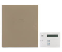
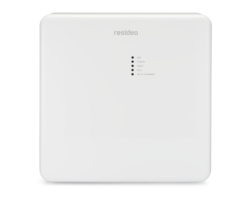
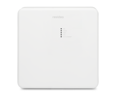
LTEM-PA or LTEM-PV: Installation with a Vista 20P
Related Products


Related Categories
- Small Business Security Systems
- Monitored Home Security Systems
- Dual-Path Alarm Communicators
- DIY Wired Security Systems
Description
In this video, Griffin from Alarm Grid shows you how to connect a Resideo LTEM-PV (or LTEM-PA) to a VISTA-20P panel when the ...
Transcript
[MUSIC PLAYING] Hello, DIYers. My name is Griffin with Alarm Grid. And today, I'm going to explain on how to connect the LTEM-PV series communicator to the VISTA-20P series panel on its own transformer. This is the non-share powered method of connecting it. The general reason why you would have to use the transformer is if you was going to use any of the peripherals that can be connected to the LTEM-PV series communicator such as the Wi-Fi card or the Pro dialer caption module. If you use any of those devices that's attached to the LTEM-PV, you have to use the transformer. So let's get into it today, shall we? So the tools that we will need today for this install is a screwdriver either Philips tip or flat tip, the transformer not really a tool, but it's there. And then one thing I do recommend you purchasing with the LTEM-PV if you're not doing the shared power is the LT cable for as you can see the LT cable is already stripped at the end and ready to be connected. And what it gives you, it gives you an easy, quick disconnect if you ever need to. So what we're going to start with today is the transformer. The one thing you want to pay attention to is the minus sign and the plus sign on top of the transformer because this has what's called polarity. So this is ground. This is positive voltage. And the way we're going to do this is we're going to use this end of the connector on the LT cable to connect it to the transformer. So just to reiterate, the black wire goes underneath the minus sign for a ground connection. Looks like it's already loose. So we're going to slide the spade connector underneath the screw. And then we're going to tighten it up. There's no need to power torque it, just a nice little corner turn there whenever it's tight. Then we're going to do the red cable underneath the positive terminal, the positive screw. We're going to slide a spade connector underneath there. And again, I must do just urgently pay attention to your polarity-- black wire underneath the minus sign, red wire underneath the positive sign. So now we're going to connect the transformer to the LTEM-PV. So again, it is polarity but on this one instead of a minus sign, you've got the letters GND which stand for ground. That's where your black wire is going to go. OK Now, your red wire is going to go underneath the plus 9 volt sign for that's your positive voltage. Again, this is for polarity reasons. And if polarity is incorrect, you could damage the system. Next, we're going to connect the LTEM-PV to the VISTA-20P utilizing this pigtail cable. That's what we call it. It comes with a green, black, and yellow wire attached to it. So we're going to connect the wires that we discussed earlier into this little port here. And the wire should be orientated as follows-- green, black, and yellow. And what we're going to do is we're going to run these wires into this little hole. Usually if you was using the bracket, you would run them through the bracket down into this hole but we're not doing that today. So we're just going to run the wires through the hole. And the terminals were going to use for this setup is terminals 4, 6, and 7 for these connections. The black wire is going to go into terminal 4. And you want to slide the wire in to try to keep his little copper as much as it exposed. You'll see there will be a little bit overhang, but there's nothing touching the board down there at the bottom. And again, the green wire is going to go to terminal 6. And then the yellow wire is going to go to terminal 7. Now if any of these three wires is not connected properly or if they are loose or disconnected, it will give you a 103 error on the keypad. So once you have all your connections made, we will begin the powering up process of the system. So what you want to do is you'd want to plug-in the LTEM-PV battery first, then plug in the transformer of the LTEM-PV, and then continue powering up your system, your VISTA system. And that's how you install the LTEM-PV onto the VISTA-20P and the non-sharing power method. If you have any questions, please send us an email to support@alarmgrid.com or visit us at our website at alarmgrid.com. If you found this video helpful, please hit the Like and Subscribe button. Also don't forget to hit the Bell icon to get notifications of future content that we make. My name is Griffin with Alarm Grid. And I'm happy to help.
- Uploaded