Resideo AlarmNet Cell-ANT3dB - Install Guide - Dated 11/20 Rev. A
Related Products


Document Transcript
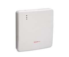
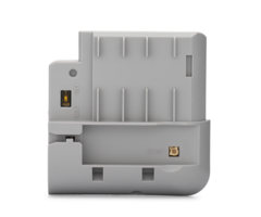
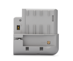
AlarmNet CELL-ANT3dB
Remote Weatherproof Antenna Kit
Installation and Setup Guide
General Information
CELL-ANT3dB supports 30 global cellular frequency b
ands for 4G LTE, 3G WCDMA and CDMA. It should be u
sed
on installations where the antenna must be mounted
at some distance from the communicator. The antenna
is
rated for outdoor installations but can also be mou
nted in attics, plenums and other indoor spaces.
Signal Strength
For reliable service, the communication module shou
ld only be installed in locations where there is sa
tisfactory
signal strength. The signal strength value is measu
red in dBm.
For the VISTA and Safewatch Pro Series controls the
signal strength can be viewed on the 7720P Program
ming
Tool, by using the
shift
command. The signal strength (green) LED lights st
eady to indicate satisfactory signal
strength.
For the L3000, L5000, L5210, L7000, PROA7 Series, t
he signal strength value can be viewed through Alar
mNet
360. Go to www.alarmnet360.com.
dBm is displayed as a negative value. A value close
r to 0 represents a stronger signal. (i.e.,
Signal strength of -60 dBm is stronger than that of
-100 dBm.)
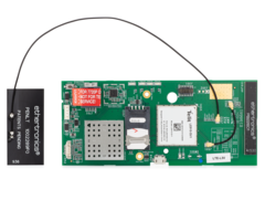
The CELL-ANT3dB Kit includes the following items:
CELL-EXTCX
MMCX-M to SMA-F Cable (p/n 600-00494V1)
SMA-M to SMA-F Coaxial Adapter (p/n R300-11296)
Cable tie (2) (p/n P3171)
CELL-EXT
u.FL to SMA Cable (p/n 600-00278)
Antenna Cable Removal Tool (p/n 700-03513)
WA7626-CA
SMA to N Cable
Antenna
LTE 50ohm, 100w (p/n 900-03021 with N7197 B
racket OR p/n 900-03137 with 700-05655 Bracket)
Additionally, an RF extension cable is required.
7626-50HC
50ft RF Extension Cable
7626-25HC
25ft RF Extension Cable
7626-5
5ft RF Extension Cable
For the correct cable applicability for your instal
lation refer to the table below:
LTE
MODULE
CABLE
Panel Compatibility
PROLTE-A
PROLTE-V
PROLTE-CN
CELL-EXTCX (600-
00494V1)
PROA7 Series
LTE-L57-V
LTE-L57-A
CELL-EXT (600-00278)
L5210, L7000, L5210-CN, L7000-
CN
LTE-L3A
CELL-EXT (600-00278)
L3000
LTE-XV
LTE-XA
LTE-XC
CELL-EXT (600-00278)
VISTA-15P/20P128FBP/250FBP, VI
STA-15PCN/20PCN/128BPCN
LTE-IV
LTE-IA
LTE-IC
CELL-EXT (600-00278)
VISTA-15P/20P128FBP/250FBP, VI
STA-15PCN/20PCN/128BPCN
LTEM-XV
LTEM-XA
LTEM-XC
CELL-EXT (600-00278)
VISTA-15P/20P128FBP/250FBP, VI
STA-15PCN/20PCN/128BPCN
Installation Guidelines
Use these guidelines to maximize the performance of
the communication module.
•
Find the best coverage before final mounting by mo
ving to several locations while monitoring the sign
al strength.
•
The best signal strength can usually be found at t
he highest point in the building on an exterior wal
l. Avoid the
basement.
•
Do not mount the module on or near large metal obj
ects such as steel I-beams, HVAC ducts, etc.
If consistent signal strength cannot be found with
the internal antenna, an external antenna should be
used.
The antenna is an exterior weatherproof antenna tha
t can be mounted up to 50 feet away from the radio
when the
proper coax cable is used. Refer to provided list f
or coax cable selection. Install the antenna as fol
lows:
1. Measure and record the communication modules sig
nal strength using the internal antenna for referen
ce.
2. Disconnect all power from the unit including the
battery.
3. Remove plastic plug from the SMA mounting hole o
n top of the communication module housing and inser
t the
SMA end of the adapter cable. Secure the SMA connec
tor with the included nut.
4. Plug the u.FL connector on the other end of the
adapter cable into the communication module’s exter
nal
antenna port and route cable as shown.
5. Attach the antenna to the mounting bracket as sh
own in Figure 1.
6. Find a suitable location so that the antenna wil
l be mounted vertically. The best antenna location
is usually at
the highest point in the building.
•
Avoid the basement.
•
Avoid mounting on or near large metal objects.
7. Route the coax cable and make all required conne
ctions.
8. Restore power to the unit and check that the min
imum signal strength (green) LED lights steady and
compare
the new value to the value recorded in Step 1.
9. Adjust the location of the antenna if needed unt
il the minimum signal strength LED lights steady gr
een.
10. Permanently mount the antenna vertically using
the hardware as shown. The included silicon rubber
tape is
used to waterproof the antenna connection.. - 2 -
900-03137
ANTENNA
NUT
WASHER
LOCK
WASHER
cellant3dB-023-V1-
700-05655
BRACKET
BRACKET
WA7626-CA
CABLE
7626-50HC
7626-25HC
7626-5
SILICON
TAPE
WRAP
CELLANT3DBPK
AUX
ANT.
SIGNAL LED (Green)
ON - Satisfactory Signal
OFF - Unsatisfactory Signal
900-03021
ANTENNA
NUT
NUT
OR
OR
N7197
BRACKET
SILICON
TAPE
WRAP
CELLANT3DBPK
Figure 1 – CELL-ANT3dB Remote, Weatherproof Antenna
(LTE-X Series shown; see applicable section for con
necting to other communication modules)
PROA7 Series Installation
Install the antenna
1. Power down the Control Panel. Refer to the
PROLTE Series Wireless Communication Module
Installation Guide for Replacing the Module (P/N
800-25165).
2. Remove the screw retaining the module (if instal
led).
3. Remove the PROLTE module (if installed).
4. Plug the MMCX end of the CELL-EXTCX cable into
the module’s external antenna port and route the
cable as shown.
5. Set the switch on the module to EXT.
6. Install the module in the panel and secure with
the
screw.
7. Route the SMA connector through the back case.
8. Connect to CELL-EXTCX cable and the WA7626-
CA cable to the (optional) Coaxial adapter or direc
tly
to one another.
9. Secure the Coaxial adapter to the Control Panel
using the provided tie wrap (if required).
10. Permanently mount the antenna.
11. Reconnect the backup battery and plug in the po
wer
supply.
12. Install the rear case and secure with the screw
.
13. Perform a Communication Test.
T
O
EXTERNAL
ANTENNA
cell-adt3db-024-V0
WA7626-CA
ADAPTER
CABLE
NOTE:
ROUTE CELL-EXTCX CABLE
THROUGH CASE BACK
PROLTE MODULE
EXTERNAL
ANTENNA
RECEPTACLE
SWITCH
OPTIONAL COAXIAL
ADAPTER
OPTIONAL COAXIAL
ADAPTER AND
TIE WRAP
- 3 -
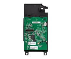
L5210 and L7000 Controls
Remove the RF Cable from the PC Board
1. Unplug the power supply from the wall outlet, an
d open
the control panel cover.
2. Release the front case from the back case by dep
ressing
the two locking tabs at the top of the unit with th
e blade of
a medium size screwdriver.
3. Disconnect the battery connector from the recept
acle on
the PC board.
Note:
Proceed to step 4 if a communications module is
already installed in the control. If this is a new
installation, proceed to step 6.
4. Remove three screws that secure the module to th
e
control.
5. Remove the module from the control and flip over
.
CELL-ANT3DB-010-V0
ROTATED
180
EXTERNAL
ANTENNA
CONNECTION
LTE-L57
SERIES
6. Locate the RF cable and slip the Antenna Cable R
emoval
Tool (p/n 700-03513) under RF Cable connector as
shown.
!
DO NOT use the tool to pry the connector loose.
Instead, pull directly upward, perpendicular to the
circuit board. Do not pull on the cable.
USE CAUTION not to damage the adjacent
components when inserting the Antenna Cable
Removal Tool.
7. Pull directly upwards until the connector detach
es from
the module’s receptacle as shown in Detail A. (This
cable
is no longer needed.)
DETAIL A
EXTERNAL
ANTENNA
CONNECTION
ANTENNA
CABLE
REMOVAL
TOOL SEE
DETAIL A
BELOW
1
3
2
Insert tool
under RF
Connector
(not wire)
Pull up
CELL-ANT3DB-009-V0
Install the CELL-EXT Adapter Cable on the PC Board
1. Connect the CELL-EXT cable to the module’s recep
tacle
as shown.
2. Holding the cable between the thumb and middle f
inger,
with the index finger on the back of the connector.
3. Align the connector vertically with the receptac
le (the
cable should be leading away from the module).
4. Gently press directly downward to mate both conn
ectors.
There should be a “snap” to confirm the mating.
5. Flip the module over and reinstall it in the pla
stic housing.
CELL-ANT3DB-011-V0
EXTERNAL
ANTENNA
CONNECTION
CELL-EXT
ADAPTER
CABLE
6. Install the module in the control. Ensure that t
he connector
board is properly seated into the receptacle on the
control
and the CELL-EXT cable is routed properly as shown.
7. Secure the module in the control with the three
screws.
8. Route the external antenna cable through the con
trol rear
case and connect the CELL-EXT cable to the WA7626-C
A
adapter cable.
9. Route the CELL-EXT cable and secure it to the ti
e wrap
point on the control with the provided tie wrap as
shown.
10. Permanently mount the external antenna.
11. Connect the battery connector to the receptacle
on the PC
board.
12. After the wiring connections are made, snap the
front and
back case closed.
13. Plug the power supply into a 24-hour, 110VAC un
switched
outlet.
TO
EXTERNAL
ANTENNA
TIE WRAP
LTE-L57
SERIES
CELL-ANT3DB-012-V0
CELL-EXT
ADAPTER
CABLE
WA7626-CA
ADAPTER
CABLE
- 4 -
L3000 Controls
Remove the RF Cable from the PC Board
1. Unplug the power supply from the wall outlet, an
d open
the control panel cover.
2. Release the front case from the back case by dep
ressing
the two locking tabs at the top of the unit with th
e blade of
a medium size screwdriver.
3. Disconnect the battery connector from the recept
acle on
the PC board.
Note:
Proceed to step 4 if a communications module is
already installed in the control. If this is a new
installation, proceed to step 7.
4. Locate the RF cable.
AUX
ANT.
LTEL3-ADT/
LTEL3V-ADT
MODULE
CELL-ADT3DB-003-V0
RF CABLE
5. Slip the Antenna Cable Removal Tool (p/n 700-035
13)
under RF Cable connector as shown.
!
DO NOT use the tool to pry the connector
loose. Instead, pull directly upward,
perpendicular to the circuit board. Do not pull
on the cable.
USE CAUTION not to damage the adjacent
components when inserting the Antenna Cable
Removal Tool.
6. Pull directly upwards until the connector detach
es from
the module’s receptacle as shown in Detail A. (This
cable
is no longer needed.)
7. Repeat step 5 and 6 to disconnect the cable from
the
module. (This cable is no longer needed.)
CELL-ANT3DB-004-V0
AUX
ANT.
DETAIL A
3
Insert tool
under RF
Connector
(not wire)
ANTENNA
CABLE
REMOVAL
TOOL SEE
DETAIL A
BELOW
1
Pull up
2
Install the CELL-EXT Adapter Cable on the PC Board
1. Connect the CELL-EXT cable to the receptacle on
the
module as shown.
2. Holding the cable between the thumb and middle f
inger,
with the index finger on the back of the connector.
3. Align the connector vertically with the receptac
le on
module (the cable should be leading away from the
module).
4. Gently press directly downward to mate both conn
ectors.
There should be a “snap” to confirm the mating.
Note:
If this is a new installation, proceed to step 5.
If a
communications module is already installed in the
control, proceed to step 8.
5. Install the module in the control.
6. Secure the module in the control with the three
screws.
(refer to the CELL-EXT Cable Routing Diagram)
7. Connect the ECP/Power Cable and Audio Cable (if
used)
to the PC board. Secure the cable(s) to the tie wra
p
point(s) on the control with the provided tie wrap(
s) as
shown. (refer to Figure 2)
8. Route the external antenna cable through the con
trol rear
case and connect the CELL-EXT cable to the WA7626-C
A
adapter cable. (The lock washer should be under the
nut.)
9. Permanently mount the external antenna.
10. Connect the battery connector to the receptacle
on the PC
board.
11. After the wiring connections are made, snap the
front and
back case closed.
12. Plug the power supply into a 24-hour, 110VAC un
switched
outlet.
AUX
ANT.
LTEL3-ADT/
LTEL3V-ADT
MODULE
CELL-ADT3DB-006-V0
TO EXTERNAL ANTENNA
ECP/POWER
CABLE
AUDIO CABLE
CONNECTOR
TIE WRAP
ECP/POWER CABLE
STRAIN
RELIEF
CLIP
NOTE
ENSURE ALL WIRING IS
ROUTED THROUGH WIRE
STRAIN RELIEF CLIP
- 5 -
LTE-X Series Communication Module
Remove the RF Cable from the PC Board
1. Power down the system, then loosen the captive c
over
screw and lift the communicator cover. Locate the R
F
cable on the module PC Board.
RF CABLE
CELL-ANT3DB-007-V0
AUX
ANT.
2. Slip the Antenna Cable Removal Tool (p/n 700-035
13)
under RF Cable connector as shown.
!
DO NOT use the tool to pry the connector
loose. Instead, pull directly upward,
perpendicular to the circuit board. Do not pull
on the cable.
USE CAUTION not to damage the adjacent
components when inserting the Antenna Cable
Removal Tool.
3. Pull directly upwards until the connector detach
es from
the module’s receptacle as shown in Detail A. Repea
t step
3 and 4 to disconnect the cable from the module PCB
.
(This cable is no longer needed.)
CELL-ANT3DB-004-V0
AUX
ANT.
DETAIL A
3
Insert tool
under RF
Connector
(not wire)
ANTENNA
CABLE
REMOVAL
TOOL SEE
DETAIL A
BELOW
1
Pull up
2
Install the CELL-EXT Cable
1. Connect the CELL-EXT cable to the receptacle on
the
PCB as shown.
2. Holding the cable between the thumb and middle f
inger,
with the index finger on the back of the connector.
3. Align the connector vertically with the receptac
le on the
PC Board.
4. Gently press directly downward to mate both conn
ectors.
There should be a “snap” to confirm the mating.
5. Route the other end of the CELL-EXT Cable throug
h the
enclosure back and connect to the WA7626-CA adapter
cable. Secure with lock washer and nut. (The lock
washer should be under the nut.) (refer to Figure 3
)
6. Permanently mount the external antenna.
7.
Power up the system and allow a few minutes for
initialization, then check the signal strength. Si
gnal LED
should be lit steady.
8. Close the front cover and secure with screw
TO
EXTERNAL
ANTENNA
CELL-ANT3DB-013-V0
CELL-EXT
ADAPTER
CABLE
WA7626-CA
ADAPTER
CABLE
- 6 -
LTEM-X Series Communication Module
Remove the RF Cable from the PC Board
1. Power down the system, then loosen the captive c
over
screw and lift the communicator cover. Locate the R
F
cable on the module PC Board.
2. Slip the Antenna Cable Removal Tool (p/n 700-035
13)
under RF Cable connector as shown.
!
DO NOT use the tool to pry the connector
loose. Instead, pull directly upward,
perpendicular to the circuit board. Do not pull
on the cable.
USE CAUTION not to damage the adjacent
components when inserting the Antenna Cable
Removal Tool.
3. Pull directly upwards until the connector detach
es from
the module’s receptacle as shown in Detail A. Repea
t step
3 and 4 to disconnect the cable from the module PCB
.
(This cable is no longer needed.)
Install the CELL-EXT Cable
4. Connect the CELL-EXT cable to the receptacle on
the
PCB as shown.
5. Holding the cable between the thumb and middle f
inger,
with the index finger on the back of the connector.
6. Align the connector vertically with the receptac
le on the
PC Board.
7. Gently press directly downward to mate both conn
ectors.
There should be a “snap” to confirm the mating.
8. Route the other end of the CELL-EXT Cable throug
h the
enclosure back and connect to the WA7626-CA adapter
cable. Secure with lock washer and nut. (The lock
washer should be under the nut.) (refer to Figure 3
)
9. Permanently mount the external antenna.
10.
Power up the system and allow a few minutes for
initialization, then check the signal strength. Si
gnal LED
should be lit steady.
11. Close the front cover and secure with screw
- 7 -
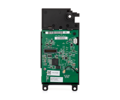
LTE-IA/LTE-IV/LTE-IC Communication Module
Remove the RF Cable from the PC Board
1. Power down the system, open the communicator cas
e by
pushing in the two bottom tabs with a screwdriver w
hile
separating the case front.
2. Locate the RF cable on the LTE-IA/LTE-IV PC Boar
d.
RF
CABLE
LTE-I SERIES
COMMUNICATOR
PCB
cell-ant3db-014-V0
3. Slip the Antenna Cable Removal Tool (p/n 700-035
13)
under RF Cable connector as shown.
!
DO NOT use the tool to pry the connector loose.
Instead, pull directly upward, perpendicular to
the circuit board. Do not pull on the cable.
USE CAUTION not to damage the adjacent
components when inserting the Antenna Cable
Removal Tool.
4. Pull directly upwards until the connector detach
es from the
module’s receptacle as shown in Detail A.
5. Tuck the disconnected antenna cable alongside th
e
battery.
cell-ant3db-019-V1
DETAIL A
3
Insert tool
under RF
Connector
(not wire)
2
1
ANTENNA
CABLE
REMOVAL
TOOL
SEE
DETAIL A
BELOW
Pull up
Install the CELL-EXT Adapter Cable
1. Connect the CELL-EXT cable to the receptacle on
the PC
Board as shown.
2. Holding the cable between the thumb and middle f
inger,
with the index finger on the back of the connector.
3. Align the connector vertically with the receptac
le on the
PC Board.
4. Gently press directly downward to mate both conn
ectors.
There should be a “snap” to confirm the mating.
5. Route the other end of the CELL-EXT Cable throug
h- the
enclosure back and connect to the WA7626-CA adapter
cable. Secure with lock washer and nut. (The lock
washer should be under the nut.) (refer to Figure 4
)
6. Permanently mount the external antenna.
7. Power up the system and allow a few minutes for
initialization, then check the signal strength. Si
gnal LED
should be lit steady.
8. Close the front cover and secure with screw.
LTE-I SERIES
COMMUNICATOR
PCB
TUCK THE
DISCONNECTED
ANTENNA CABLE
ALONGSIDE
THE BATTERY
UNDER THE
RETAINER
cell-ant3db-015-V1
TO
EXTERNAL
ANTENNA
CELL-EXT
ADAPTER
CABLE
WA7626-CA
ADAPTER
CABLE
Specifications
Frequency & Cellular Bands Supported
: ............... 698 - 960 MHz, Bands: 5, 6, 8, 1
2, 13, 14, 17, 18, 19, 20, 26, 27, 28, 29, 67, 68,
85
..................................................
...................................................
........ 1710 - 2700 MHz, Bands: 1, 2, 3, 4, 7, 9,
10, 25, 30, 65, 66, 69, 70
Cellular Networks
: ................................................
...................................................
..................................... LTE, WCDMA, C
DMA, GSM
Peak Gain:
..................................................
...................................................
...................................................
................................... 3dBi
Maximum power:
..................................................
...................................................
...................................................
......................... 30W
Nominal impedance:
..................................................
...................................................
...................................................
............ 50 ohms
Pattern:
..................................................
...................................................
...................................................
.................... Omni Directional
Termination:
.................................................
...................................................
...................................................
........................ N Female
Operating Temperature
: .................................................
...................................................
.........................
-22° to 158°F (-30ºC to 70ºC)
Fully Weatherproof for Outdoor Application
Dimensions:
...................................................
...................................................
...................................................
.................. 1.05” x 11.8”
VSWR:
..................................................
...................................................
...................................................
......................................... <3:1
Random Material:
..................................................
...................................................
...................................................
... Fiberglass, White
Polarization:
...................................................
...................................................
...................................................
.......................... Vertical
FEDERAL COMMUNICATIONS COMMISSION & INDUSTRY CANADA
STATEMENTS
The user shall not make any changes or modification
s to the equipment unless authorized by the Install
ation Instructions or User's Manual. Unauthorized
changes or modifications could void the user's auth
ority to operate the equipment.
FCC CLASS B STATEMENT
This equipment has been tested to FCC requirements
and has been found acceptable for use. The FCC requ
ires the following statement for your
information:
This equipment generates and uses radio frequency e
nergy and if not installed and used properly, that
is, in strict accordance with the manufacturer's
instructions, may cause interference to radio and t
elevision reception. It has been type tested and fo
und to comply with the limits for a Class B computi
ng
device in accordance with the specifications in Par
t 15 of FCC Rules, which are designed to provide re
asonable protection against such interference in a
residential installation. However, there is no guar
antee that interference will not occur in a particu
lar installation. If this equipment does cause inte
rference
to radio or television reception, which can be dete
rmined by turning the equipment off and on, the use
r is encouraged to try to correct the interference
by
one or more of the following measures:
• If using an indoor antenna, have a quality outdoo
r antenna installed.
• Reorient the receiving antenna until interference
is reduced or eliminated.
• Move the radio or television receiver away from t
he receiver/control.
• Move the antenna leads away from any wire runs to
the receiver/control.
• Plug the receiver/control into a different outlet
so that it and the radio or television receiver ar
e on different branch circuits.
• Consult the dealer or an experienced radio/TV tec
hnician for help.
INDUSTRY CANADA CLASS B STATEMENT
This Class B digital apparatus complies with Canadi
an ICES-003.
Cet appareil numérique de la classe B est conforme
à la norme NMB-003 du Canada.
FCC / IC STATEMENT
This device complies with Part 15 of the FCC Rules,
and Industry Canada’s License-exempt RSSs. Operati
on is subject to the following two conditions: (1)
This device may not cause harmful interference (2)
This device must accept any interference received,
including interference that may cause undesired
operation.
Cet appareil est conforme à la partie 15 des règles
de la FCC et exempt de licence RSS d’Industrie Can
ada. Son fonctionnement est soumis aux
conditions suivantes: (1) Cet appareil ne doit pas
causer d’interférences nuisibles. (2) Cet appareil
doit accepter toute interférence reçue y compris le
s
interférences causant une réception indésirable.
The product should not be disposed of with other ho
usehold waste. Check for the nearest authorized col
lection centers or authorized
recyclers. The correct disposal of end-of-life equi
pment will help prevent potential negative conseque
nces for the environment and
human health.
RF EXPOSURE
Warning
- The internal or external antenna(s) used with thi
s product must be installed to provide a separation
distance of at least 7.8 in.
(20 cm) from all persons and must not be co-located
or operating in conjunction with any other antenna
or transmitter except in
accordance with FCC multi-transmitter product proce
dures.
Mise en Garde
Exposition aux Fréquences Radio:
L'antenne (s) utilisée pour cet émetteur doit être
installée à une distance de séparation d'au moins
7,8 pouces (20 cm) de toutes les personnes.
IMPORTANT NOTES ABOUT EXTERNAL ANTENNAS
•
If an external cellular radio antenna is used, the
antenna may be installed or replaced ONLY by a pro
fessional installer.
•
The directional gain of any antenna must not excee
d the limits specified by the FCC for the type appr
oved radio module.
DOCUMENTATION, SUPPORT AND WARRANTY INFORMATION
Refer to the installation and setup guide for the c
ontrol with which this device is used for warranty
information and limitations of
the entire system.
For documentation and online support: www.resideo.c
om
This product is manufactured by Resideo Technologie
s, Inc. and its affiliates.
2 Corporate Center Drive, Suite 100
P.O. Box 9040, Melville, NY 11747
© 2020 Resideo Technologies, Inc.
www.resideo.com
ÊR800-26571A$Š
R800-26571A 11/20 Rev. A
- Uploaded