Installing a Honeywell 7847i on a VISTA-15 P, VISTA-20P, VISTA-21iP Alarm Panel
Related Products


Description
Installing a Honeywell 7847i on a VISTA P-Series Panel
Transcript
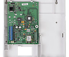
Hi DIYers, this is Michael from Alarm Grid. And today I'm going to be showing you how to install a Honeywell 7847i-- seven eight four seven i-- to a Honeywell VISTA P-series security system. Now, the VISTA P-series systems, at least most of them, the 15p, the 20p, they don't have a built-in communicator. The 21iP is an exception in that it does have a built in IP communicator, so you wouldn't add this to a 21iP most likely, but VISTA-15p or a VISTA-20p, they're both panels that you would certainly add the Honeywell 7847i to. So what the Honeywell 7847i is, it's an IP only communicator. It allows the panel to communicate across an internet network, to communicate with the AlarmNet servers. And that's needed for monitoring service, and for access to Total Connect 2.0, which is a remote platform for controlling your system remotely. So you will need monitoring service to activate this communicator. And the advantage to going with an IP only communicator is that you will typically be able to get the lowest cost monitoring plans, because you'll be able to just get an IP only plan. This is opposed to getting a cellular plan, which will include cellular service. You would need a cellular communicator to use one of those plans, which this is not a cellular communicator. This is just IP only. But the drawback to using IP only is that in the event of an internet outage, if a power outage takes your router offline, and you don't have a backup power source for your router, then your panel will be unmonitored. So if you're prone to power outages, or internet outages, keep that in mind and consider going with cellular. But if you're comfortable having your home or business monitored through IP only, and you're looking for a low cost monitoring plan, then using the Honeywell 7847i with your VISTA P-series security system is certainly a great option. And just remember, to get Total Connect 2.0 for VISTA-15p or 20p, you will need the PROM chip version 9.12, or higher. We have ours here. This is a PSI panel, so it's approved by the Security Industry Association. And this is-- it looks like 10.23. So that is high enough. It's above 9.12 for the VISTA-20p, or 15p. So this can do Total Connect 2.0. So now it's just a matter of wiring it up, and powering it on. So we're going to take a look at the four-wire connection that goes from the communicator to the panel. We'll show you what each wire means, and then we'll go and wire it up and power it on. So like I said, the Honeywell 7847i uses a four-wire connection with the panel. It gets all its power from the panel. It doesn't have its own transformer or a backup battery, so it's just drawing power from the panel. It draws 75 milliamps of current at maximum usage. So make sure to calculate that into the power draw calculation. Make sure to consider that. If you're going over, then you will need to add an external power supply or something. So like I said, it's a four-wire connection. We're using 22 gauge four conductor wire. 18 gauge also works fine. Really, whatever you have around. And we like to make our wire color coded, so that way we know where everything goes. But really, color isn't super important as long as the wires match at the communicator and the panel. But I'll be talking based on the color coded just to stay organized here. So first, we have our red wire for positive power. And this goes at panel terminal 5 and communicator terminal 3. And then, we have the black wire for the negative connection, the negative power, or the ground connection. This goes to panel terminal 4 and communicator terminal 4. And then we have the yellow or white wire. In our case, it's a white wire. And this is for data to the communicator. So it's the panel speaking to the 7847i. And this goes to panel terminal 7 and communicator terminal 5. And lastly, we have our green wire for data to the panel. So this is the 7847i communicating to the panel. And it goes to panel terminal 6 and communicator terminal 6. So those are the four wires. Just again to recap, the red goes to panel terminal 5 and communicator terminal 3. The black wire goes to panel terminal 4 and communicator terminal 4. The yellow or the white wire goes to panel terminal 7 and communicator terminal 5. And the green wire goes, panel terminal 6 and communicator terminal 6. So those are the four wires you will use with the 7847i. So now we're doing our four-wire connection at the communicator. You can see our first two terminals have been removed. So we're starting at terminal 3. This is for the red wire, the positive power. And we're using that 22 gauge, four conductor wiring. You can use pretty much whatever you have around. But this works well for us. And it's stranded wire here. Then we got the black wire going into terminal 4. And this is for the ground connection, the negative power here. And then we got the yellow, or in our case the white wire going into terminal 5. And this is for data to the communicator. So it's the panel speaking to the communicator, speaking to the 7847i. Lastly, we got our green wire going into terminal 6. And this is for communication to the panel. So it's for when the communicator needs to speak to the panel in the 7847i, goes to the panel. Got all four connections secure, and we're good to go at the communicator. So now we'll be connecting the wires at the panel. And just reminder, make sure your panel is completely powered down. You can see that ours is-- the transformer is unplugged because we have the Honeywell LT-Cable with the barrel connection unplugged. And also make sure the battery is disconnected, which we have our flying leads that are disconnected there. So we're going to go in order on the panel here. And we're starting at terminal 4 for the black wire. This is the negative power connection. Terminal 4 for the black wire. That's good. Then terminal 5 is for the red wire, for positive power. All right. Then we got terminal 6 for the green wire. This is data to the panel. So it's the communicator speaking to the panel using the green wire. And then last but not least, we got the yellow, or in our case the white wire going to terminal 7. And this is for communication to the 7847i. So it's the panel speaking to the communicator. These are the same locations where you would put your keypads, but we don't have any keypads, so this is just for demonstration. And you see our connections are good. And we've wired the communicator to the panel. So now that our connections are made between the 7847i and the VISTA-20p, we can go ahead and power our system back on. We have our Honeywell LT-Cable, the barrel connection. We're just going to plug it in. And you can see the lights on the communicator illuminate, indicating that the panel is providing power to the communicator. We don't have any keypad set up with our VISTA-20p, but if you did, then they would power on as well. But you'll just have to trust us that it is powered on. It is powering the communicator. So just a few little tidbits I want to leave you with before we end this video. I want to point out that the 7847i gets its network connection using an ethernet cable. You have to run an ethernet cable from your router to the module, the 7847i. You run it through the back plate. And you're going to bend it at an awkward angle so it can connect to the ethernet port right here. It is normal. You do bend it at an abrupt angle. It will look a little weird, but that's perfectly fine, how it's supposed to be. One option if you don't want to have to run an ethernet cable all the way from your router to the 7847i is to use an ethernet to Wi-Fi bridge. Like the alarm.com ADC-W110. This will allow you to connect an ethernet wire between the communicator and the ADC-W110, or whatever ethernet to Wi-Fi bridge you are using. And then you will interface this with your router, and it will communicate wirelessly. So it essentially converts this wired connection into a wireless connection to give you more flexible installation options. You will still need to run the ethernet cable between the two, but you can have that right by the device. And you will need to plug this into an outlet, so keep that in mind. And one last thing, make sure to note the MAC and MAC/CRC codes on the Honeywell 7847i. You will need to provide this to your monitoring company when you go to activate the communicator. This is important information. We recommend either writing down this information, and keeping it somewhere safe, or taking a picture of it and storing it somewhere. So that way, you won't have to open up the cover of the module to access the information. We have ours already opened up, but usually you will have this closed with a cover. So that's how you install a Honeywell 7847i to a Honeywell VISTA P-series security system. If you have any questions about the Honeywell 7847i, or about Honeywell VISTA systems, or about alarm monitoring, send an email to support@alarmgrid.com. If you we found this video helpful, make sure to give it a thumbs up below to like the video. And remember to subscribe to our channel for updates on future videos. We hope you enjoy the video. Thank you.
- Uploaded