Honeywell L5100 Programming Guide (Rev 5)
Related Products

Related Categories
Document Transcript
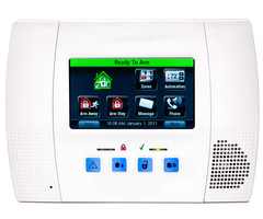
LYNX Touch
Security System
Programming Guide
800-11060 2/12 Rev. A
Table of Contents
Entering Programming Mode......................................................................................................
.............................. 3
Programming the Data Fields....................................................................................................
............................... 3
Loading a Default Set ..........................................................................................................
..................................... 3
Exiting Programming Mode .......................................................................................................
............................... 3
Data Fields....................................................................................................................
............................................ 4
Change Installer Code........................................................................................................................................... 4
Program System Type............................................................................................................
............................... 4
Program Date and Time ..........................................................................................................
.............................. 5
Program Communications.........................................................................................................
............................ 5
Program Zones..................................................................................................................
.................................... 7
Program Keys...................................................................................................................
..................................... 8
Program Reporter...............................................................................................................
................................... 9
Program Sounder ................................................................................................................
................................ 13
Program System Settings........................................................................................................
............................ 14
Program the Z-Wave Module ......................................................................................................
........................ 16
Zone Programming Worksheet .....................................................................................................
......................... 17
Explanation of Zone Assignment Table Headings ..................................................................................
............ 18
5800 Series Transmitter Loop Numbers Diagram...................................................................................
............... 19
Programming Default Tables.....................................................................................................
............................. 20
LYNX Touch Summary of Connections Diagram ......................................................................................
............. 23
Refer to the LYNX Touch Series Installation and Setup Guide P/N 800-10614 or later for detailed information on
programming the system. The Installation and Setup Guide contains full descriptions for all data fields.
UL
LYNX Touch is not intended for UL985 Household Fire applications unless a 24-hour backup
battery (P/N LYNXRCHKIT-SHA) is installed.
- 3 -
Entering Programming Mode
You may find it convenient to adjust the volume setting before entering the Programming Mode. This
will allow you to clearly hear feedback announcements or system beeps.
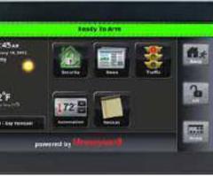
1. Power up the LYNX Touch control, when the Home Screen appears, select “More”.
2. Select “Tools”. The system displays a virtual keypad.
3. Enter: Installer Code (4 + 1 + 1 + 2).
4. The System Programming Screen is displayed. Select “Program”. The Armed and Ready LEDs will flash and
the following options will be displayed:
Installer Code
Date Time
Zones
Keys
System Type
Communicator
Comm. Diagnostics
Reporter
Use the down
T
arrow to scroll to the next page of options.
Sounder
Default Config.
Reset Master Code
System Settings
Language*
Z-Wave
* This field may not be applicable to the system being installed.
5. Select an option to advance to that Programming screen.
Note:
If a different Installer Code has been programmed, enter: the New Installer Code.
Programming the Data Fields
1. Select each desired programming option, and then select the required entry. The system beeps each time a
selection is made.
2. The system will toggle or scroll through the options or display a new screen as required for the specific
option.
3. To delete or change an entry, simply select the desired option, and then select the required entry.
Loading a Default Set:
1. Enter the Installer Programming Mode and advance to second page of the System Programming.
2. Select ‘Default Config’ and select the appropriate Default Table Configuration from the following options or
Select Default Downloader to reset all subscriber account numbers and CSID in preparation for an initial
download:
Default Config 1
Default Config 2
Default Config 3
Default Config 4
Default Downloader
Note:
Refer to the Programming Default Tables section of this manual to view the default values.
Exiting Programming Mode:
1. Select the “
2
” key to exit the current screen. The system returns to the previous screen.
2. Select the “
2
” key as required until system displays a Confirmation screen.
3. Select “Yes” to allow the installer to re-enter Programming mode or “No” to prevent re-entry. If “No” is
selected, you can still re-enter Program Mode by powering down the unit (remove AC and battery power) and
entering Program Mode within 30 seconds of powering up.
4. Select the “
2
” key again to return to the Home Screen. Screen Display
Function & Programming Options
- 4 -
DATA FIELDS
Note:
If applicable, preprogrammed defaults for the LYNX Touch Control are shown on the screen display.
Change Installer Code
5000-100-129-V0
Installer Code
Installer Code
Enter 4 digits [The defaulted Installer Code is 4112]
0-9
Program System Type
RF Jam
Disabled
RF Jam
Disabled
Enabled
Speaker Phone
Enabled
Speaker Phone
Disabled
Enabled
Two Way Voice
Disabled
Two-Way Voice
Disabled
Enabled
RF House Code
0
RF House Code
Enter 2 digits, 00-31
Phone Notification
Disabled
Phone Notification
Disabled
Keypad
Trouble
Note:
If “Keypad” or “Trouble” is selected you will be prompted to program a phone detect time.
Phone Detect Time
2 Minutes
Phone Detect Time
1 Minute
2 Minutes
3 Minutes
4 Minutes
Remote Phone
Enabled
Remote Phone
Disabled
Enabled
Events - Log All
Press To Log All
Events – Log All
Note:
If Press to Log All is selected the system will log the following events:
Alarm
Bypass
Open/Close
Trouble
Non-Security
Events – Log Alarm
Enabled
Events – Log Alarm
Enabled
Disabled
Events – Log Bypass
Disabled
Events – Log Bypass
Enabled
Disabled
Events – Log Open
Close
Disabled
Events - Log Open/Close
Enabled
Disabled
Events – Log Trouble
Enabled
Events – Log Trouble
Enabled
Disabled
Non Security
Disabled
Non Security
Enabled
Disabled
Remote Access Serial
Disabled
Remote Access Serial
Enabled
Disabled
Note:
If the “Remote Access Serial” option is enabled, you will be prompted to select a “Multi Mode Serial”. Screen Display
Function & Programming Options
- 5 -
Multi Mode Serial
Disabled
Multi Mode Serial
Enhanced Reports
Disabled
Program Date and Time
5000-100-131-V0
Date Time
Date Time
Note:
If you are installing a GSMVLP5 or ILP5 Communication Module, the time and date will be
programmed and updated automatically via Central Station. You must still program the correct
Time Zone below.
1. Month and Year
2. Select the correct date
3. Enter the correct time
4. Select AM or PM
5. Select Save or continue below.
Time Zone
Eastern (EST)
Time Zone
Eastern (EST)
Mountain (MST)
Atlantic (AST)
Central (CST)
Pacific (PST)
Newfoundland (NT)
Hawaii (HAST)
Alaska (AKST)
Day Light Savings Time
Yes
Day Light Savings Time
Yes
No
Note:
If Yes is selected, the following options will be active.
Start Month
March
Start Month
January July
February August
March September
April October
May November
June December
Start Week
Second
Start Week
First
Second
Third
Fourth
Last
Next to Last
3rd from Last
End Month
November
End Month
January July
February August
March September
April October
May November
June December
End Week
First
Start Week
First
Second
Third
Fourth
Last
Next to Last
3rd from Last
Program Communications
5000-100-132-V0
Communicator
Communicator
Program the following options:
Communications Path
APL
City ID
CS ID
Sub ID
Supervision
Old Alarm Time
Remote Acc. Comm.
Multi Mode Comm.
GSM Fault Time OR
IP Fault Time
Screen Display
Function & Programming Options
- 6 -
Communications Path
None
Communications Path
None
IP
GSM
WiFi
WiFi & GSM
APL
Disabled
Advanced Protection Logic
Enabled
Disabled
City ID
Primary City Identification
Enter 2 digits
01-99
CS ID
Primary Central Station Identification
Enter 2-digits (HEX)
01-FE
Sub ID
Primary Subscriber Identification
Enter 4-digits
0001-9999
Supervision
24 Hours
Supervision
24 Hours
None
30 Days
Old Alarm Time
10 Minutes
Old Alarm Time
10 Minutes
15 Minutes
30 Minutes
1 Hour
2 Hours
4 Hours
8 Hours
12 Hours
24 Hours
Remote Acc. Comm.
Disabled
Remote Access Communication
Disabled
Enabled
Note:
If enabled the following option will be active.
Multi Mode Comm.
Disabled
Multi Mode Communication
Disabled
Relay Reports
Enhanced Reports
GSM Fault Time (min)
00
GSM Fault Time (min)
(displayed if GSM is selected as Communications Path)
Enter 2-digits
00-99
IP Fault Time
(min)
00
IP Fault Time (min)
(displayed if IP is selected as Communications Path)
Enter 2-digits
00-99
Use DHCP
Yes
Use DHCP
Note:
If disabled the following options will be active.
Yes
No
NIC IP Address
255.255.255.255
IP Fault Time
Enter 4 part address
Subnet Mask
255.255.255.255
Subnet Mask
Enter 4 part address
Gateway IP Address
255.255.255.255
Gateway IP Address
Enter 4 part address
DNS Server IP Address
255.255.255.255
DNS Server Address
Enter 4 part address
Screen Display
Function & Programming Options
- 7 -
Program Zones
5000-100-133-V0
Zones
Zones
Select from the following zone options:
1. New
3. Back Door
5. Motion Sensor
7. – 48. New
49. – 56. 4 Button
57. – 64. New
80. – 85. Temperature
95. Fire
96. Medical
99. Police
2. Front Door
4.Window
6.New
Select a zone and then select “Edit” or “Add New” to program the next available zone.
Program the following options:(dependent upon Zone Type):
Serial Number
Loop Number
Zone Description 1
Zone Description 2
Device Type
Response Type
Report Chime Supervision
Serial Number
Serial Number
When “Serial Number” has been selected “Enter Serial Number or Activate” is displayed.
The transmitter serial number and loop number can be enrolled via RF transmission OR
manually.
Enroll via RF Learning
To enroll the device using RF Learning mode three transmissions
(open/close) of the device will be required. The initial transmission activates the RF
Learning mode and the system will emit a single beep. A second transmission enrolls the
serial number and the system beeps two times and displays “Activate Sensor Again To
Confirm”. A third transmission will confirm the serial number. The system beeps two times
and returns to the Zone programming Screen.
Enroll Manually
Enter the 7-digit serial number printed on the transmitter using the displayed keypad and
select “Done”. The system beeps one time and returns to the Zone programming Screen.
Loop Number
1
Loop Number
1, 2, 3 or 4
Zone Description 1
Zone Description 2
Zone Description 1
The system announces the Zone Description. If desired, enter a zone descriptor.
Zone Description 2
The system announces the Zone Description. If desired, enter a zone descriptor.
Device Type
Device Type
Choose from the following options (dependant upon the Device Type):
New Door
Window Motion
Sensor
Glass Break
Smoke Detector
Heat Sensor
Carbon Mono. Det.
Temperature Flood
Environmental Medical
Fire
Police
Other
Response Type
Not Used
Response Type
Choose from the following options (dependant upon the Zone):
Not Used
Arm Stay
Fire No Verification
Entry Exit 1
Disarm
Monitor
Entry Exit 2
Silent Burglary
Trouble
Interior Follower
Resident Response
Arm Away
24 Hour Silent
General Response
No Response
24 Hour Auxiliary
Perimeter
Resident Monitor
Interior With Delay
Day/Night
General Monitor
Carbon Monoxide
24 Hour Audible
Fire With Verification
Report
Yes
Report
Yes
No Screen Display
Function & Programming Options
- 8 -
Chime
No
Chime
Yes
No
Supervision
Supervised
Supervision
Hardwire Zone
Normal Open
Normal Closed
End of Line
RF Zone
Supervised
Unsupervised
Temperature
High Temp
Low Temp
Program Keys
Keys
Keys
Select from the following options:
Edit Add
New Delete
If add new is selected the following options can be programmed:
Key Type
User
Serial Number
Zone
Button Key 1 – Zn 49
Button Key 2 – Zn 50
Button Key 3 – Zn 51
Button Key 4 – Zn 52
Button Key 5 – Zn 53
Button Key 6 – Zn 54
Button Key 7 – Zn 55
Button Key 8 – Zn 56
Key Type
4 Button Key
Key Type
1 Button Key.
2 Button Key
4 Button Key
6 Button Key
8 Button Key
User
User
Master
Duress
Babysitter
User 3 through User 14
Note:
The Key must be associated with a specific User/User Code in order for it to operate. Refer to the
LYNX Touch User Guide for additional Information regarding User Codes.
Serial Number
0
Serial Number
When “Serial Number” has been selected “Enter Serial Number or Activate” is displayed.
The transmitter serial number and loop number can be enrolled via RF transmission OR
manually.
Enroll via RF Learning
To enroll the device using RF Learning mode three transmissions
(open/close) of the device will be required. The initial transmission activates the RF
Learning mode. A second transmission enrolls the serial number and the system beeps two
times and displays “Activate Sensor Again To Confirm”. A third transmission will confirm the
serial number. The system beeps two times and returns to the Zone programming Screen.
Enroll Manually
Enter the 7-digit serial number printed on the transmitter using the displayed keypad and
select “Done”. The system beeps one time and returns to the Zone programming Screen
Zone
49
Zone
Manually enter a specific two-digit Zone Number (49-64).
Button Key * - Zone *
Button Key * Zn *
Enter a function for each button key from the following options:
Disarm Arm Away
Arm Stay
No Response
24 Hour Silent
24 Hour Audible
24 Hour Auxiliary
Silent Burglary
Fire No Verification
* Options are the same for each Button/Zone combination.
Screen Display
Function & Programming Options
- 9 -
Program Reporter
Reporter
Reporter
Program the following options:
Primary CS Info
Secondary CS Info
Follow Me Phone 1
Follow Me Phone 2
Report Selection
Options
Downloader
Primary CS Info
Primary Central Station Information
Phone Type
Communicator Type
Phone Type
Contact Id: 4 Digit
Phone Type
None
Contact Id : 4 Digit
Contact Id : 10 Digit
SIA
Note:
If SIA, Contact Id: 4 Digit, or Contact Id: 10 Digit is selected the Phone Number and Account
Number options will be displayed.
Communicator Type
None
Communicator Type
None
GSM
WiFi
WiFi & GSM
IP
Note:
If IP is selected the Dynamic Priority option will be displayed.
Phone Number
Phone Number
Enter the Primary Central Station Phone Number (Up to 20 digits)
Account Number
FFFF
Account Number
Enter the Primary Central Station Account Number
Dynamic Priority
Dynamic Priority
Redundant Reports
Preferred Telco
Preferred Radio
Note:
If Preferred Telco or Preferred Radio is selected the Dynamic Delay option will be displayed.
Dynamic Delay
Dynamic Delay
15 Seconds
30 Seconds
60 Seconds
90 Seconds
Report All
Press to Report All
Report All
Press to Report All
Report All Set
Report Alarms
Enabled
Report Alarms
Disabled
Enabled
Report Troubles
Enabled
Report Troubles
Disabled
Enabled
Report Open/Close
Disabled
Report Open/Close
Disabled
Enabled
Report Tests
Enabled
Report Tests
Disabled
Enabled
Secondary CS Info
Secondary Central Station Information
Phone Type
Communicator Type
Phone Type
None
Phone Type
None
Contact Id: 4 Digit
Contact Id: 10 Digit
SIA
Note:
If SIA, Contact Id: 4 Digit or Contact Id: 10 Digit is selected, the Phone Number and Account
Number options will be displayed.
Screen Display
Function & Programming Options
- 10 -
Communicator Type
None
Communicator Type
None
GSM
WiFi
WiFi & GSM
IP
Note:
If IP is selected the Dynamic Priority option will be displayed.
Phone Number
Phone Number
Enter the Secondary Central Station Phone Number (Up to 20 digits)
Communicator Type
None
Communicator Type
None
GSM
IP
Note:
If IP is selected the Dynamic Priority option will be displayed.
Phone Number
Phone Number
Enter the Secondary Central Station Phone Number
Account Number
FFFF
Account Number
Enter the Secondary Central Station Account Number
Dynamic Priority
None
Dynamic Priority
Redundant Reports
Preferred Telco
Preferred Radio
Note:
If Preferred Telco or Preferred Radio is selected the Dynamic Delay option will be displayed.
Dynamic Delay
None
Dynamic Delay
None
15 Seconds
30 Seconds
60 Seconds
90 Seconds
Report All
Press to Report All
Report All
Press to Report All
Report All Set
Report Alarms
Enabled
Report Alarms
Disabled
Enabled
Report Troubles
Disabled
Report Troubles
Disabled
Enabled
Report Open/Close
Disabled
Report Open/Close
Disabled
Enabled
Report Tests
Enabled
Report Tests
Disabled
Enabled
Follow Me Phone 1
Follow Me Phone 1
Choose from the following options:
Phone Type
Phone Number
Report All
Report Alarms
Report Troubles
Report Open/Close
Report Tests
Phone Type
None
Phone Type
None
Follow me
Phone Type
None
Phone Number
Enter the Follow Me Phone Number
Report All
Press to Report All
Report All
Press to Report All
Report All Set Screen Display
Function & Programming Options
- 11 -
Report Alarms
Disabled
Report Alarms
Disabled
Enabled
Report Troubles
Disabled
Report Troubles
Disabled
Enabled
Report Open/Close
Disabled
Report Open/Close
Disabled
Enabled
Report Tests
Disabled
Report Tests
Disabled
Enabled
Follow Me Phone 2
Follow Me Phone 2
Choose from the following options:
Phone Type
Phone Number
Report All
Report Alarms
Report Troubles
Report Open/Close
Report Tests
Phone Type
None
Phone Type
None
Follow me
Phone Number
Phone Number
Enter the Follow Me Phone Number
Report All
Press to Report All
Report All
Press to Report All
Report All Set
Report Alarms
Disabled
Report Alarms
Disabled
Enabled
Report Troubles
Disabled
Report Troubles
Disabled
Enabled
Report Open/Close
Disabled
Report Open/Close
Disabled
Enabled
Report Tests
Disabled
Report Tests
Disabled
Enabled
Report Selection
Report Selection
Choose from the following options:
Arm Away
Arm Stay
Bypass
Low Battery Restore
Disarm
Exit Error
AC Loss
RF Low Battery Restor
Recent Closing
Event Log Full
Low Battery
Trouble
Trouble Restore
RF Low Battery
Alarm Restore
Alarm Cancel
Bypass Restore
Test
Test Restore
AC Loss Restore
Arm Away
Enabled
Arm Away
Disabled
Enabled
Arm Stay
Enabled
Arm Stay
Disabled
Enabled
Disarm
Enabled
Disarm
Disabled
Enabled
Exit Error
Enabled
Exit Error
Disabled
Enabled
Recent Closing
Enabled
Recent Closing
Disabled
Enabled Screen Display
Function & Programming Options
- 12 -
Event Log Full
Enabled
Event Log Full
Disabled
Enabled
Trouble
Enabled
Trouble
Disabled
Enabled
Trouble Restore
Enabled
Trouble Restore
Disabled
Enabled
Alarm Restore
Enabled
Alarm Restore
Disabled
Enabled
Alarm Cancel
Enabled
Alarm Cancel
Disabled
Enabled
Test
Enabled
Test
Disabled
Enabled
Test Restore
Enabled
Test Restore
Disabled
Enabled
Bypass
Enabled
Bypass
Disabled
Enabled
Bypass Restore
Enabled
Bypass Restore
Disabled
Enabled
AC Loss
Enabled
AC Loss
Disabled
Enabled
AC Loss Restore
Enabled
AC loss Restore
Disabled
Enabled
Low Battery
Enabled
Low Battery Restore
Disabled
Enabled
Low Battery Restore
Enabled
Low Battery Restore
Disabled
Enabled
RF Low Battery
Enabled
RF Low Battery
Disabled
Enabled
RF Low Battery Restore
Enabled
RF Low Battery Restore
Disabled
Enabled
Options
Options
Choose from the following options:
PBX
Call Wait Cancel
Number of Reports
Alarm Report Delay
First Report Offset
Report Frequency
PBX
PBX
Enter PBX Prefix
Call Wait Cancel
Call Wait Cancel
Enter Call Wait Cancel Prefix
Number of Reports
Unlimited
Number of Reports
Unlimited
10 Reports Screen Display
Function & Programming Options
- 13 -
Alarm Report Delay
No Delay
Alarm Report Delay
No Delay
15 Sec.
30 Sec.
45 Sec.
First Report Offset
6 Hrs
First Report Offset
6 Hrs
12 Hrs
18 Hrs
24 Hrs
Report Frequency
Never
Report Frequency
Never
Every Day
Every 7 Days
Every 30 Days
Downloader
Downloader
Choose from the following options:
Phone Answer
Modem Speed
Ans. Machine Defeat
Callback Number
Ring Counter
Flexible Callback
Number
Phone Answer
Yes
Phone Answer
Yes
No
Modem Speed
Slow
Modem Speed
(Future Use)
Ans. Machine Defeat
Yes
Answering Machine Defeat
Yes
No
Callback Number
Yes
Callback Number
Enter a Callback Number
Ring Counter
2
Ring Counter
(displayed if Ans. Machine Defeat is set to “No”)
Enter ring counter (1-14)
Flexible Callback
No
Flexible Callback
Yes
No
Number
Number
(displayed if Flexible Callback is set to “Yes”)
Enter the number of flexible callbacks that will be used (1-3)
Program Sounder
Sounder
Sounder
Choose from the following options:
Burglary Alarm Sound
Burglary Bell Timeout
Fire Bell Timeout
Arm Confirm
Alarm Options
Burglary Alarm Sound
Yes
Burglary Alarm Sound
Yes
No
Burglary Bell Timeout
4 Minutes
Burglary Bell Timeout
No
4 Minutes
8 Minutes
12 Minutes
16 Minutes
Fire Bell Timeout
4 Minutes
Fire Bell Timeout
No
4 Minutes
8 Minutes
12 Minutes
16 Minutes
Screen Display
Function & Programming Options
- 14 -
Arm Confirm
None
Arm Confirm
None
All RF
RF Key Fob
RF Keypad
Alarm Options
Unlimited
Alarm Options
Unlimited
1
2
10
Program System Settings
System Settings
System Settings
Choose from the following options:
Entry Delay 1
Entry Delay 1
Exit Delay
Backlight Timeout
Quick Arm
Quick Exit
Restart Exit Time
Force Bypass Exit Warning
Auto Stay Arming
Lack of Usage Notify
Power-up in Previous
Display Alarm Cancel
Display Exit Time
Cross Zone Delay
Cross Zone 1
Cross Zone 2
Entry Delay 1
30 Seconds
Entry Delay 1
None
15 Seconds
30 Seconds
4
5 Seconds
60Seconds
90 Seconds
2
Minutes
Entry Delay 2
30 Seconds
Entry Delay 2
None
15 Seconds
30 Seconds
4
5 Seconds
60Seconds
90 Seconds
2
Minutes
Exit Delay
30 Seconds
Exit Delay
None
15 Seconds
30 Seconds
45 Seconds
60Seconds
90 Seconds
2 Minutes
Backlight Timeout
No
Backlight Timeout
No
30 Seconds
Quick Arm
Yes
Quick Arm
Yes
No
Quick Exit
No
Quick Exit
Yes
No
Restart Exit Time
No
Restart Exit Time
Yes
No
Force Bypass
No
Force Bypass
Yes
No
Screen Display
Function & Programming Options
- 15 -
Exit Warning
No
Exit Warning
Yes
No
Auto Stay Arming
No
Auto Stay Arming
Yes
No
Lack of Usage Notify
Disabled
Lack of Usage Notify
Disabled
1 Day
7 Days
27 Days
90 Days
180 Days
365 Days
Power-Up in Previous
Yes
Power-Up in Previous State
Yes
No
Display Alarm Cancel
No
Display Alarm Cancel
Yes
No
Display Exit Time
Yes
Display Exit Time
Yes
No
Cross Zone Delay
3 Minutes
Cross Zone Delay
None
30 Seconds
1 Minute
90 Seconds
2 Minutes
3 Minutes
4 Minutes
Cross Zone 1
Disabled
Cross Zone 1
Disabled
Cross Zone 2
Disabled
Cross Zone 2
Disabled
Screen Display
Function & Programming Options
- 16 -
Program the Z-Wave Module
5100-100-067-V0
Z - Wave
Z-Wave
Note:
This procedure must be completed any time that the panel has been defaulted or
updated.
Z-Wave
Enabled-Installed Telephone
Z-Wave
Select from the following options:
Enabled – Installed Telephone Side
Disabled
Temperature Display
Fahrenheit
Temperature Display
Select from the following options:
Fahrenheit
Celsius
- 17 -
Zone Programming Worksheet
Fill in the required data on this worksheet, then follow the programming procedure.
See Explanation of Zone Assignment Table Headings
(defaults shown are for Table 1)
Zone
No.
Loop
No.
Device
Type
Response
Type Report Chime
Supervision
Transmitter
Serial Number
Zone
Descriptor
1
N/A
New
N/A
Yes
No
End of Line
N/A
(HW Zone)
2
2
Door
Entry Exit 1
Yes
Yes
RF Supervised
Front Door
3
2
Door
Entry Exit 1
Yes
Yes
RF Supervised
Back Door
4 2 Window Perimeter Yes Yes RF Supervised
5
1
Motion Sensor
Interior w/Delay
Yes
No
RF Supervised
6
7
8
9
10
11
12
13
14
15
16
17
18
19
20
21
22
23
24
25
26
27
28
29
30
31
32
33
34
35
36
37
38
39
40
41
42
43
44
- 18 -
Zone Programming Worksheet
Zone
No.
Loop
No.
Device
Type
Response
Type Report Chime
Supervision
Transmitter
Serial Number
Zone
Descriptor
45
46
47
48
49
3
4 Button (Key)
Arm Away
Yes
No
Button
N/A
50
2
4 Button (Key)
Disarm
Yes
No
Button
N/A
51
4
4 Button (Key)
Arm Stay
Yes
No
Button
N/A
52
1
4 Button (Key)
No Response
No
No
Button
N/A
53
3
4 Button (Key)
Arm Away
Yes
No
Button
N/A
54
2
4 Button (Key)
Disarm
Yes
No
Button
N/A
55
4
4 Button (Key)
Arm Stay
Yes
No
Button
N/A
56
1
4 Button (Key)
No Response
No
No
Button
N/A
57
58
59
60
61
62
63
64
80 N/A Temperature Not used Yes No High Temp
N/A
81
N/A
Temperature Not used Yes No Low Temp
N/A
82
N/A
Temperature Not used Yes No High Temp
N/A
83
N/A
Temperature Not used Yes No Low Temp
N/A
84
N/A
Temperature Not used Yes No High Temp
N/A
85
N/A
Temperature Not used Yes No Low Temp
N/A
95
N/A
Fire
Fire No Verif.
Yes
No
Panic Trigger
96
N/A
Medical
Not Used
Yes
No
Panic Trigger
97
N/A
N/A Yes No
Cover
Tamper
N/A
99
N/A
Police
24 Hour Silent
Yes
No
Panic Trigger
Explanation of Zone Assignment Table Headings
Loop Number -
Used with 5800 Devices. Record transmitter loop number. Entries are 1-4, depending on device being used. Refer to the
transmitter’s instructions or the figure provided for appropriate loop numbers.
Device Type-
Dependant upon the Zone Number being programmed.
Door
Smoke Detector
Flood
Fire
Window Heat
Sensor Environmental Other
Motion Sensor
Carbon Mono. Det.
Medical
Glass Break
Temperature
Police
Response Type -
Dependant upon the Device Type that has been selected.
Entry Exit 1
24 Hour Audible
Trouble
Resident Monitor
Entry Exit 2
24 Hour Auxiliary
Arm Stay
Resident Response
Perimeter
Fire No Verification
Arm Away
General Monitor
Interior Follower
Interior with Delay
Disarm
General Response
Day/Night
Monitor
No Response
Fire With Verification
24 Hour Silent
Carbon Monoxide
Silent Burglary
Supervision -
Dependant upon the Zone Number being programmed.
Hardwire Zone
(Zone 1)
Wireless
Zone
(Zone 2-48)
Key
(Zone 49-64)
Temperature
(Zone 80-85)
End of Line (Resistor)
Supervised
Button
High Temp
Normal-Closed
Unsupervised
Low Temp
Normal-Open
- 19 -
5800 Series Transmitter Loop Numbers
LOOP 1
5806/5806W3/5807
5808/5808LST/5808W3
ENROLL AS
"RF"
LOOP 1
LOOP 1
5809
ENROLL AS
"RF"
5818
ENROLL AS
"RF"
LOOP 1
LOOP 1
LOOPS
1 - 3
LOOP 1
LOOP 1
LOOP 1
LOOP 1
5814
ENROLL
AS
"RF"
5800-002-V0
LOOP 1
(MOTION)
5897
ENROLL AS
"RF"
5890/5890PI
ENROLL AS
"RF"
LOOP 1
LOOP 1
5802MN
ENROLL AS
"UR" OR "RF"
5805-6
ENROLL AS
"BR"
5804BD/5804BDV
ENROLL AS
"BR"
PROGRAM HOUSE ID
LOOP 4
LOOP
3
LOOP 1
LOOP 2
•
•
•
•
•
•
•
•
•
•
•
•
•
•
•
•
•
•
•
5804/5804E
ENROLL AS "BR"
5816TEMP
ENROLL AS
"RF"
LOOP 1
(TEMP
SENSOR)
5817
ENROLL AS
"RF"
LOOP 2
(AUX.
CENTER)
LOOP 1
(PRIMARY)
LOOP 3
(AUX.
RIGHT)
5816
ENROLL AS
"RF"
LOOP 1
(TERMINALS)
LOOP 2
(REED)
5816MN
ENROLL AS
"RF"
LOOP 1
(TERMINALS)
ALTERNATE
POSITION
FOR LOOP 2
LOOP 2
(REED)
LOOP 3
(TERMINALS)
5828/5828V
PROGRAM
HOUSE ID
5821
ENROLL AS
"RF"
5820L
ENROLL AS
"RF"
5819S (WHS & BRS)
ENROLL AS
"RF"
LOOP 1
(INTERNAL
SHOCK
SENSOR
LOOP 2
(REED)
5819
ENROLL AS
"RF"
LOOP 2
(REED)
LOOP 3
(TERMINALS)
LOOP 1
(TERMINALS)
5800WAVE
PROGRAM
HOUSE ID
5800PIR-OD
ENROLL AS "RF"
5800PIR/
5800PIR-COM
ENROLL AS "RF"
5811
ENROLL AS "RF"
5800PIR-RES
ENROLL AS "RF"
5800Micra
ENROLL AS "RF"
5800CO
ENROLL AS "RF"
5800SS1
ENROLL AS "RF"
5800RL
SET
HOUSE ID
LOOP 1
LOOP 1
(LOW
SENSITIVITY
LOOP 2
(HIGH
SENSITIVITY)
LOOP 3 (TEMP)
LOOP 4 (TAMPER)
LOOP 1
(HIGH
SECURITY)
LOOP 2
(STANDARD
SECURITY)
LOOP 3 (TILT MODE)
LOOP 4 (TAMPER)
LOOP 1
(LOW
SENSITIVITY
LOOP 2
(HIGH
SENSITIVITY)
LOOP 3 (TEMP)
LOOP 4 (TAMPER)
5834-4
ENROLL AS "BR"
5894PI
ENROLL AS
"RF"
5802MN2
ENROLL AS
"UR" OR "RF"
LOOP
1
LOOP
1
LOOP
1
LOOP
1
5878
ENROLL AS
"BR"
5870API
ENROLL AS
"RF"
5853
ENROLL AS
"RF"
ARMED
READY
MESSAGE
MIC
LOOP 1
(LOW SENSITIVITY)
LOOP 2
(HIGH SENSITIVITY)
5898
ENROLL AS
"RF"
LOOP 4
LOOP 1
LOOP 2
LOOP 3
SERIAL #1
LOOP 3
SERIAL #1
LOOP 4
SERIAL #2
LOOP 3
SERIAL #1
LOOP 2
SERIAL #1
LOOP 1
SERIAL #2
LOOP 2
3
AWAY
STAY
1
2
4
OFF
ON
4
3
2
1
OFF
ON
SERIAL #1
LOOP 3
SERIAL #1
LOOP 4
SERIAL #2
LOOP 1
SERIAL #2
LOOP 2
SERIAL #2
LOOP 3
SERIAL #1
LOOP 2
SERIAL #1
LOOP 1
SERIAL #1
LOOP 3
SERIAL #1
LOOP 4
SERIAL #2
LOOP 3
SERIAL #1
LOOP 2
SERIAL #1
LOOP 1
SERIAL #2
LOOP 2
SERIAL #2 - LOOP 1 = ON + 4 BUTTONS
LOOP 4 = 3 + 4 BUTTONS
SERIAL #2
LOOP 4
Notes:
(1) Button type (BR) devices send only fault and low battery signals; no restore or check-in signals.
Supervised RF (RF) devices send periodic check-in signals, faults, restore and low battery signals.
Unsupervised RF (UR) devices send periodic check-in signals, faults, restore and low battery signals but the
control does not supervise the check-in signals.
(2) If an external sounder is required, the 5800WAVE should be used.
UL
ULUL
UL
The
5800RL, 5802MN, 5802MN2, 5804, 5804BD, 5804BDV, 5814, 5816TEMP, 5819, 5819S(WHS & BRS), and
5828/5828V wireless transmitters
have not been evaluated by UL
.
- 20 -
Programming Default Tables
Program Function
Table 1
Table 2
Table 3
Table 4
Installer Code
4112
4112
4112
4112
System Type
RF
Jam
Disabled Disabled Disabled Disabled
Speaker
Phone
Enabled Enabled Enabled Enabled
Two Way Voice
Disabled
Disabled
Disabled
Disabled
RF House Code
0
0
0
0
Phone Notification
Disabled
Disabled
Disabled
Disabled
Remote Phone
Enabled
Enabled
Enabled
Enabled
Phone Detect Time
2 Minutes
2 Minutes
2 Minutes
2 Minutes
Events - Log All
Press To Log All
Log All Set
Press To Log All
Press To Log All
Events - Log Alarm
Enabled
Enabled
Enabled
Enabled
Events - Log Bypass
Disabled
Enabled
Disabled
Disabled
Events - Log Open/Close
Disabled
Enabled
Disabled
Disabled
Events - Log Trouble
Enabled
Enabled
Enabled
Enabled
Non Security
Disabled
Enabled
Disabled
Disabled
Remote Access Serial
Disabled
Disabled
Disabled
Disabled
Multi Mode Serial
Disabled
Disabled
Disabled
Disabled
Date Time
Calendar
January 1, 2011
January 1, 2011
January 1, 2011
January 1, 2011
Enter Time
10:00AM
10:00AM
10:00AM
10:00AM
Time Zone
Eastern (EST)
Eastern (EST)
Eastern (EST)
Eastern (EST)
Day Light Savings time
Yes
Yes
Yes
Yes
Start Month
March
March
March
March
Start Week
Second
Second
Second
Second
End Month
November
November
November
November
End Week
First
First
First
First
Communicator
Communications Path
None
None
None
None
APL
Disabled Disabled Disabled Disabled
City ID
None
None
None
None
CS ID
None
None
None
None
Sub ID
None
None
None
None
Supervision
24 Hours
24 Hours
24 Hours
24 Hours
Old Alarm Time
10 Minutes
10 Minutes
10 Minutes
10 Minutes
Remote Acc. Comm.
Disabled
Disabled
Disabled
Disabled
Multi Mode Comm.
Disabled
Disabled
Disabled
Disabled
GSM Fault Time
00
00
00
00
IP Fault Time
00
00
00
00
Use
DHCP
Yes Yes Yes Yes
NI IP Address
255.255.255.255
255.255.255.255
255.255.255.255
255.255.255.255
Subnet Mask
255.255.255.255 255.255.255.255 255.255.255.255 255.255.255.255
Gateway IP Address
255.255.255.255
255.255.255.255
255.255.255.255
255.255.255.255
DNS Server IP Address
255.255.255.255
255.255.255.255
255.255.255.255
255.255.255.255
Zones
See Zone Programming Default Tables
Reporter
Primary CS Info
Phone Type
Contact Id: 4 Digit
Contact Id: 4 Digit
Contact Id: 4 Digit
Contact Id: 4 Digit
Communicator Type
None
None
None
None
Phone Number
Blank
Blank
Blank
Blank
Account Number
FFFF
FFFF
FFFF
FFFF
Dynamic
Priority
None None None None
Dynamic
Delay
None None None None
Report All
Press to Report All
Press to Report All
Press to Report All
Press to Report All
Report Alarms
Enabled
Enabled
Enabled
Enabled
Report Troubles
Enabled
Enabled
Enabled
Enabled
Report Open/Close
Disabled
Disabled
Disabled
Disabled
Report Tests
Enabled
Enabled
Enabled Enabled
Secondary CS Info
Phone Type
None
None
None
None
Communicator Type
None
None
None
None
Phone Number
Blank
Blank
Blank
Blank
Account Number
FFFF
FFFF
FFFF
FFFF
Dynamic
Priority
None None None None
Dynamic
Delay
None None None None
Report All
Press to Report All
Press to Report All
Press to Report All
Press to Report All
Report Alarms
Enabled
Enabled
Enabled
Enabled
Report Troubles
Enabled
Enabled
Enabled
Enabled
Report Open/Close
Disabled
Disabled
Disabled
Disabled
Report Tests
Enabled
Enabled
Enabled Enabled
- 21 -
Program Function
Table 1
Table 2
Table 3
Table 4
Follow Me Phone 1
Phone
Type
None None None None
Phone Number
Blank
Blank
Blank
Blank
Report All
Press To Report All
Press To Report All
Press To Report All
Press To Report All
Report
Alarms
Disabled Disabled Disabled Disabled
Report
Troubles
Disabled Disabled Disabled Disabled
Report Open/Close
Disabled
Disabled
Disabled
Disabled
Report Tests
Disabled
Disabled
Disabled
Disabled
Follow Me Phone 2
Phone Type
None
None
None
None
Phone Number
Blank
Blank
Blank
Blank
Report All
Press To Report All
Press To Report All
Press To Report All
Press To Report All
Report Alarms
Disabled
Disabled
Disabled
Disabled
Report Troubles
Disabled
Disabled
Disabled
Disabled
Report Open/Close
Disabled
Disabled
Disabled
Disabled
Report Tests
Disabled
Disabled
Disabled
Disabled
Report Selection
Arm Away
Enabled
Enabled
Enabled
Enabled
Arm Stay
Enabled
Enabled
Enabled
Enabled
Disarm
Enabled
Enabled
Enabled
Enabled
Exit Error
Enabled
Disabled
Enabled
Enabled
Recent Closing
Enabled
Enabled
Enabled
Enabled
Event Log Full
Enabled
Enabled
Enabled
Enabled
Trouble
Enabled
Enabled
Enabled
Enabled
Trouble Restore
Enabled
Enabled
Enabled
Enabled
Alarm Restore
Enabled
Enabled
Enabled
Enabled
Alarm Cancel
Enabled
Enabled
Enabled
Enabled
Test
Enabled
Enabled
Enabled
Enabled
Test Restore
Enabled
Enabled
Disabled
Enabled
Bypass
Enabled
Enabled
Enabled
Enabled
Bypass Restore
Enabled
Enabled
Enabled
Enabled
AC Loss
Enabled
Enabled
Enabled
Enabled
AC Loss Restore
Enabled
Enabled
Enabled
Enabled
Low Battery
Enabled
Enabled
Enabled
Enabled
Low Battery Restore
Enabled
Enabled
Enabled
Enabled
RF Low Battery
Enabled
Enabled
Enabled
Enabled
RF Low Battery Restore
Enabled
Enabled
Enabled
Enabled
Options
PBX
Blank
Blank
Blank
Blank
Call Wait Cancel
Blank
Blank
Blank
Blank
Number of Reports
Unlimited
Unlimited
Unlimited
Unlimited
Alarm Report Delay
No Delay
15 Seconds
No Delay
No Delay
First Report Offset
6 Hrs
12 Hrs
12 Hrs
12 Hrs
Report Frequency
Never
30 Days
Never
Never
Downloader
Phone
Answer
Yes Yes Yes Yes
Ans. Machine Defeat
Yes
Yes
Yes
Yes
Modem Speed (Future Use)
Slow
Slow
Slow
Slow
Ring Counter
2
2
2
2
Callback Number
Blank
Blank
Blank
Blank
Flexible Callback
No
No
No
No
Number 1
1
1
1
Sounder
Burglary Alarm Sound
Yes
Yes
Yes
Yes
Burglary Bell Timeout
4 Minutes
4 Minutes
4 Minutes
4 Minutes
Fire Bell Timeout
4 Minutes
4 Minutes
4 Minutes
4 Minutes
Arm Confirm
None
None
None
None
Alarm Options
Unlimited
2
2
2
System Settings
Entry Delay 1
30 Seconds
45 Seconds
30 Seconds
30 Seconds
Entry Delay 2
60 Seconds
60 Seconds
60 Seconds
60 Seconds
Exit Delay
60 Seconds
60 Seconds
60 Seconds
60 Seconds
Backlight
Timeout
No No No No
Quick
Arm
Yes Yes Yes Yes
Quick
Exit
Yes Yes Yes Yes
Restart Exit Time
No
Yes
Yes
Yes
Force
Bypass
No No No No
Exit Warning
No
Yes
Yes
Yes
Auto Stay Arming
No
Yes
Yes
Yes
Lack Of Usage Notify
Disabled
Disabled
Disabled
Disabled
- 22 -
Program Function
Table 1
Table 2
Table 3
Table 4
Power-Up In Previous
Yes
Yes
Yes
Yes
Display Alarm Cancel
No
Yes
Yes
Yes
Display Exit Time
Yes
Yes
Yes
Yes
Cross Zone Delay
3 Minutes
None
None
None
Cross Zone 1
Disabled
Disabled
Disabled
Disabled
Cross Zone 2
Disabled
Disabled
Disabled
Disabled
Z-Wave
Z-Wave
Disabled Disabled Disabled Disabled
Temperature
Display
Fahrenheit Fahrenheit Fahrenheit Fahrenheit
-23-
5100-100-SOC-V0
2K
OHM
EOLR
POWER SUPPLY
CONNECTOR
HARD
WIRED
ZONE
WEEKLY TESTING IS REQUIRED TO ENSURE
PROPER OPERATION OF THIS SYSTEM
PREMISES
TELEPHONE
INCOMING
PHONE LINE
INCOMING
PHONE LINE
H/S T
H/S R
RING
TIP
EGND
EARTH GROUND
HWZ1
TRIG
GND
GND
+9VDC
300-04705 or 300-04065
(300-04063 CANADA)
POWER SUPPLY
9V, 2.7A
STANDARD CAPACITY
BATTERY CONNECTOR
SUPER HIGH CAPACITY
BATTERY CONNECTOR
LYNX TOUCH SERIES SUMMARY OF CONNECTIONS
ZONES
POWER
PHONE
TRIGGER OUTPUT (NEG)
(3ma)
THIS DEVICE COMPLIES WITH PART 15 OF FCC RULES. OPERATION IS
SUBJECT TO THE FOLLOWING TWO CONDITIONS: (1) THIS DEVICE MAY
NOT CAUSE HARMFUL INTERFERENCE, AND (2) THIS DEVICE MUST
ACCEPT ANY INTERFERENCE RECEIVED, INCLUDING INTERFERENCE
THAT MAY CAUSE UNDESIRED OPERATION.
THIS EQUIPMENT SHOULD BE INSTALLED IN ACCORDANCE WITH THE NATIONAL FIRE
PROTECTION ASSOCIATION STANDARDS ANSI/NFPA 70 NATONAL ELECTRIC CODE AND
NFPA 72 NATIONAL FIRE ALARM CODE, CHAPTER 2 (NATIONAL FIRE PROTECTION
ASSOC., BATTERY MARCH PARK, QUINCY, MA 02169). PRINTED INFORMATION
ESCRIBING PROPER INSTALLATION, EVACUATION PLANNING AND REPAIR SERVICE IS TO
BE PROVIDED WITH THIS EQUIPMENT.
THE LYNX TOUCH CONTROLS ARE COMPATIBLE WITH THE
FOLLOWING INTEGRAL RECHARGEABLE BATTERY PACKS:
REPLACE EVERY FOUR YEARS
P/N 300-03864-1/LYNXRCHKIT-SC
P/N 300-03866/LYNXRCHKIT-SHA
COMPLIES WITH FCC RULES, PART 68 FCC REGISTRATION
No. AC3AL05BL5000
RINGER EQUIVALENCE: 0.5B
RING
TIP
RING
TIP
TAMPER
SWITCH
TELCO
JACK
EDGE
CONNECTOR
(L5100-WiFi)
EDGE
CONNECTOR
(L5100-
ZWAVE)
GSMVLP5/GSMVLP5-CN/
GSMVLP5-4G/GSMVLP5CN4G/
ILP5 RECEPTACLE
NOTE:
THE HARDWIRE ZONE CANNOT BEUSED AS A FIRE ZONE.
UL INSTALLATIONS
THE MINIMUM WIRE
SIZE USED FOR
TELEPHONE
INSTALLATIONS
MUST BE #26 GAGE
WARNING
TO PREVENT RISK OF
SHOCK, DISCONNECT
TELEPHONE LINE
AT TELECOM JACK
BEFORE SERVICING
THIS UNIT
LYNX TOUCH SERIES ALSO COMPLIES WITH THE FOLLOWING:
CANADIAN STANDARDS ASSOCIATION (CSA) C22.1,
CANADIAN ELECTRICAL CODE, PART 1, SAFETY STANDARD
FOR ELECTRICAL INSTALLATIONS AND CAN/ULC-S540
INSTALLATION OF RESIDENTIAL FIRE WARNING SYSTEMS.
CIRCUIT
(ZONE)
CONTROL UNIT
DELAY-SEC
SMOKE DETECTOR
MODEL DELAY-SEC
THIS UNIT MAY BE PROGRAMMED TO INCLUDE AN ALARM
VERIFICATION FEATURE THAT WILL RESULT IN A DELAY OF THE
SYSTEM ALARM SIGNAL FROM THE INDICATED FIRE CIRCUITS.
THE TOTAL DELAY (CONTROL UNIT PLUS SMOKE DETECTORS)
SHALL NOT EXCEED 60 SECONDS. NO OTHER INITIATING
DEVICES SHALL BE CONNECTED TO THESE CIRCUITS UNLESS
APPROVED BY THE LOCAL AUTHORITY HAVING JURISDICTION.
WARNING
5806W3
10 seconds
30 seconds
02 - 48
ZT16
Be sure to observe
polarity when
connecting the
power supply to
the terminal strip.
IMPORTANT
2 Corporate Center Drive, Suite 100
P.O. Box 9040, Melville, NY 11747
Copyright © 2012 Honeywell International Inc.
www.honeywell.com/security
Ê800-11060WŠ
800-11060 2/12 Rev. A
- Uploaded