How Do I Power the TG-1 Express Using the Terminals On the Communicator?
You can power the TG-1 Express using the terminals on the communicator by making the appropriate power connections between the TG-1 Express and the alarm control panel. This is often done when the panel's existing RJ45 cable for the phone line connection has had some of its wires cut.

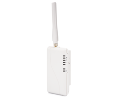
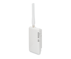
The Telguard TG-1 Express is a cellular communicator for old hardwired panels that use POTS (plain old telephone service) connectivity. It is available in AT&T LTE and Verizon LTE variants. The TG-1 will take over the panel's phone dialer so that it can communicate across a cellular network. The panel will still think it is dialing out like normal, but really the phone line signal is being converted into a cellular signal. The advantage to this is that cellular connectivity is much more reliable than POTS connectivity. You can even using the TG-1 Express to set up your system with the Telguard HomeControl Flex platform for remote security and automation control using a mobile app or web browser.
Normally, the Telguard TG-1 Express is used when replacing the POTS connection on an older panel. The typical installation for the TG-1 Express involves using the panel's existing RJ31X cable. This is usually plugged into an RJ31X jack. In that type of setup, the RJ45 connection provides both power and Tip & Ring for the TG-1 Express. For a more typical installation, we strongly recommend checking out this helpful FAQ, as that setup will provide all the necessary connectivity, without needing to use the TG-1 Express terminal block.
However, some DIY users may find that the unused leads from the RJ31X cable were previously cut, as they don't really serve much purpose in a typical POTS configuration. In that case, then you can use the existing RJ31X cable to connect the TG-1Express to the panel's Tip & Ring terminals, and then create a new 2-wire connection between the panel and the TG-1 Express for power. That is what we will cover in this FAQ. Please note that you will not need the RJ31X jack for the setup, only the RJ31X cable.

Remember that the Telguard TG-1 Express will draw up to 115mA of current when transmitting signals. Make sure your panel is able to handle this additional current. If not, consider adding an external power supply. If you do use an external power supply, then the power connections from the TG-1 Express will connect at the auxiliary terminals on the power supply. For this FAQ, we will assume that no external power supply is being used.
Complete the following steps to set up a Telguard TG-1 Express if the orange and blue leads on your existing RJ31X cable have been cut or removed:
1. Power down the panel. Always make sure to power down your panel before making hardware changes. Disconnect the backup battery, and unplug the transformer. You may need a screwdriver to unplug the transformer, as it may be screwed into the wall outlet. Ensure that your panel is fully powered down before continuing.
2. Open the TG-1 Express. As part of this process, you will want to have the TG-1 Express opened. Press in the two (2) tabs on the front of the TG-1 Express using a flat head screwdriver. You should then be able to easily separate the front cover from the TG-1 Express.

3. Configure Tip & Ring. You will use an RJ31X connection between the Telguard TG-1 Express and the panel for Tip & Ring. First, locate the existing RJ31X cable for your panel's old POTS connection. The RJ31X cable is most likely connected to an RJ31X jack. Remove the cable from the jack. You will not need the RJ31X jack for the process, so you can remove it. The picture below shows an RJ31X jack and the connected end of the RJ31X cable.

Take the end of the RJ31X cable that was connected to the RJ31X jack, also known as the modular end, and connect it to the RJ45 port on the TG-1 Express. Make sure to run the wire through the opening at the bottom of the TG-1 so that you can properly close the communicator later. The picture below shows the TG-1 Express RJ45 port.

If the TG-1 Express is replacing an existing POTS phone connection, the other end of the RJ31X cable will already be connected to the Tip & Ring terminals of the alarm panel. Otherwise, next you will connect the flying leads from the RJ31X cable to the panel for the Tip & Ring connections. The Green lead should go to the designated Tip terminal on the panel. The Red lead should go to the designated Ring terminal on the panel. Remember to run the wire through the back of the panel's enclosure, or one of the designated side knockouts so that you can properly close the lid.
4. Connect for power. There will be a 2-wire connection between the TG-1 Express and the panel for power. We recommend using 22-gauge, 2-conductor wiring for this purpose. However, nearly any wire you have on-hand should work fine. Remember to run the wire through the respective back plates of both the TG-1 and the panel.
The terminal block for the TG-1 Express may not be attached to the unit when it first comes out of the box. You can see it completely removed in the previous image. It will connect by simply sliding over the pins that are coming off of the main PCB. When the terminal block has been put into place it covers up the labels for the terminals. In the picture below, we have removed and tilted back the terminal block to show the labels. You will be working with the two (2) terminals on the far right. These are the GND terminal for negative (-) power, and the DC terminal for positive (+) power.

You can also see the terminals labeled on the quick install guide for the TG-1 Express.

And this picture shows the terminal block normally. This is the position it should be in when you connect the power wires. Note how it covers up the labels.

We recommend following proper wire color codes to avoid confusion. Using a 2-conductor wire, you will connect the black wire at the GND terminal for negative (-) power, and the red wire at the DC terminal for positive (+) power. Make sure to run the wire through the rear opening on the TG-1 Express so that you can close the unit later.
You will then complete the power connections at the panel side. Most hardwired alarm panels will have auxiliary power terminals for this purpose. The labels for these terminals can vary between different panels, so refer to the instruction manual for your panel for more information. Usually, the panel's auxiliary power terminals will also be where keypads and motion detectors connect for power. Connect the black wire at the AUX Negative (-) terminal, and connect the red wire at the AUX Positive (+) terminal. Remember to run the wires through the back plate prior to connecting.
Note: If you are using an external power supply, then the power connections will be made between the TG-1 Express and the DC Negative (-) and DC Positive (+) terminals on the power supply. When using a separate power supply, a common negative between the panel and the power supply is usually required. This just entails connecting a wire from DC Negative (-) on the separate power supply to Aux Negative (-) on the alarm panel.
5. Connect the antenna. Secure the antenna to the Telguard TG-1 Express. You should be able to spin it into place. The picture below shows the connected antenna with the module still opened.

6. Power on the panel. Connect the backup battery for the panel. Then plug its transformer back into the wall outlet. Reapply the screw for the transformer, if necessary. You will know that the Telguard TG-1 Express is receiving power because LED light 8 on the module will light up.
7. Check signal strength. Before mounting the TG-1 Express, you want to check its signal strength. This can be done before the module is activated for monitoring service. Make sure the antenna for the unit is properly secured before checking signal strength. To check signal strength, press the RSSI (Received Signal Strength Indicator) button on the right-hand side of the TG-1 Express when facing the module. Pressing the button will switch the LED function of the unit to show signal strength.

The table below shows the meaning of the various LED lights for checking signal after pressing the RSSI button.
|
RSSI Value |
Illuminated LEDs |
Signal Strength |
|---|---|---|
|
NSC |
LED 5 = Flash, LED 4 - 2 = OFF |
No Signal |
|
1 |
LED 5 = On, LED 4 - 2 = Off |
Poor |
|
1 1/2 |
LED5 = On, LED 4 = Flash, LED 3 - 2 = Off |
|
|
2 |
LED 5 - 4 = On, LED 3 = Flash, LED 2 = Off |
Fair (Min. Required) |
|
2 1/2 |
LED 5 - 4 = On, LED 3 = Flash, LED 2 = Off |
Good |
|
3 |
LED 5 - 3 = On, LED 2 = Off |
|
|
3 1/2 |
LED 5 - 3 = On, LED 2 = Flash |
Excellent |
|
4 |
LED 5 - 2 = On |
To achieve the best possible signal, it is advised that you have the antenna positioned as high as possible. It should be away from sources of RF interference, including any large metal objects. It should be mounted in a vertical position, not horizontal, and it should not be touching any other object.
8. Mount the unit. It is now time to mount the TG-1 Express in the location that provides the best possible signal strength. Telguard recommends connecting an Earth Ground to the PCB screw terminal on the bottom-left of the module. An example of a good Earth Ground is a cold water pipe.

Start by installing mounting screws. These are not included with the TG-1 Express, so you will need to supply your own. There are keyhole style mounting holes on the back plate. These mounting holes are 2.5 inches apart at their center locations. Install screws, and use drywall anchors if needed. Then slide the back plate onto the screws. Remember to feed all the wires through the access hole. We recommend making a small hole in the drywall behind the wiring access area to feed wiring through the hole. Your wired alarm panel likely has a similar wire feeding hole.

9. Apply the front cover. When applying the TG-1 Express cover, position the upper portion first. Then lock the two (2) lower tabs into place. The lower tabs should click into place, and the front cover will be secured.
10. Activate for monitoring. Contact your alarm monitoring company to activate the TG-1 Express. If you are being monitored by Alarm Grid, then you must sign-up for a monitoring plan. An activator will contact you during the activation appointment you selected. Remember that you must choose a monitoring plan that includes cellular connectivity. Follow these tips to ensure that your activation goes as smoothly as possible.
Did you find this answer useful?
We offer alarm monitoring as low as $10 / month
Click Here to Learn MoreRelated Products
Related Videos

Related Categories
- Answered