How Do I Connect a TG-1 Express to my Older Legacy Panel?
The Telguard TG-1 Express should be mounted as near the panel as possible, while still being able to receive a good cell signal. It will connect to the panel's phone terminals and to auxiliary power through the RJ45 connector on the board. Use the existing RJ31X cable for this purpose.
The most common reason customers move to a TG-1 Express is when phone service has been discontinued for the location. The device is also recommended for use when the phone service uses Voice over IP, which is not reliable for conveying signals on an alarm panel.
Complete the following steps to connect a TG-1 Express to an older legacy panel:
1. Determine the appropriate equipment. Find the existing RJ31X Jack. This was used to connect the alarm panel to the existing home phone wiring. Most alarm panels that previously utilized POTS (Plain Old Telephone Service) were connected to the phone wiring using an RJ31X Jack. This was a small, beige square with a modular receptacle. It looks much like a phone jack. This device also included a thick, gray wire with a modular plug at one end, and flying leads with spade lugs at the other end. These spade lugs connected to the alarm panel's telephone terminals, while the modular plug connected to the RJ31X Jack. If you have one of these jacks, you can use the cable from it to successfully connect the TG-1 Express to the panel. If you can't find one of these jacks nearby, we would recommend purchasing this one.
Below is a picture of a common RJ31X Jack:

2. Connect the TG-1 Express. You will not be able to verify adequate signal strength to the TG-1 Express until you power it up. For this reason, make sure there is enough wire between the communicator and the panel to allow you to move the TG-1 Express later. Once you have applied power, you will want to move the TG-1 Express around to find the best mounting location. You will also need to re-run the wires out of site after you find a suitable location.
First, power the panel completely down. Disconnect the wires going from the alarm panel to the back-up battery. Find the transformer for the security system, and unplug it. The transformer may be screwed into the outlet, so make sure to have a screw driver on hand. If you cannot find the transformer, you may be able to shut off the breaker for the outlet instead. Once you have verified that the panel has powered down, indicated by the keypad display going blank, you can make the wiring connections for the TG-1 Express.
Using either the RJ31X cable that was already installed with your alarm panel, or the one that was purchased, make the following connections:
Connect the Green flying lead to the terminal marked Tip on your alarm panel.
Connect the Red flying lead to the terminal marked Ring on your alarm panel.
Connect the Orange flying lead to the terminal marked Auxiliary Negative.
Connect the Blue flying lead to the terminal marked Auxiliary Positive.
When being powered by 12-volts DC, the TG-1 Express draws 64 mA of current in standby, and briefly draws up to 115 mA when transmitting. Make sure that your alarm panel has enough current available to handle this added power load. Verify that all wiring connections are secure in their terminals. Finally, plug the modular end of the Gray RJ31X cable into the RJ45 Jack located on the TG-1 Express.

3. Power the panel. Connect the panel's backup battery. Plug in the AC transformer, and re-apply the screw if applicable. If the breaker was turned off, turn it back on. Verify that LED 8 illuminates on the TG-1 Express, indicating that power is present.
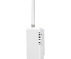
4. Verify signal strength. Once the TG-1 Express is powered up, verify adequate signal strength. Make sure that the provided antenna is mounted and securely attached to the unit. The TG-1 Express features eight LED's, which provide a variety of data. When the RSSI (Received Signal Strength Indicator) button is pressed and then released on the right side of the unit, it switches the LED function. It will then display signal strength. This will work, even if the device is not yet activated.
The chart below provides a key to deciphering the RSSI LED's:

|
RSSI Value |
Illuminated LEDs |
Signal Strength |
|---|---|---|
|
NSC |
LED 5 = Flash, LED 4 - 2 = OFF |
No Signal |
|
1 |
LED 5 = On, LED 4 - 2 = Off |
Poor |
|
1 1/2 |
LED5 = On, LED 4 = Flash, LED 3 - 2 = Off |
|
|
2 |
LED 5 - 4 = On, LED 3 = Flash, LED 2 = Off |
Fair (Min. Strength Required) |
|
2 1/2 |
LED 5 - 4 = On, LED 3 = Flash, LED 2 = Off |
Good |
|
3 |
LED 5 - 3 = On, LED 2 = Off |
|
|
3 1/2 |
LED 5 - 3 = On, LED 2 = Flash |
Excellent |
|
4 |
LED 5 - 2 = On |
Tips for achieving the best possible signal strength:
The higher the antenna, the better.
Try to keep the antenna away from sources of RF interference, including pumps, compressors, ovens or any other large metal objects.
Mount the antenna vertically - never horizontally.
Do not allow the antenna to touch any other object.
5. Mount the TG-1 Express. Once you have found a mounting location that provides the best possible signal strength, permanently mount the TG-1 Express. It is recommended to connect an Earth Ground, such as a cold water pipe, to the PCB screw terminal on the lower left of the unit.

Install mounting screws, which are not supplied. The "keyhole" style mounting holes on the back mounting plate are 2.5 inches apart at their center locations. Install screws, using drywall anchors if necessary, and then slide the back mounting plate onto the screws. Make sure to feed all wires through the wiring access hole.
If the TG-1 Express is being mounted to a finished wall, it is recommended that a small hole be made in the drywall directly behind the wiring access area. The wiring can then be fed through that hole, through the wall, and into the alarm panel's metal enclosure. The alarm panel will also have wiring access holes with sections of the metal enclosure knocked out for this purpose. This will require that Step 2 and Step 3 be performed again. The four wires being fed from the alarm panel to the RJ45 connector on the TG-1 Express should be removed, fished through the wall, and re-connected permanently.

6. Mount the cover and finish. Place the cover on the TG-1 Express by lining the tabs up at the top, then snapping the bottom into place. Make sure no wires are pinched in the process. Work with your alarm dealer through the remainder of the registration process.
NOTE: The TG-1 Express is capable of providing limited Remote Services through their HomeControl Flex feature. Use of this feature requires additional wiring and configuration, details of which will be determined by the alarm panel being used. Not all panels will support this feature. Alarm Grid recommends upgrading to a panel that supports either Total Connect 2.0, or Alarm.com if you want to take advantage of this type of service.
Did you find this answer useful?
We offer alarm monitoring as low as $10 / month
Click Here to Learn MoreRelated Products
Related Videos

Related Categories
- Home Security Systems
- Business Security Systems
- Apartment Security Systems
- Monitored Home Security Systems
- Small Business Security Systems
- Cellular Alarm Communicators
- DIY Wired Security Systems
- Answered
- Answered By
- Julia Ross