Adding a Second Push-button Keypad to a Vista-20P
Related Products


Related Categories
Description
In this video, Joe explains how to add a second push-button keypad to a Honeywell VISTA Panel. A push-button keypad can refer to an Alphanumeric Keypad or a Fixed English Keypad. Either way, you will need to wire the keypad to the system, and you will need to properly address the newly added keypad.
Adding a second keypad will offer you flexibility when controlling your alarm system. This will allow you to control your system from two on-site locations. For example, you might have one keypad by your front door and another by your back door so that you can conveniently access it from either location. A second keypad can also be a good backup, in case there is ever something wrong with the primary keypad. Fortunately, adding a second keypad is a very easy process.
When adding a second keypad, you will first want to power down the panel. This is done by disconnecting the backup battery and unplugging the transformer. Then wire the new keypad to the ECP bus. A keypad will use a 4-wire connection and go to the same terminals as the existing keypad. These are terminals 4 thru 7 on the panel. An 18-gauge, 4-conductor cable is recommended to complete the wiring process. Finally, you will address the keypad. You can use addresses 16 thru 23 on a VISTA P-Series Panel. Address 16 is usually for the primary keypad, so a secondary keypad will normally use an address of 17 thru 23. Remember to enable to address if necessary.
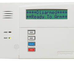
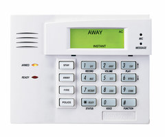
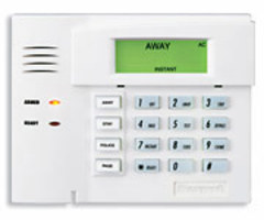
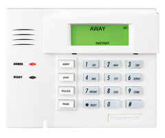
You should then make sure to test the keypad to ensure that it is working correctly. A good way to do this is by arming and disarming with the new keypad. If you can arm and disarm successfully, then the new keypad is working properly. Remember that you can add up to eight (8) keypads on a VISTA P-Series Panel. We always recommend having at least one Alphanumeric Keypad so that you can perform deep-level programming. Some good Alphanumeric Keypads are the Honeywell 6160 and the Honeywell 6160RF.
http://alrm.gd/get-monitored
Transcript
Hi, [INAUDIBLE]. Joe here, from AlarmGrid. And today we're going to show you how to add a second push-button keypad to a VISTA-21iP. Now this works exactly the same on your VISTA-20P so, for either panel, this process will work. Today we have our 21iP set up and we already have a 6150 connected to the system as a working keypad. Now we're going to add in the 6160 as the secondary keypad on this system. But first, we're going to have to power the system down 100% and connect the 6160 via wire to the system's terminals. So I'm going to undo the main power for the system and then unplug the backup battery. Now I have my 6160 wire right here and I have it set up to go into the terminals. It goes-- terminal 4 is negative power, that's black. Terminal 5 is positive power for 12 volts DC, that's the red. Terminal 6 is for my data and terminal 7 is for my data. And if we look at our wiring diagram, it'll say terminal 6 is for green, terminal 7 is for yellow. It's just the data going in and out and it's a way that they have it set up, so that it does work when you do connect it to the system. But I'm going to loosen up the terminals on the system. These are the existing things that are connected and then I'm going to simply slide my wires under each respective terminal. And I've tried to do it in such a way where it makes my life a little easier when I slip the wires in, as I can, kind of, all push them in around the same time. I'll go ahead and tie them all down. Just to make sure my connection is nice and secure, a little tug shows that it's not going anywhere. So now I'm going to replug in the backup battery and replug in the panel. Now before I plug in the panel, I just want to go over a couple of important things. One, when you're adding a second keypad to the system, you have to do this next process within 60 seconds of powering the system up. So after we power it up, we're going to go ahead and address the keypad and get it working. On the VISTA systems, the 20 and the 21iP, the keypad addresses go from 16 and 24 for the push-button keypads, so you can have 8 of these connected to the system. We do have the secondary address set up for our second keypad, which is address number 17, so we'll be able to program this keypad to that address and it's going to work out right. After we do that, though, we're going to show you how to enable the address, in case the system doesn't have the address enabled. And also, if your system is a VISTA 20P with revision 10.23 or higher, this keypad address is already enabled. So you'll only have to do this next keypad address enabling process if your system is a 20P below that revision level, or if it's a lower model system. But now that we have our system wired up, let's go ahead and plug it back in and then set our second keypad to address number 17. So I have my backup battery plugged in. I'm going to plug in my main power and the system is powering up. So now, I believe, right now, we can actually address this keypad. So I'm going to go ahead and press 1 and 3 and we do have the address programming. I'm going to enter 0-0 to clear out the initial entry and then I'm going to enter 1-7. So it's going to be address 17. Star to confirm. This has an RF module in it. We're not going to go into this right now, but that's what these menus have to do with. I'll just confirm that the receiver is on. The receiver address is 0-0, that's correct. I'll confirm. We don't want high security and we don't want to disable high security devices. The panel's still going through its boot process. That's what we see on the screen right now. And there we go. So we're on our main menu. The keypad is showing disarmed, ready to arm. And it looks like everything is working just fine. If we go to arm the system, with our default code 1-2-3-4 and then 2, we should be able to arm the system from the keypad. And it is working, so let me just disarm the system. Great. So our keypad is working. Now let's show you how to enable this keypad address, if it wasn't already enabled on your system. So each of these keypad addresses are set to a different programming field in the system. The keypad address that we want to enable-- it already is, but assuming that it wasn't-- is 17. This would be programming field 190. The keypad addresses go up from there and, if you check your programming guide, you'll see all the instructions for doing this, if you want to use that as a reference. Once we get into that programming on the system, we'll have to tell the system which partition the keypad is going to live in. And then we also have to tell it if we want to nullify or suppress any of the noises that come from the keypad. We want it to be in partition 1, and we also want all the noises to be enabled, which is likely going to be how you program most of your keypads. If you do want to alter any of that or try some of the other options out, check out the fact that's associated with this video, as there's going to be information there with all the different options available to you for this process. First I need to get into keypad programming. Let's do 4-1-1-2-8-0-0. So now I need to select keypad address number 17. To do that I'm going to do star-1-9-0. And as you see, we have keypad address 17. From here, based on the next two digits that we enter, we're going to tell it which partition we want it to live in and if we want all of the noises coming from the keypad to be enabled. So to do that, I do want this to work and partition 1, so the first digit I'm going to hit 1. And then I do want all of the sounds to be enabled. So to do that I'm going to hit 0. The three beeps that we just heard, that confirms that our programming edits were successful. And as you see here, it's gone to keypad address number 18. So this will walk you through all the keypad addresses, if you do actually want to enable all of them or edit them. If you don't though, after you do your edit-- just hit star-9-9, back out of programming, and we're back to the main menu. If you do have any questions about adding a secondary push-button keypad to your VISTA system, or alarm questions in general, feel free to give us a call at 8-8-8-8-1-8-7-7-2-8, send us an email to support@alarmgrid.com, or head to our website at www.alarmgrid.com. You did like the video? Feel free to subscribe. And if you want to be notified when we post future videos, hit the notification button below, and we'll send you an update when we do so. Thanks for watching and have a great day.
- Uploaded