How Do I Install The PRODCM in an LTEM-PA or LTEM-PV?
To install the PRODCM remove the communicator cover. Disconnect the DC Power Adapter, then disconnect the red battery lead. The LEDS should go out, indicating that the unit is powered down. Install the PRODCM in the upper right side of the mainboard, making sure it is completely seated.
The Resideo PRODCM is used when an alarm panel doesn't support the LTEM-PA or LTEM-PV in ECP Mode. ECP Mode allows a communicator to connect to the keypad bus of a VISTA alarm panel, and report all signals directly through it. There are certain panels from DSC that can use the LTEM-P Series device for reporting and access to Total Connect 2.0 without requiring the PRODCM to be installed. Regardless of how the communicator connects to the alarm panel, information is always transmitted in Contact ID format. Contact is a high-speed, DTMF (touch-tone vs. rotary) format that transmits information very quickly. In order to use the PRODCM with a panel, the panel must support the Contact ID format, and it must be set to report using Contact ID.
Adding the PRODCM and connecting the panel's Tip and Ring telephone terminals to the terminals on the PRODCM allows the communicator to emulate a phone connection to the panel. When the panel is ready to send a signal, the communicator provides off-hook voltage to the panel so that it thinks a phone connection exists. Once the panel dials, it doesn't matter what number it dials, but there must be something programmed for the phone number, the PRODCM then provides the Contact ID handshake. This tells the panel to transmit its signal or signals. Once the signal has been transmitted successfully, the PRODCM then provides the panel with an acknowledgement, known as a kiss-off. When the panel hears the kiss-off, it knows that it has transmitted a successful signal, or signals and it hangs up without trying to send again. In the meantime, the PRODCM is capturing the information being transmitted through the Tip and Ring terminals from the panel, and is then sending that information through IP or Cellular communication to AlarmNet, and then on to the Central Station when applicable.
To install the Resideo PRODCM into a LTEM-PA or LTEM-PV, perform the following steps:
- Remove the cover. If the communicator has the cover on, remove it by unscrewing the set screw on the bottom edge of the unit. Once the screw has been removed, put it in a safe place then press in on the bottom locking tabs and pull the bottom of the cover forward. Once the bottom edge has cleared the locking tabs, pull the cover straight up and then forward to remove it.
- Power down. If the communicator has been powered on, power it down by unplugging the DC Power Adapter, then removing the red battery lead. All of the communicators LEDS should turn off. This indicates that the unit has been powered down.
-
Mount the PRODCM. Slide the PRODCM connector onto the LTEM-P Series communicator's upper right edge connector. Once it has been securely attached press it so that the top edge of the PRODCM is under the Retaining Clip Tab.

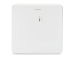
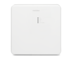
PRODCM Front:
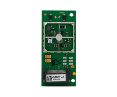
PRODCM Back:
PRODCM Connector:
-
Connect Tip and Ring. Using either two (2) new pieces of wire, or existing wires, connect the control panel's Tip and Ring terminals to the two available terminals on the PRODCM. Be sure to connect to the panel's EXTERNAL Tip and Ring terminals, not those for the house phone side. The terminals at the PRODCM are not polarity sensitive, so it does not matter which panel terminal connects to which PRODCM terminal.
The external Tip and Ring wires at the panel are usually Green and Red respectively. The wires for the house phones are usually marked as Gray and Brown in color. You will not be connecting anything from the panel's house side terminals to the PRODCM. In the image shown below of a panel's terminals and an RJ31X Jack, the external Tip and Ring terminals are marked as INCOMING, and the house phone side is marked HANDSET.
It is likely, if the panel has been monitored via a POTS line in the past that it has an RJ31X Jack installed. An RJ31X Jack allows the phone line to be quickly disconnected from the alarm panel in the event of an issue. This removes the panel from the phone line while keeping the house phones connected. If this wiring is already in place, you can use the RJ31X jack to connect to the LTEM-PA or LTEM-PV. Since there is no actual phone line in use, no connection to the house side phone terminals at the panel is required.
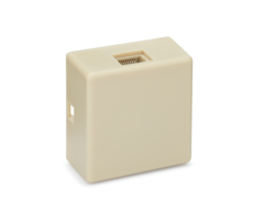
Below is an example of an RJ31X Jack. When in use, it will have a modular connector plugged into the port, as you can see in the second image. This connector will have eight (8) wires coming off of it. Four (4) of these wires will be connected to the panel's phone terminals:

Below is an image of the PRODCM installed in the LTEM-PA or LTEM-PV. You can see the two (2) terminals that will be used for the connection to the panel's phone terminals. In addition, you can see a panel with phone terminals and an RJ31X Jack. In this image, Tip and Ring are marked in Red and Green with the word INCOMING above them. If there is an existing RJ Jack, you can either take the wires that are connected to its terminals 4 and 5 and connect those to the PRODCM terminals, while leaving everything from the RJ jack to the panel alone. Or, alternatively you can remove the existing wires from the RJ jack and run new ones from terminals 4 and 5 to the PRODCM. If there is no RJ31X Jack at the panel, simply connect the PRODCM terminals to the terminals marked Incoming Tip and Ring on the panel. Again, Tip and Ring are usually indicated with a Green and a Red wire respectively.

-
Finish up. Once all the wiring has been completed for the PRODCM, you'll need to power the communicator back up and replace the cover. There is a knockout in the plastic directly to the right of where the PRODCM is installed. Using needle nose pliers, or a similar tool, break this section out so that the cover will fit flush back on the communicator.
Plug the DC Power Adapter in, then reconnect the Red lead for the battery. The LTEM-PA or LTEM-PV will begin the power-up sequence. Settle the top of the cover onto the top of the communicator, allowing the retaining tabs at the top to line up. Swing the cover into place and snap the bottom into the locking tabs there. Reapply the set screw to the bottom of the communicator.


Notes regarding the dialer capture module:
- The dialer capture module is good only for communication from the panel to a central station. It can't be used with Total Connect 2.0 (except for certain Interlogix NX panels, as mentioned in this post), or with the Compass or any other downloading software.
- If the communicator loses power, the module can't generate a fault trigger to the alarm panel. In this case, if the panel still has power, and is trying to communicate, it will eventually reach the end of its retry attempts and at that point will display a comm failure at the panel.
- The dialer capture module can't sense a fault on the Tip and Ring terminals. But, if the module is attempting to forward alarms and it can't, then it will trigger a fault and disable the emulated phone line (which may cause a Telco Fault at the panel, depending on various factors). The emulated phone line will be restored once (IP or Cellular) communication has been re-established.
- In a similar fashion to the note above, if the Dialer Capture module senses a fault, it will send a Trigger signal to the panel (if connected) and will also drop phone line voltage, not providing a dial tone to the panel if it attempts to communicate a signal. If the panel is attempting to send a signal, it will make the programmed or pre-set retry attempts. Until the panel has finished retrying to send the signal it will not be able to sense a "Telco Fault" condition. To minimize the wait time for a Telco Fault in this circumstance, for those panels that allow you to set a Telco Fault detection time, it should be set to the minimum time allowed.
- Some panels may indicate Telco Fault conditions in error based on grounding or lack thereof. If the panel used has this issue, then disable Telco Fault monitoring at the panel.
- If the PRODCM receives a communication path (IP or Cellular) failure from the communicator, the module will drop voltage to its Tip and Ring terminals, disabling the "phone" line. If Telco Fault monitoring is enabled, then the panel should display this condition at the keypad. When the PRODCM receives a restore of the communication path issue, it will re-enable the "phone" connection for the panel, and any Telco Fault should restore. Any other faults are signaled to the panel via the Fault Trigger being wired to a zone on the panel.
Notes on panel programming required when using the PRODCM.
- The panel must be enabled for DTMF Touch Tone dialing. Pulse dialing must disabled.
- If the panel supports PABX dialing (like dialing a 9 before dialing the actual phone number) then this feature must be disabled.
- Phone numbers and account numbers must be programmed into the panel. What these numbers are is not important, but something must be programmed for each, and the account number should have the correct number of digits, which is four (4). In order to give the system the maximum number of tries to successfully send a signal, it is recommended that both primary and secondary account numbers and phone numbers are configured.
- Report format must be set to Contact ID.
- If programmable, be sure that the maximum number of communication attempts is enabled.
- Every reporting option that is desired should be properly enabled for reporting, such as zone report codes, restore report codes, non-alarm report codes for system conditions such as AC Loss and Low Battery, etc.
Did you find this answer useful?
We offer alarm monitoring as low as $10 / month
Click Here to Learn MoreRelated Products
Related Categories
- Dual-Path Alarm Communicators
- LTE Cellular Communicators
- LTE Cellular Communicators
- Verizon LTE Cellular Communicators
- Alarm Monitoring Communicators
- Cellular Alarm Communicators
- Cellular Alarm Communicators
- Alarm Monitoring Communicators
- Internet Alarm Communicators
- AT&T LTE Cellular Communicators
- Universal Alarm Communicators
- Answered
- Answered By
- Julia Ross