How Do I Add a 6150RF Keypad to My VISTA 20P?
You can add a 6150RF Keypad to your VISTA 20P by wiring it to the panel and addressing it accordingly. The keypad will use panel terminals 4 thru 7 for wiring. It will use a single address of 16 thru 23. The RF receiver function should work automatically, with no additional programming.

Since the Honeywell 6150RF is a Fixed English keypad, it should not be used for deep-level programming. As a result, it should only be used as a secondary system keypad. If you need a primary keypad for deep-level programming, then the Honeywell 6160RF is better-suited for the task. The Honeywell 6160RF is an alphanumeric keypad that also includes a built-in wireless transceiver for supporting wireless 345 MHz sensors from the Honeywell 5800 Series.
Complete the following steps to add a 6150RF Keypad to your VISTA 20P:
1. Power down the panel. Always power down the panel before attempting to add a new hardwired keypad. Failing to do this could result in damage to the system. Disconnect the backup battery and unplug the AC transformer to power down the system.
2. Wire Keypad to panel. The 6150RF will connect with the VISTA 20P using a four-wire connection. Two wires are used for power, and the other two are used for data. Panel terminals 4 thru 7 are used. We recommend using an 18-gauge, 4-conductor wire to complete the wiring. However, it's okay if a slightly higher or lower gauge is used.
The black wire for negative (-) power goes to terminal 4. The red wire for positive (+) power goes to terminal 5. The green wire for data in goes to terminal 6. The yellow wire for data out goes to terminal 7. Make sure that all connections are nice and secure before continuing.

3. Connect wires to keypad. Next, you will wire the other end of the 4-conductor wire to the 6150RF Keypad. Remove the back cover for the keypad, and run the wire through the back plate before wiring. Failing to do this will prevent you from closing the back cover later.
Locate the terminals labeled G, -, + and Y. The green wire goes to G. The black wire goes to -. The red wire goes to +. The yellow wire goes to Y. Make sure all connections are nice and secure. You can close the keypad when finished.


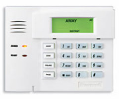
4. Address and test. Power the system back on by reconnecting the plug-in transformer. You can worry about reconnecting the backup battery later. You need to work quickly once the system is powered back on. Within 60 seconds of restoring power, press and hold the [1] and [3] keys on the 6150RF Keypad. This will have the keypad enter its programming mode. This will be indicated with a 00 and -- flashing alternately on the screen.
Press 1 to enter the keypad address portion of programming. The display will show cA - 31 (the default keypad address). cA stands for Console Address. Enter [00] to clear the current address. Then enter the desired 2-digit address, and press [*] to save your selection. This will return you to the 00 -- alternating flash. The VISTA 20P System will support addresses 16 thru 23. Address 16 is usually used with the primary system keypad. Since the 6150RF is a Fixed English keypad, it probably isn't going to be your primary keypad. Most users will already have an Alphanumeric keypad assigned to Address 16 before they attempt to program a 6150RF.
As a result, you will most likely be assigning an Address of 17 thru 23 for your 6150RF. Unlike Address 16, these Addresses are not enabled by default (on rev 9 and older panels, in revision 10, all keypad addresses are enabled by default). If your panel is a version 9 or older, you will need to go into programming and enable the desired Address. This is accomplished using one of the programming fields from [*190] thru [*196]. More information is available in the VISTA 15P, 20P Programming Guide. Enabling the new keypad address should be done using the primary Alphanumeric programming keypad prior to Step 1.
After addressing,be sure to reconnect the panel's backup battery. The system probably already has a low battery condition displayed, but it should clear on its own soon after you reconnect the battery. If it doesn't clear right away, it should clear within 24 hours, and will probably clear within four hours. Test the keypad to make sure that it works properly. Make sure you can Arm Stay by entering [Master Code] + [3] and disarm by entering [Master Code] + [1]. Since the VISTA 20P is a VISTA P-Series Panel, the receiver address for the 6150RF keypad should already be enabled. This is assuming that the default configuration for the setting in the 6150RF has not been changed. By default, the 6150RF receiver is set to address 00, which is the correct address for use on the VISTA-20P.
Did you find this answer useful?
We offer alarm monitoring as low as $10 / month
Click Here to Learn MoreRelated Products

- Answered
- Answered By
- Julia Ross