How Do I Install a Honeywell LTEM-XA or LTEM-XV On a VISTA-128BPT or VISTA-250BPT?
You can install a Honeywell LTEM-XA or LTEM-XV on a VISTA-128BPT or VISTA-250BPT by mounting the communicator and completing its needed connections with the alarm panel. The communicator uses a 4-wire connection with the panel. You must then activate the communicator for monitoring service.

The Honeywell LTEM-XA and Honeywell LTEM-XV will work with any Honeywell VISTA System that supports the communicator in ECP mode. Both are cellular communicators that connect with highly advanced LTE Cat 1 M1 Networks. The LTEM-XA uses the AT&T Network, while LTEM-XV uses the Verizon Network. These new communicators replace the older Honeywell LTE-XA and Honeywell LTE-XV, respectively. They offer superior security and signal penetration when compared with their predecessors. All setup from the LTE-XA or LTE-XV remains exactly the same for these new modules. Honeywell VISTA Systems use these modules to communicate with the Resideo AlarmNet Servers. A cellular alarm monitoring plan, such as an Alarm Grid Gold or Platinum Plan will be required for activation. If your monitoring plan includes access to Total Connect 2.0, then you can use that service to control your system remotely.
For this FAQ, we will assume that the communicator is being mounted on the outside of the panel's metal enclosure. Mounting to a wall involves the same general process, but the connector wire must be adjusted accordingly. Complete the following steps to connect a Honeywell LTEM-XA or Honeywell LTEM-XV to a Honeywell VISTA-128BPT or a Honeywell VISTA-250BPT:
1. Test cellular signals. We recommend testing cell signals in the desired mounting location before permanently mounting the module. This can save you hassle later on, in case you need to relocate it. Testing signals involves powering on the unit and checking its signal LED light. You can power on the communicator using a 12V battery or power from the VISTA Alarm Panel.
In this FAQ, we will explain the process for powering on the communicator using panel power. To do this, begin by powering down the system entirely. This is done by disconnecting both the panel's backup battery and its plug-in transformer. Next, connect the included wiring harness to the ECP connection point on the communicator, then connect the red wire from the harness to Panel Terminal 6, and connect the black wire from the harness to Panel Terminal 7. There is no need to connect the yellow and green wires right now. Then restore panel power by plugging its transformer back into the outlet. Wait a few moments, and the LED lights on the communicator should illuminate. Check the signal LED, and make sure that it is solid green. This indicates that the signal is good. If you do not get a solid green signal LED, then you can try relocating the communicator or adding a cellular antenna or a cellular amplifier.

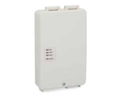
2. Mount the communicator. The communicator can be mounted to a wall using zip-it anchors or wall anchors, but we will be covering the process for mounting it to the outside of the panel. This is the easier and more popular option. The communicator will be mounted outside the panel's metal enclosure in the upper-right corner. You want to knock-out the round indented spot of the enclosure if you haven't already. The communicator's threaded cap will pass through this hole, and a metal washer will keep it fully secured.

The LTEM-XA or LTEM-XV has a threaded plastic hole-cap that passes through the hole in the enclosure's upper-right corner. Look at the image below to see how the threaded hole-cap secures into place on the communicator. Ensure that the hole-cap "snaps" into place upon securing.

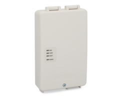
Once the hole cap is secured, take the communicator, and connect it with the panel's metal enclosure. The threaded portion of the hole-cap will pass through the hole in the panel's upper-right corner. Use the included metal washer to lock it into place. Review the diagram below for the connected communicator.

3. Complete the connections. Start by powering down your system again if it isn't already. Remember to disconnect the backup battery and unplug the transformer to power down completely. Then complete the wired connections. First, connect the included wiring harness for the communicator to the ECP port on the module. You may have done this already in Step 1, while you were checking the cellular signal strength. This connection can be seen in the above diagram. Take the harness wires, and run them down, through the hole-cap, and into the main panel area. Then connect the four (4) wires to the designated terminals. The connections are listed below.
- Red Wire to Terminal 6.
- Black Wire to Terminal 7.
- Green Wire to Terminal 8.
- Yellow Wire to Terminal 9.
 4. Activate for monitoring service. The last step is to activate the system for monitoring service. The VISTA System should be powered back on. Plug in the transformer before connecting the system's backup battery. The activation process is completed by your alarm monitoring company. You will need to provide the MAC and CRC codes for the communicator as part of the activation process. These codes are found on a white sticker inside the communicator.
Users who are signing up for Alarm Grid monitoring service for the first time will choose an activation appointment time slot when they sign-up. An activator will call you at the selected time. Make sure that all of the steps listed above are completed prior to your scheduled activation. We have activation slots available Monday thru Friday from 9am to 8pm ET. These slots are limited in quantity, so signing-up early is advised. If you cannot make your scheduled activation, or if your system is not ready, then please let us know beforehand as early as possible. You will be provided with a cancel/reschedule link via email when making your original appointment. This makes it easy to reschedule if the setup isn't complete before your appointment time. Just be sure to use the link prior to the beginning of the appointment. Once the appointment time rolls around, the link will no longer work.
If you are an existing Alarm Grid monitored customer upgrading to LTE, then you should email our support team at support@alarmgrid.com, letting us know the MAC and CRC of your new communicator. We will work with you to decide the best possible time to complete the upgrade. We have support hours available from 9am to 8pm ET Monday thru Friday. Let us know your desired time, and we will do our best to accommodate you.
Did you find this answer useful?
We offer alarm monitoring as low as $10 / month
Click Here to Learn MoreRelated Products


Related Categories
- Answered