How do I install the Honeywell iGSMV4G on my VISTA-15P?
The Honeywell IGSMV4G dual path internet and cellular communicator is a versatile, reliable unit for the Honeywell VISTA-15P alarm system. The speed of the primary internet path and the reliability that the back up 4G cellular path offers is excellent. Check out the IGSMV4G installation guidewhich is a great tool that walks you through the installation process step by step.
If this is a fresh installation follow these steps:
1. Test signal strength and determine location. (Install guide page 2-1)
Connect the unit's battery back up and AC power supply. Ideally, the communicator can sit beside the panel so boot it up in the spot where you'd like to mount it and check the RSSI (Received Signal Strength Indicator) LEDs for signal strength. You will need at least 3 LEDS (2 yellow, 1 green) for the minimum signal to function properly. This is a rough test so if you have 3 or more just move to the next step. Your monitoring provider will be able to do more accurate testing once registered.

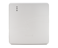
2. Mount the communicator. (Install guide page 2-2)
Mount the unit to the wall. This unit does not weigh very much so using zip-its or the included wall anchors will work well. Line up the back plate on the wall and trace the keyholes while making sure the unit is level. Then, drill starter holes for the anchors. Make sure to use a bit that is slightly larger than the small end of the dry-wall anchor. This way the anchor will slide in snugly. After you push in the anchors, screw in the screws leaving enough space for the back plate to be seated on the screws before they are tightened all the way. After seating the back plate on the screws you can fully tighten the screws so the device is snug to the wall.
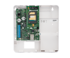
3A. Standard Install. Land power connections. (Install guide page 2-5.) Check out the VISTA15/20P quick install guide for a diagram of the alarm panel.

Power down completely by removing AC power and battery from the panel
Connect the transformer which was included with the IGSMV4G to terminals 1 and 2 on the communicator. Because this is AC power, polarity is not an issue. Connect one AC screw terminal from the transformer to terminal 1 on the communicator, and connect the other AC screw terminal to terminal 2 on the communicator. The transformer has a ground terminal in the middle, with the AC terminals being on either side. Do not connect the ground terminal to the communicator. After all connections have been made, including the communicator's backup battery plug in the transformer.
Connect the communicator to the alarm panel's keypad bus. Communicator terminal 3 goes to terminal 5 (AUX +) on the panel. Then connect communicator terminal 4 to terminal 4 (ECP - / Ground) on the panel. Connect communicator terminal 5 to terminal 7 on the alarm panel (White or Yellow wire). Connect communicator terminal 6 to terminal 6 on the alarm panel (Green wire). It may help to remember that these connections are always odd terminal number to odd number, and even terminal number to even number. The even terminal numbers being the same on both sides.

3B. Shared Transformer Install. Land power connections. (install guide page 2-9) Check out the VISTA15/20P quick install guide for a diagram of the panel.
Power down completely by removing AC power and battery from the panel.
Swap the alarm panel's existing transformer with the iGSMV4G's included transformer. Then wire communicator terminal 1 to panel terminal 1, and communicator terminal 2 to panel terminal 2. This will allow the alarm panel and the communicator to share the transformer, allowing the two devices to use only a single outlet. Do not plug the transformer back in until all wiring connections have been made.
4. Land data connections. (Install guide page 2-5)
Connect the communicator to the alarm panel's keypad bus. Communicator terminal 3 goes to terminal 5 (AUX +) on the panel. Connect communicator terminal 4 to terminal 4 (ECP - / Ground) on the panel. Connect communicator terminal 5 to panel terminal 7 (Yellow or White wire). Connect communicator terminal 6 to panel terminal 6 (Green wire). See the wiring image above for assistance.
5. Connect the included back up battery. (Install guide page 2-5)
Start off by placing the battery in the compartment in the lower right side of the back plate. Screw in the retainer clip to the backplate in order to secure the battery in place. Connect the red and black spade connectors to their respective tabs on the battery terminals. Then, plug the battery connection into the J1 battery port found on the communicator's board.
6. Reboot the alarm panel.
Connect the AC transformer to the wall outlet. Let the system fully power on. If faults appear, try doing a disarm to clear them. Keep in mind that you will get a tamper alert if the cover is off your communicator. If you are still testing you can leave the cover off. Once you've replaced the communicator's cover, a disarm at the keypad should clear the trouble message.
7. Program the IGSMV4G. (Install guide page 3-1)
Connect with a Honeywell dealer in order to activate and register the radio on the Alarmnet server. We offer no contract home alarm monitoring plans that include cellular communication. We can connect to your panel remotely using software that allows us to make any necessary programming changes for you. Simply sign up for the plan you would like and send us the MAC and MAC CRC address from the iGSMV4g. This can be found on a sticker inside the module and also on the box. Take a picture or jot down the numbers so you can email them to your alarm dealer.
If you have an existing GSMV that you are replacing with the IGSMV4G simply disconnect old unit and land the power and data connections on the new IGSMV4G. Do you have an older Honeywell VISTA-15P alarm panel and would like to install a dual path communicator and get Total Connect 2.0? No problem. Check out the IGSMV4G-TC2. This kit includes the IGSMV4G and an updated PROM chip that will bring your older panel up to the newest revision (Total Connect 2.0 requires revision 9.12 or higher) with the flick of a paper clip. Simply power down the system and remove the existing PROM chip and gently push the new PROM chip into place and voila! Power it back up and your system will be able to use Total Connect 2.0! Follow the steps above to install the communicator.
For further information on the IGSMV4G, please check out our FAQ page where you can also find the quick install guide.
Did you find this answer useful?
We offer alarm monitoring as low as $10 / month
Click Here to Learn MoreRelated Products


Related Categories
- Answered
- Answered By
- Frank Longo