How Do I Install the Resideo LTE-IA or LTE-IV On a VISTA-21iP?
You can install the Resideo LTE-IA or LTE-IV on a VISTA-21iP by testing signal strength, mounting the module, powering down the VISTA-21iP System, setting its IP/GSM jumper, connecting the communicator, connecting to the panel, powering the panel back on, and activating the communicator.
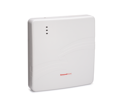
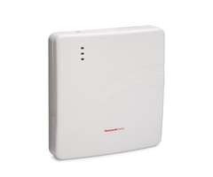
You may come across the LTE-IA or LTE-IV as the Honeywell Home LTE-IA and the Honeywell Home LTE-IV. Both are manufactured by Resideo, formerly Honeywell. For the most part, these are the same dual-path communicators for Honeywell VISTA Security Systems. The only difference between them is that the LTE-IA uses the AT&T LTE Network for cellular connectivity, while the LTE-IV connects through the Verizon LTE Network.
As for deciding between the two devices, you should go with whichever network provides more reliable service in the area where it will be used. Check coverage maps for AT&T and Verizon if you are unsure. Both units use a wired ethernet cable for IP communication. After the unit has been installed, it must then be activated for alarm monitoring service. You will want to get a monitoring plan that includes cellular connectivity so that you can use all the features that are available with these modules. An example of an appropriate monitoring plan is one of the Gold Plans from Alarm Grid. You can learn all about Alarm Grid monitoring plans in this post.
When using one of these communicators with a Honeywell VISTA-21iP System, there are a couple things to keep in mind. The first is that the system must be running at least Firmware Version 3.13 or higher to support Total Connect 2.0. This can be determined by checking the system's PROM Chip. For more information on checking a VISTA Panel firmware version and replacing a PROM Chip, please see this FAQ. If you determine that you need a replacement VISTA-21iP PROM Chip, you can obtain one here. Although you can technically use one of these communicators with a VISTA-21iP on a lower firmware version, this will forgo access to Total Connect 2.0. The module will then strictly be used for connectivity with a central monitoring station through AlarmNet360. In this configuration, you will lose out on the great features and convenience that comes with TC2. Therefore, connectivity with Total Connect 2.0 is strongly recommended.
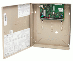
The other thing you must consider when using an LTE-IA or LTE-IV with a VISTA-21iP is that the system's internal IP communicator must be disabled. The Honeywell VISTA-21iP has a built-in IP communicator that can be used to connect with the AlarmNet servers across an internet connection. When you are adding an LTE-IA or an LTE-IV to the VISTA-21iP, you are upgrading the system to use dual-path (cellular and IP) connectivity. That way, if the internet goes down for some reason, the system will still be able to communicate using its cellular connection. But since you are adding an external communicator to the VISTA-21iP, its internal communicator must first be disabled. This is done by powering the panel completely down, and positioning the panel's internal IP/GSM jumper to the OFF position. We will cover more about this step later in this FAQ, but it is something to keep in mind when adding an external communicator to a Honeywell VISTA-21iP.
Complete the following steps to install a Honeywell LTE-IA or LTE-IV on a Honeywell VISTA-21iP System:
1. Test signal strength. When you are testing the signal strength for a cellular or dual-path communicator, you are determining whether or not the desired location for installing the unit will allow the module to achieve adequate cellular signal strength. This is important to do before mounting the communicator, as it will be more difficult to relocate the module after it has been hard-mounted. If you are having trouble finding a spot where a strong cellular signal is achieved, then you might consider adding a cellular antenna or a cellular amplifier to boost signal strength.
In order to check the signal strength for the LTE-IA or LTE-IV, you must provide power to the device. This is most easily accomplished by connecting the AC transformer or the backup battery for the device. The communicator can use its own transformer, or it can share a transformer with the VISTA-21iP Panel. More information on powering the communicator will be explained later in this FAQ, so refer to the later step if necessary.
But for now, once you provide basic power to the communicator, you will need to check the LED lights for the module. Seeing three (3) or more LED lights, with the first two (2) being yellow and the third (3rd) being green indicates that the communicator is receiving a strong enough cellular signal. While this is a very basic and rough way for determining cellular signal strength, it will get the job done for now. Your monitoring company will likely perform a more thorough and complete signal strength test once the unit has been activated and registered. You can cut power to the communicator when finished.

2. Mount the communicator. The next step is to mount the LTE-IA or LTE-IV unit to a wall. Mounting hardware for the device comes included. You can use the included wall anchors or zip-it anchors to complete the process. Note the mounting holes on the back of the unit. You want the back plate for the unit to be nice and level when it is lined up on the wall. The mounting hole locations should be marked before holes are drilled. Then slide the wall anchors tightly into place, and secure the unit with screws. You should leave space for the wall plate to sit on before fully tightening the screws. The back plate can be rested on the screws before they are tightened to secure it in place.
3. Power down the panel. Before continuing any further, you must make sure to power down the Honeywell VISTA-21iP Panel. This is done by disconnecting the backup battery and unplugging the transformer. The panel should not have any illuminated LED lights, and its connected accessories should go blank. If a connected keypad is receiving backup power from a secondary source, then you will get a message such as "Open CKT", "OC", or "ECP Error". These messages are normal, and they indicate that the main panel has indeed powered down. Failure to power down the panel before continuing could result in irreversible damage to the system and/or communicator.
4. Disable the internal communicator. Since you are installing an external communicator for a Honeywell VISTA-21iP System, the panel's internal IP communicator must be disabled. This is done by moving the panel jumper marked "Internal IP/GSM Jumper" from the top two pins to the bottom two pins. Doing this will cut power to the internal communicator so that the added external communicator will work properly. You can see the IP/GSM jumper in the following diagram.

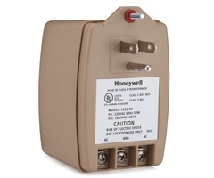
5. Wire the communicator. This step will involve both providing primary power to the communicator and connecting the unit with the panel. Both the LTE-IA and the LTE-IV can receive primary power from a Honeywell 1361-GT Transformer. This is a 16.5VAC, 40VA transformer. It can be used to power both the panel and the communicator, or it can just be used to power the communicator, depending on the type of setup you want to achieve. Since AC power is being used, you will not need to worry about polarity when connecting wires at the transformer.
If the transformer is being used to only power the communicator, and not the panel, then connect Terminals 1 and 2 on the LTE-IA or LTE-IV to the power terminals on the transformer that was provided with the communicator. Once those connections have been made, the communicator will still need to be connected with the panel's keypad bus for proper communication. The transformer should not be plugged in at this time. All wiring should be completed prior to initial power up.
The other option is to use the same Honeywell 1361-GT Transformer to power both the panel and the communicator. The VISTA-21iP comes with the same transformer as the communicator. Assuming the panel is using the transformer that came with it, you can continue to use it. You can keep the 1361-GT that came with the LTE-IA or LTE-IV as a backup. Once you have verified the transformer in use has the proper specifications, simply connect Terminals 1 and 2 from the VISTA-21iP to Terminals 1 and 2 on the LTE-IA or LTE-IV. This connection allows the communicator and the VISTA-21iP to share the power supplied from the transformer. You should not plug in the transformer at this time.
Regardless of whether or not the panel and the communicator are sharing a transformer, the following connections between the panel and the communicator will always be made:
- Connect Terminal 5 (AUX+) on the VISTA-21iP to Terminal 3 (ECP+) on the LTE-IA or LTE-IV.
- Connect Terminal 4 (GND) on the VISTA-21iP to Terminal 4 (GND) on the LTE-IA or LTE-IV.
- Connect Terminal 6 (Data Out) on the LTE-IA or LTE-IV to Terminal 6 (Data In) on the VISTA-21iP.
- Connect Terminal 5 (Data In) on the LTE-IA or LTE-IV to Terminal 7 (Data Out) on the VISTA-21iP.
Please refer to the diagram below for more information on connecting a VISTA-21iP with an LTE-IA or LTE-IV in a setup in which both the panel and communicator are sharing power from the same transformer. Do not plug in the Honeywell 1361-GT Transformer quite yet, as there are still other connections that will be made.
![]()
6. Provide backup power. The LTE-IA or LTE-IV will need a backup power source to remain operational in the event that transformer power is lost. Both the LTE-IA and LTE-IV come with a 6VDC, 3.1Ah backup battery for this purpose. This battery is placed in the bottom-right portion of the back plate, and a retainer clip is used to keep it secure. Match the black and red spade connectors at the battery terminals. Then plug the battery into the J1 battery port on the LTE-IA or LTE-IV. You can see the J1 battery port and the RJ45 port for the ethernet cable in the following diagram.

7. Provide IP connectivity. The Honeywell LTE-IA and Honeywell LTE-IV receive internet protocol (IP) connectivity from a hardwired ethernet connection. Run an ethernet cable from the internet router to the RJ45 port on the LTE-IA or LTE-IV. See the above diagram for more information. The LTE-IA or LTE-IV can be used with cellular connectivity only, but we always recommend using dual-path communication whenever possible.
8 Power on the panel. Now that all of the connections have been made, you can safely restore power to the panel. If the panel and communicator are sharing a transformer, just plug in the single transformer. If separate transformers are being used, both can be plugged into their respective outlets. After connecting the transformer(s), you can then reconnect the backup battery for the VISTA-21iP System. You should give the system a few minutes to fully boot up.
In the event that any system faults are displayed, you can use the Disarm command of [Master Code] + [1] to clear them. Remember that a cover tamper trouble will be displayed if the front cover is still removed from the LTE-IA or LTE-IV. You can address this later on. The trouble condition should clear once you close the module and perform the Disarm command. However, it is a good idea to keep the module open so that you can provide important information to your monitoring company when activating, including the module's MAC and CRC codes.
9 Activate the communicator. With everything set up, the last step is to activate the communicator for monitoring service. You should contact your monitoring company to perform the activation. If you are setting up monitoring service with Alarm Grid, then an activator will call you at the scheduled time based on the activation slot you selected when signing-up for a monitoring plan.
Prior to the activation, you will be asked to provide crucial information, such as the MAC and CRC codes for the communicator. This information can be found on a white sticker located on the communicator. It may also be displayed on the packaging for the LTE-IA or LTE-IV. We recommend writing down the MAC and CRC codes and keeping them somewhere safe. Another option is to use your phone to take a picture of the information stickers while the communicator is still open. That way, you can access the information later, without needing to reopen the unit.
The communicator will need to be enabled in panel programming. This is address [*29]. This is a step that should be completed at the time of activation. If the LTE-IA or LTE-IV is enabled prior to being activated, it will cause a "bF" or "Check 103" error to be displayed on the alarm panel until activation occurs. If the unit is installed several days or weeks prior to activation, this error message can become very bothersome.
Did you find this answer useful?
We offer alarm monitoring as low as $10 / month
Click Here to Learn MoreRelated Products

Related Videos

Related Categories
- Answered