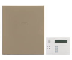
How Do I Perform Smoke Reset on a VISTA-20P Via a 4204?
Connect the 4204 to the panel's keypad bus. Choose an address (12 - 15) and set the dip switches. Program the 4204 in panel programming locations *79 and *80. Connect a wire from Power Positive (+) to Relay Common. Connect another wire from Relay Normally Closed (NC) to Smoke Positive (+).
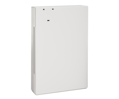
4204 Connection to Panel and Programming
The 4204 Relay Module connects to the VISTA-20P panel through the keypad bus. Any 4204 that you connect must have a unique address. On a VISTA-20P the 4204 can use addresses twelve through fifteen. The dip switch settings for the module address* are as follows:
4204 Addresses 00 - 15 - Dip Switch Settings:
| DEVICE ADDRESS | ||||||||||||||||
|---|---|---|---|---|---|---|---|---|---|---|---|---|---|---|---|---|
| DIP SWITCH NUMBER ↓ |
0 | 1 | 2 | 3 | 4 | 5 | 6 | 7 | 8 | 9 | 10 | 11 | 12 | 13 | 14 | 15 |
| 2 | ON | — | ON | — | ON | — | ON | — | ON | — | ON | — | ON | — | ON | — |
| 3 | ON | ON | — | — | ON | ON | — | — | ON | ON | — | — | ON | ON | — | — |
| 4 | ON | ON | ON | ON | — | — | — | — | ON | ON | ON | ON | — | — | — | — |
| 5 | ON | ON | ON | ON | ON | ON | ON | ON | — | — | — | — | — | — | — | — |
| 6 | ON | ON | ON | ON | ON | ON | ON | ON | ON | ON | ON | ON | ON | ON | ON | ON |
4204 Addresses 16 - 31 - Dip Switch Settings:
| DEVICE ADDRESS | ||||||||||||||||
|---|---|---|---|---|---|---|---|---|---|---|---|---|---|---|---|---|
| DIP SWITCH NUMBER ↓ |
16 | 17 | 18 | 19 | 20 | 21 | 22 | 23 | 24 | 25 | 26 | 27 | 28 | 29 | 30 | 31 |
| 2 | ON | — | ON | — | ON | — | ON | — | ON | — | ON | — | ON | — | ON | — |
| 3 | ON | ON | — | — | ON | ON | — | — | ON | ON | — | — | ON | ON | — | — |
| 4 | ON | ON | ON | ON | — | — | — | — | ON | ON | ON | ON | — | — | — | — |
| 5 | ON | ON | ON | ON | ON | ON | ON | ON | — | — | — | — | — | — | — | — |
| 6 | — | — | — | — | — | — | — | — | — | — | — | — | — | — | — | — |
*Older 4204 modules may have fewer dip switches. Dip switch 1 enables or disables the module's cover tamper. Dip switch 1 OFF = Tamper enabled. Dip switch 1 ON = Tamper disabled. Dip switch 7 currently has no function.
Connect the 4204 to the VISTA-20P keypad bus as shown below. Be sure to observe the wiring length limitations based on the gauge wire used. You can find these limitations in the VISTA-20P Install Guide on page 2-5. Since the smoke detectors you intend to reset will be wired back to the panel, installing the 4204 near the VISTA-20P control is recommended and should prevent any wiring length concerns.
| VISTA-20P | 4204 |
|---|---|
| Panel Terminal 4 (Black) | 4204 Terminal 15 |
| Panel Terminal 5 (Red) | 4204 Terminal 13 |
| Panel Terminal 6 (Green) | 4204 Terminal 14 |
| Panel Terminal 7 (Yellow) | 4204 Terminal 16 |
Once the 4204 has been connected to the panel's keypad bus and the dip switches have been set to a proper address (12 - 15), you'll need to enable the 4204 in panel programming. To do so, follow these steps:
-
Enter Programming. On an alpha keypad such as a Honeywell Home 6160, enter Installer Code (4112 by default) + [8] + [00] The keypad will display "Installer Code - 20". If you don't know the installer code, you can enter programming through the back door by powering the system down completely, and pressing the * and # keys simultaneously within 50 seconds of powering back up. It is possible to disable the back door option, so if you're working with a panel that you're not completely familiar with, know that pressing * and # together can cause a panic alarm. It could be a silent panic, in which case you could set off a panic alarm without knowing:

-
Enter Device Mapping (*79). At the keypad enter [*79]. You'll be prompted to enter an output number. Think of this as the name for the individual relay. On the VISTA-20P each relay on a 4204 uses one (1) output number. Up to four (4) relay modules can be added, which means output numbers 01 - 16 are potentially available. Each relay from a 4204 that will be used needs to be mapped to an Output Number. Assuming this is your first 4204 and you'll be using relay 01, entering 01 here is appropriate. If you already have one or more 4204s on the system, enter the next unused output number. Press [*] to advance to the next screen. The rest of the prompts for this output are as follows:
- Output Type = Enter 1. This tells the VISTA-20P you're working with a Relay. Press [*] to save and advance to the next prompt.
- 01 Module Address = Enter the address set using the 4204 dip switches. This will be digits 12 - 15 depending on the number of 4204 modules used. If you set the dip switches to address 12, enter 12 here. Press [*] to save and advance.
- 01 Relay Position = Enter the relay number designation within the 4204 that the smoke reset wiring is connected to. If you are wired to Relay 1, enter 01 here. Press [*] to save and advance.
- Exit Device Mapping. After the previous prompt you'll be back to the "Enter Output No." screen. To exit, enter 00. This brings you out of the *79 menu mode back to the VISTA-20Ps regular programming. We can now move on to *80 Output Programming. This is where we tell the panel how this relay will behave.
-
Enter Output Function Programming. From the VISTA-20P's regular programming screen, press *80. You'll be prompted for "Output Funct. No." The VISTA-20P supports up to 48 Output Functions. If this is the first relay you're programming, enter 01. Press [*] to advance. The remaining prompts for this output function number are shown below:
- Summary Screen. A screen showing a summary of any existing output function programming is displayed. If there has been no previous programming, the summary screen will show all 0's. Press [*] to move to the next prompt.
- 01 Activated By: The number displayed (01) is the output function currently being programmed. Enter 2 for Zone Type here. Press [*] to save and advance to the next prompt.
- 01 Enter Zn. Type. There are many potential options here, but for smoke reset enter 54 for "Fire Zone Reset". You'll be prompted to enter a partition number. You can enter 1 or 2 corresponding to the smoke detector's partition, or you can enter 0 for "Any Partition". Press [*] to save and advance.
- 01 Output Action: When Zone Type 54 is used to activate a relay, the action is automatically programmed. You should see "Close for 2 sec" with a 1 in the lower right corner of the screen. Press [*] to save and advance.
- Enter Output No. This refers back to the programming in *79, the name you gave the relay. Enter the output number you programmed with the 4204 address and relay number specified. If this is your first 4204 module and you plan to connect to Relay 1 on that module, then you will likely enter 01 here. Press [*] to save and advance.
- Summary Screen. You'll see another summary screen. This time filled with the programming you performed. The example below is based on our programming examples above. Press [*] to continue.
- Output Function No. This brings you back to the "Enter Output Function No." prompt. If you are finished with relay programming enter 00 to exit the *80 menu mode and return to regular programming. From here, you can exit VISTA-20P programming by pressing [*99].
Summary Screen Explanation:
The top row from left to right is:
01 - Output Function Number, A - Action, E - Event, P - Partition, and Trig - Trigger.
The bottom row from left to right is:
Output Number - R01, indicating this is a relay programmed via *79 as Output 01, Action 1 - Close for 2 Seconds, Event - Not Used with Zone Type, Partition - 0 (any), and Trigger - Zone Type 54 (fire zone reset).


Relay and Smoke Detector Wiring
This entire setup is required only for 4-wire smoke detectors. When using 2-wire smokes, they should only be connected to a zone specified for 2-wire smoke detectors. On the VISTA-20P, that's Zone 1. Check the smoke manufacturer's compatibility information to be sure you are using compatible smoke detectors. Zone 1 has internal programming that supervises smoke power and follows smoke reset logic automatically, without additional programming or wiring.
Once the 4204 Relay Module is addressed, connected to the panel's keypad bus, and programmed you're ready to connect the smoke power wiring. Connect the smoke's zone wiring to any hardwired zone except Zone 1. We recommend breaking the positive leg of smoke power when performing the reset. With that in mind:
- Connect Power Negative (–): Run a wire from the smoke detector’s negative power terminal to one of the following:
- Panel Terminal 4 (–)
- 4204 Relay Module Terminal 15
- The DC Negative (–) terminal of a separate power supply
- Connect Power Positive (+): Wire from the power source to the Normally Closed (NC) terminal of the 4204 Relay Module. In our example using Relay 1, Normally Closed is Terminal 2.
The positive voltage source can be one of the following:- Panel Auxiliary Power Positive (Panel Terminal 5)
- 4204 Terminal 13 (panel power passthrough)
- A separate power supply (see Important Note above for grounding requirements)
- Connect Relay Common (C): Wire from the C terminal of the relay to the positive (+) IN of the first smoke in the zone. In our example using Relay 1, this is Terminal 3. The smoke detectors in the example below are System Sensor 4W-B and 4WT-B detectors. They have a Positive (+) IN and Positive (+) OUT terminal to feed power to the next detector in the circuit, or to connect to the power supervision relay.

VISTA-20P Smoke Reset Logic Explained
Fire Zone reset logic works like this:
- Fire Alarm Occurs:
When a hardwired smoke detector goes into alarm, it creates a short on its assigned zone. This triggers the fire alarm system. - Disarm the System:
The user silences the alarm by entering a disarm command on the VISTA-20P keypad.
The alarm sound stops, but the short on the fire zone remains. This is intentional. When multiple smoke detectors are on the same zone, the LED on the activated detector remains lit so you can identify which detector triggered the alarm. - Perform the Reset:
When ready to reset the smoke detectors, the user performs a second disarm command on the keypad.
This triggers the panel’s Zone Type 54 – Fire Zone Reset logic:- The panel confirms that the zone (excluding Zone 1) still shows a short after the first disarm.
- The second disarm causes the assigned relay to activate for two seconds.
- This momentarily drops power to the smoke detectors, which clears their alarm state and releases the short.
End Of Line Power Supervision Relay
Because hardwired smoke detectors are Normally Open (NO) devices, regardless of whether they have power, it's of paramount importance to ensure they always receive consistent power. To accomplish this, an end-of-line power supervision relay, such as the EOLR-1 shown in the diagram above, must be installed.
The smoke detectors will still function properly without this relay, but only as long as they are receiving power. The problem is, without the power supervision relay the only indication that the smokes have lost power is the loss of LED status function. This is easily overlooked. If a fire occurs while any smokes are without power those smoke detectors will not function. This is a life-safety hazard. So, we recommend using a power supervision relay with any 4-wire smokes.
This relay is a Normally Closed (NC) device and should be powered by the same source as the smoke detectors. It must be installed after the last smoke detector in the loop, to ensure its ability to supervise the entire smoke detector power circuit. Refer to the relay’s installation guide for correct end-of-line resistor (EOLR) placement.
This setup forms a parallel/series hybrid circuit:
- If a smoke detector activates, the zone detects a short and triggers a fire alarm.
- If power is lost, the supervision relay opens, preventing the panel from seeing the EOL resistor.
- The panel interprets this as a trouble condition, alerting you to a power failure on the smoke detector loop.
Did you find this answer useful?
We offer alarm monitoring as low as $10 / month
Click Here to Learn MoreRelated Products


- Answered
- Answered By
- Julia Ross