How Do I Perform Tests on The Qolsys IQ Panel 4 Panel?
Perform system tests on the Qolsys IQ Panel 4 by touching the grey tab at the top of the home screen. Then select settings > advanced settings > enter Master/Installer/Dealer Code (default 1234/1111/2222) > System Tests. Here you can run tests for communications, sensors, hardware, and more.

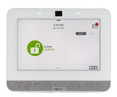
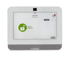
The Qolsys IQ Panel 4 is a sleek panel that features a 7" capacitive multi-touch touchscreen and supports 128 zones, and 242 users. It is available in black or white and comes with a built-in 700-Series Z-Wave Plus V2 controller, Bluetooth, Dual-Band WIFI, PowerG, and LTE Cellular modules. You may opt for either a Verizon or AT&T version. In addition to the panel color and the cellular carrier, users can choose from one of three (3) Legacy RF compatible versions. There is a 345 MHz Honeywell or 2GIG compatible, 319.5 MHz Qolsys or Interlogix GE compatible, or 433 MHz legacy DSC compatible model. There is also a PowerG-only IQ Panel 4 version that does not offer legacy receiver support. Every IQ Panel 4 uses Alarm.com interactive remote services.
System Tests
To access the system tests on an IQ Panel 4, touch the grey tab at the top of the home screen. Then select settings > advanced settings > enter Master/Installer/Dealer Code (default 1234/1111/2222 respectively) > System Tests. From here you will see the various tests listed in the screenshot below. Click on each section to get more in-depth details for each.
Please Note:
- The 'Daughter Cards Test' does not show up when using the Master code to access this menu.
- 'Zigbee Test' is not pictured below. A Zigbee card must be installed before this test will be offered.
- Ambient Noise Test is only available after it has been enabled in Installer or Dealer settings. This option can only be enabled if the panel glass break detector is disabled, and vice-versa.
- WIFI
- Sensor
- Cellular
- Z-Wave
- PowerG
- Zigbee
- Panel Glass Break
- Dual Path WIFI
- Daughter Cards
- Panel
- Ambient Noise
- Input Voltage

Table of Contents:
WIFI
Wi-Fi Test checks the connection of the IQ4 to the WIFI network only. (Dual Path WIFI verifies a link all the way to Alarm.com) To access the system tests on an IQ Panel 4, touch the grey tab at the top of the home screen. Then select settings > advanced settings > enter Master/Installer/Dealer Code (default 1234/1111/2222) > System Tests. Next, follow the steps below.
1. Select Wi-Fi Test. From the test menu, select Wi-Fi Test.
2. Select Run. Click Run and the results will be displayed on the screen. A Pass indicates a successful result. Displayed will also be the time at which the test was run and the connection speed. If you get a failed result, please check your WIFI settings.
3. Exit. If you would like to return to the System Test menu, hit the back button at the bottom left. If you are finished with all desired tests, press the Home button at the bottom of the screen.

Sensor
The sensor test provides the signal strength of the sensor and also graphs the sensor events against the ambient RF noise floor of the environment. This section will only allow you to test the legacy RF sensors. PowerG sensors are tested under 'PowerG test'. To access the system tests on an IQ Panel 4, touch the grey tab at the top of the home screen. Then select settings > advanced settings > enter Master/Installer/Dealer Code (default 1234/1111/2222) > System Tests. Next, follow the steps below.
1. Select Sensor Test. Select the Sensor Test option from the list of available System Tests. Choosing this option will begin testing the sensors. On the initial test, the panel will obtain all of the sensor RF data. Then it will display all sensors in a list.
2. Activate sensors. You must activate each sensor to get the details to load. Once activated, the system will populate the average and the latest signal strength in decibels. It will also show a packet rating indicating how many packets were received. The IQ4 will also provide a graph option to see the signal in graph form.

The graph below shows a sensor level indicated by the green dots. The yellow line below it represents a poor signal level. The poor signal level is 12 dBm above the ambient noise floor in the environment. If the sensor level dips into the poor range, then RF failures can occur. The red line represents a critically poor signal level. This line is 6 dBm above the noise floor. Sensor levels that dip into this area are very likely to have RF failures. If the sensor level being displayed is in yellow or red, try moving it to a different part of the door or window, or changing its orientation. Then run the test again.

3. Exit. If you would like to return to the System Test menu, hit the back button at the bottom left. If you are finished with all desired tests, hit the Home button at the bottom of the screen.
Cellular
The Cellular test checks the panel's connection to the cellular network and Alarm.com. The panel needs to be activated and monitored before running this test. To access the system tests on an IQ Panel 4, touch the grey tab at the top of the home screen. Then select settings > advanced settings > enter Master/Installer/Dealer Code (default 1234/1111/2222) > System Tests. Next, follow the steps below.
1. Select Cellular Test. From the test menu, select the Cellular Test option. This allows you to test the built-in cellular radio connection.
2. Select start. The panel will begin to run the test. This will also populate a cell signal strength after the test has been completed.

3. Exit. If you would like to return to the System Test menu, hit the back button at the bottom left. If you are finished with all desired tests, hit the Home button at the bottom of the screen.
Z-Wave
This test will verify communication between enrolled devices and the panel. This section also provides diagnostic tools such as rediscover network, counters, neighbor info, diagnostics, and advanced diagnostics. To access the system tests on an IQ Panel 4, touch the grey tab at the top of the home screen. Then select settings > advanced settings > enter Master/Installer/Dealer Code (default 1234/1111/2222) > System Tests. Next, follow the steps below.
1. Select Z-Wave Tests. When on the main system test screen, select Z-Wave Tests. This will take you into the Z-Wave Tests menu.
2. Select Z-Wave Test. Here you will find many tools for optimizing and managing your Z-Wave network. These include Z-Wave Test, Rediscover Network, Neighbor Info, Counters, Z-Wave Diagnostics, and Advanced Z-Wave diagnostics. Select Z-Wave test to test enrolled Z-Wave devices. Below we explain all the other tests.

Z-Wave Test - This test will check the connection between the panel and the enrolled Z-Wave device(s). Options include "Run". This test is used when you may suspect an issue with a device, or want to ensure a particular device is properly communicating.
Rediscover Network - This re-maps all devices in the network, making sure they all have the best route back to the panel. Options include "Rediscover". Use this test after you have added any new devices or removed any devices.
Neighbor Info - This will show all devices that can be seen by the selected Z-Wave device. The more devices it can see, the more possible routes back to the controller and the stronger the network. Options include "View". Use this for informational purposes, to view neighboring devices.
Counters - Provides a numerical representation of the Z-Wave network. Allows you to see failed and acknowledged commands. A strong network should maintain at least a 98% acknowledged vs failed rate. Options include "Reset All" and "Details". Reset all will reset all counters. Details will show acknowledged and failed commands listed per device and provide an option to reset counters per device. Use this to check how well each device is communicating.
Counter Terminology
Explains what each of the counters mean
| Counter | Description |
|---|---|
| Acked commands no auto route | Command was successful and acknowledged but it did not use the normal network route. The command was re-routed in order to succeed. |
| Acked commands auto route | Command was successful and acknowledged. It used the normal network route. |
| Failed commands no ack |
Not possible to transmit data because the network was busy or jammed. Command failed to execute. |
| Failed commands network failed | Not possible to transmit data because the network was busy or jammed. Command failed to execute. |
| Failed commands network not idle | Auto-routed command failed because the network was not yet stable. Command failed to execute. |
| Failed commands network no route | Auto-routed command failed because there is no network route to the device. Command failed to execute. |
| Reset All | Resets all counters back to zero (0) to better diagnose the network. |
| Details | Shows individual device details as passed or failed commands. Here you can also reset an individual device's counter. |
Z-Wave Diagnostics - This will provide a layout of the Z-Wave network. See the last known working route of the entire network with individual devices mapped out. Also, see the signal strength of each device. Use this to get a graphical representation of the network.
Advanced Z-Wave Diagnostics - Provides access to Network Health, Repeater, and Last working route tests.
Network Health Test - This shows transmission count, packet error count, route changes, neighbors, and transmission times of the enrolled devices. Options include "Run". Use this to see the health of the network.
Repeater Test - Tests the connection to dedicated Z-Wave repeaters. This does not include AC powered Z-Wave devices that act as repeaters, but devices that are only Z-Wave repeaters. Use this to see how well the network repeaters are working.
Last Working Route - This will show the last working route for a specific node on the network. Also, it allows you to set a static "sticky" route. This allows you to specify a specific route for each device. Options include "View" and "Edit". View will show what node the device is working through or if it's a direct route to the panel. 'Edit' will allow you to specify which node you want the device to work through. Use this with caution, as most installs work best when the controller selects the route. The 'Rediscover Network' option mentioned above, will allow the panel to re-specify the route and clear this "sticky" route. Use this to see what node(s) each device is working through.
3. Select the Run button. To initiate the Z-Wave test, touch the Run button for each desired device. When completed successfully, it will populate a time stamp and indicate "Pass" under the result column. If the device fails, check device power, relocate the device, and/or rediscover the Z-Wave network.

4. Exit. If you would like to return to the System Test menu, hit the back button at the bottom left. If you have completed all desired tests, hit the Home button at the bottom of the screen.
PowerG
The PowerG test checks the signal by pinging and receiving signal strength from PowerG sensors. To access the system tests on an IQ Panel 4, touch the grey tab at the top of the home screen. Then select settings > advanced settings > enter Master/Installer/Dealer Code (default 1234/1111/2222) > System Tests. Next, follow the steps below.
1. Select PowerG Test. From the System Test screen, select PowerG Test. You will then see the serial number, zone name, and strength. Strength can be strong, good, poor, or no signal.

2. Click Run. Click run to begin testing each sensor. Selecting 'More' will provide additional sensor signal info, including 24 hour strength and firmware version of the sensor. You will also find a 'Run' button, to start the test. For motions there is a Test LED button that will verify the LED is functioning properly, by causing it to blink for two (2) minutes. For PowerG Image sensors, there will also be a Test Picture button.
3. Exit. If you would like to return to the System Test menu, hit the back button at the bottom left. If you are finished with all desired tests, hit the Home button at the bottom of the screen.
Zigbee
When you have a Zigbee daughter card installed, this test will populate on the System Test menu. This test shows the most recent signal strength, average signal strength, and battery voltage for Zigbee sensors. To access the system tests on an IQ Panel 4, touch the grey tab at the top of the home screen. Then select settings > advanced settings > enter Master/Installer/Dealer Code (default 1234/1111/2222) > System Tests. Next, follow the steps below.
1. Select Zigbee Test. From the System Tests screen, select the Zigbee Test option. This will provide the recent signal strength, average signal strength, and battery voltage of the Zigbee Sensors. The signal strength is indicated by strong, good, poor, or no signal.
2. Exit. If you would like to return to the System Test menu, hit the back button at the bottom left. If you are finished with all desired tests, hit the Home button at the bottom of the screen.
Panel Glass Break
Test the panel's microphones for proper sensitivity for the built-in glass break. For proper glass break detection, the panel must be wall mounted, not desk mounted. It must also be connected to the power supply. It can detect different types of framed glass breakage, including tempered, plated, and insulated with a minimum dimension of 12" X 12" (30.5mm x 30.5mm). The IQ4 will detect glass breaking from 3' - 15' away from the wall-mounted panel with no obstacles between the panel and the protected glass. To access the system tests on an IQ Panel 4, touch the grey tab at the top of the home screen. Then select settings > advanced settings > enter Master/Installer/Dealer Code (default 1234/1111/2222) > System Tests. Next, follow the steps below.
1. Select Panel Glass Break Test. To access from the System Tests screen, select Panel Glass Break Test.
2. Select the desired test. It has 3 options, which include a Clap Test, a Glass Break Simulator Test, and a Glass Break Alarm Test mode. Use the Reset button to end either test.

- To run the Clap Test, select Run. This will start the test and activate the microphones. A successful clap test will provide a yellow circle. The circle will turn green when the panel hears the glass break frequency.
- To run the Glass Break Simulator Test, select Start. This enables a 15 minute test mode that will allow the panel to recognize a glass break simulator, like a Honeywell FG701, you can also play a glass break sound such as this one. The circle will turn green when the panel hears the glass break frequency.
- To run the Glass Break Alarm Test Mode be sure to put your account on test with the monitoring station. Next, select Start. This will also enable a 15 minute test mode that will allow the panel to recognize a glass break simulator. Next you must Arm Away, then activate the glass break simulator and the panel will go into alarm and send a signal to the monitoring station. The panel will auto exit this test mode in 15 minutes.

3. Exit. If you would like to return to the System Test menu, hit the back button at the bottom left. If you have completed all desired tests, hit the Home button at the bottom of the screen.
Dual Path WIFI
This is different than the WIFI test, as this test verifies the WIFI is connecting all the way back to Alarm.com. The panel must be connected to a WIFI network to enable Dual-Path. To access the system tests on an IQ Panel 4, touch the grey tab at the top of the home screen. Then select settings > advanced settings > enter Master/Installer/Dealer Code (default 1234/1111/2222) > System Tests. Next, follow the steps below.
1. Select Dual Path WI-FI Test. Select Dual Path Test to begin. Here you will find an option to uncheck (on by default) Dual-Path Control. This will cause the panel to use cellular only and will not allow this test to be run.
2. Select Start. With Dual-Path Control enabled, select the Start option. This tests the WIFI connection to Alarm.com.
3. Exit. If you would like to return to the System Test menu, hit the back button at the bottom left. If you are finished with all desired tests, hit the Home button at the bottom of the screen.

Daughter Cards
This test is only available when using the Installer or Dealer code (defaults 1111/2222). This menu will test the integrity of the installed daughter cards. These include the legacy RF receiver card, the PowerG card, and the Zigbee card, if installed. Note that the IQ4 supports a maximum of two (2) radio cards in the available slots. The Z-Wave can also be tested here but it is integrated and not part of the two (2) radio card limit. To access the system tests on an IQ Panel 4, touch the grey tab at the top of the home screen. Then select settings > advanced settings > enter Installer/Dealer Code (default 1111/2222) > System Tests. Next, follow the steps below.
1. Select Daughter Cards Test. Select Daughter Card Test to access the option to run a test to check the integrity of each individual daughter card.
2. Select Run. For the desired card, select Run. In some cases it may take several minutes for the test to complete. You will get either a "Pass" or "Fail" when the test has been completed. A failed result requires checking the daughter card connection, then rebooting the panel and testing again.
3. Exit. If you would like to return to the System Test menu, hit the back button at the bottom left. If you are finished with all desired tests, hit the Home button at the bottom of the screen.

Panel
This will test the panel's running processes. You have the option to run all at once or select the desired option. Options include Arm-Disarm, Camera, Photos, Help Videos, Battery, LED Blue/Red/Green, Panel Tamper, AC status, Internet Connection, WIFI, Upgrade Service, Z-Wave, and Sirens. You can also select "Clear All" to erase any previous results. To access the system tests on an IQ Panel 4, touch the grey tab at the top of the home screen. Then select settings > advanced settings > enter Master/Installer/Dealer Code (default 1234/1111/2222) > System Tests. Next, follow the steps below.
1. Select Panel Test. From the System Tests screen, select Panel Test. You will have a list of all available panel processes to test. You can scroll to a specific test, run all at once, or select Clear All to erase previous results on all tests.
2. Run or Run All. To begin the test, scroll down to the desired test and select Run. To run all the tests, press "Run All". Please note that running all tests includes the siren test, so be prepared to hear the siren sound.
3. Exit. If you would like to return to the System Test menu, hit the back button at the bottom left. If you have completed all desired tests, hit the Home button at the bottom of the screen.

Ambient Noise
This test is only available when enabled in the Installer/Dealer settings (touch the grey tab at the top of the home screen > settings > advanced settings > enter Installer/Dealer Code (default 1111/2222) > Installation > Installer/Dealer Settings). Panel Glass Break Detector must be disabled to enable the Panel Ambient Noise Detector. After being enabled, it will use the panel's built-in microphones to monitor for loud noise above a selected decibel rating. It provides feedback detailing the min/max db, average db, current db, and the number of times the threshold was reached. In Installer/Dealer settings, the threshold is a selectable value from 75db-95db. To access the system tests on an IQ Panel 4, touch the grey tab at the top of the home screen. Then select settings > advanced settings > enter Master/Installer/Dealer Code (default 1234/1111/2222) > System Tests. Next, follow the steps below.
1. Select Ambient Noise Test. From System Tests select the Ambient Noise Test. This allows access to the test. The test checks the noise level around the panel.
2. Select Start. To begin the test, select Start. The circle to the right has 3 options. A green circle labeled Safe Volume, a yellow circle labeled Approaching Threshold, and a red circle labeled Threshold Breached. The IQ4 will also provide the statistics at the bottom of the screen. It provides the minimum, maximum, average, and current decibel levels. It will also show the number of times the threshold was breached.
3. Select Stop. If you need to pause or quit the test, hit the stop button. This will provide two button options. A Resume and a Reset button. Resume will allow the test to continue and reset will change all the statistics back to zero (0).
4. Exit. If you would like to return to the System Test menu, hit the back button at the bottom left. If you have completed all desired tests, hit the Home button at the bottom of the screen.

Input Voltage
This test measures the DC voltage the panel is currently receiving. It will also provide a status of 6VDC and above being good. Below 6VDC, will provide a low voltage message. This will require looking into causes of low voltage. This can include running the power wire too long or using too small of a wire gauge for power. To access the system tests on an IQ Panel 4, touch the grey tab at the top of the home screen. Then select settings > advanced settings > enter Master/Installer/Dealer Code (default 1234/1111/2222) > System Tests. Next, follow the steps below.
1. Select Input Voltage Test. To check the voltage level of the panel, select the Input Voltage Test. The IQ4 will measure the voltage received in real-time.
2. Select Start. To begin the test, select the Start button. In return, you will receive a "Voltage is Good" or a "Voltage is Low" message. The results can vary each time you run the test based on the current draw of the panel at that time. Low voltage is the result of a test result lower than 6VDC. This is usually caused by a bad wire or a custom wire exceeding the recommended limitations. The recommended wire length is 98.5ft (30m) using 18AWG wire. The wire gauge, at a minimum, should be at least 22AWG. Be sure that the panel is not plugged into a switched outlet with the switch turned off.
3. Exit. If you would like to return to the System Test menu, hit the back button at the bottom left. If you are finished with all desired tests, hit the Home button at the bottom of the screen.

Did you find this answer useful?
We offer alarm monitoring as low as $10 / month
Click Here to Learn MoreRelated Products


Related Videos

- Answered
- Answered By
- Freddie Daniels